EP1452732A1 - Auftriebsmotor - Google Patents
Auftriebsmotor Download PDFInfo
- Publication number
- EP1452732A1 EP1452732A1 EP03004535A EP03004535A EP1452732A1 EP 1452732 A1 EP1452732 A1 EP 1452732A1 EP 03004535 A EP03004535 A EP 03004535A EP 03004535 A EP03004535 A EP 03004535A EP 1452732 A1 EP1452732 A1 EP 1452732A1
- Authority
- EP
- European Patent Office
- Prior art keywords
- float
- air
- transmission
- gear
- hydraulic
- Prior art date
- Legal status (The legal status is an assumption and is not a legal conclusion. Google has not performed a legal analysis and makes no representation as to the accuracy of the status listed.)
- Withdrawn
Links
- 230000005540 biological transmission Effects 0.000 claims abstract description 44
- XLYOFNOQVPJJNP-UHFFFAOYSA-N water Substances O XLYOFNOQVPJJNP-UHFFFAOYSA-N 0.000 claims abstract description 34
- 230000033001 locomotion Effects 0.000 claims description 4
- 238000013459 approach Methods 0.000 claims description 3
- 238000007599 discharging Methods 0.000 claims description 2
- 230000000694 effects Effects 0.000 claims description 2
- 238000004519 manufacturing process Methods 0.000 description 4
- 238000010248 power generation Methods 0.000 description 4
- 230000000903 blocking effect Effects 0.000 description 3
- 239000000463 material Substances 0.000 description 2
- 238000003825 pressing Methods 0.000 description 2
- 238000003466 welding Methods 0.000 description 2
- 206010038743 Restlessness Diseases 0.000 description 1
- 208000003443 Unconsciousness Diseases 0.000 description 1
- 238000011161 development Methods 0.000 description 1
- 238000005562 fading Methods 0.000 description 1
- 230000009916 joint effect Effects 0.000 description 1
- 238000012423 maintenance Methods 0.000 description 1
- 238000000034 method Methods 0.000 description 1
- 238000011160 research Methods 0.000 description 1
Images


Classifications
-
- F—MECHANICAL ENGINEERING; LIGHTING; HEATING; WEAPONS; BLASTING
- F03—MACHINES OR ENGINES FOR LIQUIDS; WIND, SPRING, OR WEIGHT MOTORS; PRODUCING MECHANICAL POWER OR A REACTIVE PROPULSIVE THRUST, NOT OTHERWISE PROVIDED FOR
- F03B—MACHINES OR ENGINES FOR LIQUIDS
- F03B17/00—Other machines or engines
- F03B17/02—Other machines or engines using hydrostatic thrust
- F03B17/04—Alleged perpetua mobilia
Definitions
- the present invention relates to hydraulic buoyant force engine, in particular, to a machine which is capable of operating to generate power exclusively driven by buoyancy.
- the conventional power generation can usually be classified into two categories, e,g. power generation by means of force of nature, such as hydraulic power and wind power, the other one is power generation consuming natural resources, such as neuclear power and steam power.
- the hydraulic buoyant force engine of the present invention comprises a plurality of canvas enclosed floats each provided with an air inlet and an air outlet float up and sink down in a water tank along a central transmission bar by expanding and shrinking alternatively in accordance with the action absorbing the air into the float and releasing the air out of the float by means of an air guide unit connected to the float and emerged out of the water surface.
- the pureical power produced by motion of the floats is transmitted to an output shaft trough two sprocket and chain units each provided at one side of the floats so as to produce a continuous and restless mechanical power.
- the expansion and shrinkage of the float are performed by joint action of precisely designed gear mechanism and pivoted lever together with its actuation rod.
- the water tank may be configurated in a L shaped polyhedron, or a regular polyhedron.
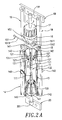
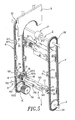
- a float 1 the essential component of the present invention, and its expansion and shrinking states are illustrated.
- the component structure of the float 1 includes:
- a tunnel like through hole 153 is opened in the base at a properly offset position beneath the pivoted axle 152, at the end of the through hole 153 near the pivot axle 152, a clogging portion 1531 is formed, while the other end is formed into a threaded portion 1532. Further, a ball 154 is placed in the clogging portion 1531, and a coil spring 155 is set in the through hole 153 with its one end forcibly pressing the ball 154, while the other end thereof is engaged with the threaded portion 152 by screw combination. As shown in figs.
- a bevel gear 16 encircles one end of the transmission bar 11 at the stationary base (15) side, and a gear wheel 17 is provided on it.
- a first joint plate 19 formed above the gear wheel 17 is provided with an end support 191 at its inner side center portion thereof, and two tapped holes are formed on the joint plate 19 each at one side of the end support 191 for engaging with the two stands 18.
- a second joint plate 20 formed under the float 20 also has an end support 201 at is center portion, and are provided with two tapped holes each at one side of the end support 201 to be engaged with staples of a transmission chain (to be described later on).
- the two end supports 191, 201 are for supporting the transmission bar 11.
- both bearing blocks 12 are moved relatively close to each other such that the three ribs 131, 132, 133 are retracted inwards thereby the canvas 14 is shrunk (see Fig. 2A).
- both bearing blocks 12 are moved away form each other such the three ribs 131, 132, 133 stretch outwards thereby causing the canvas 14 expanded (see Fig. 2B).
- the float 1 floats up or sinks down in the water.
- the transmission mechanism includes:
- Fig. 5 is a perspective view showing the internal structure of the present invention.
- the first joint plate 19 is engaged with the staple 61 of the first transmission chain 6 by screw combining its tapped hole with the tapped hole 611 of the staple 61, or by welding thereof such that the first joint plate 19 at one end of the float 1 is firmly engaged with the first transmission chain 6; similarly the second joint plate 20 is engaged with the staple 71 of the second transmission chain 7 by screw combining its tapped hole with the tapped hole 711 of the staple 71, or by welding thereof such that the second joint plate 20 at the opposite end of the float 1 is firmly engaged with the second transmission chain 7.
- the float 1 is settled between the two chains 6 an 7 so as to move together with them at a track defined by the two chains 6 and 7.
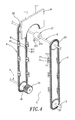
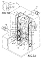
- Fig. 6 is the side view of Fig. 5, and further refer to Figs. 7A and 7B, several floats 1 can be connected between the first and the second chains 6, 7, in order to make all the floats 1 be communicated with each other, a four-way tube 101 can be provided to an air inlet/outlet 143 installed at the outer side of one of the floats 1, and a three-way tube 102 can be provide at the inner side thereof, and the three-way tubes 102 are provide to both inner/outer air inlet/outlet 143 for rest of the floats 1. Furthermore, a hose 103 is used to interconnect each air inlet/outlet 143 of the floats 1.
- FIG. 7A An embodiment of the present invention is illustrated in Fig. 7A.
- a L shaped water tank 9 constructed according to Torricelli's law is provided, a first electromagnetic valve 91 is installed at the right upper side of the water thank 9, while a second electromagnetic valve 92 is installed at the left lower side thereof. Water is supplied into the water tank 9 from the second electromagnetic valve 92. At this moment the first electromagnetic valve 91 is at closed state so that water can not overflow therefrom. The state of closing the valve 91 and opening the valve 92 is maintained until the water level reaches a height below the output shaft 2. Then the valve 92 is closed, and the valve 91 is opened. At this state, water does not flow out from the valve 92 according to Torricelli's law, and the pressure inside the water tank 9 is reduced so that the floats can move along smoothly.
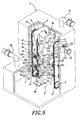
- the output shaft 2 and transmission shafts 3, 4 are fixed in the water tank 9, and a transmission gear wheel 24 is coupled to the output shaft 2 at one end extended out of the water tank 9 so as to output power.
- a ball bearing block 911 and an annular rubber collar 912 is applied to the tank wall at inner and outer side respectively from where the output shaft 2 goes out so as to prevent air leakage.
- the other end of the output shaft 2 and the fixed ends of both transmission shafts 3, 4 are all set at the wall surface of the water tank 4, and the annular rubber collar 912 is made of a friction resist and heat withstanding material.
- a miniature water tank 93 is equipped abut on the outer wall of the water tank 9 and is similarly pierced through by the output shaft 2.
- the wall of the water tank 9 where the output shaft 2 pierced through is provided with the ball bearing 911 and the annular rubber collar 912, whereas for the miniature tank 93, only an annular rubber collar 913 is provided.
- the first and the second transmission chains 6, 7 are set in the tank 9 and the air guide unit 21 on the output shaft 2 is emerged above the water level so as to let the air in.
- a first actuating rod 94 is provided at the rear upper inner wall of the tank 9, and a second actuating rod 95 is provided on the bottom of the tank 9 nearby the first chain 6.
- the two actuating rods 94, 95 are essentially for actuating the lever of the pivoted block 151 so as to cause the float 1 shrink or expand.
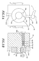
- the lever of the pivoted block 151 is apart from the surface of the bevel gear 16, before the float 1 approaches the driving gear wheel 41 of the transmission shaft 4 the second actuating rod 95 will tap the lever 151 in advance such that the lever 151 swings to the left and is blocked on the surface of the bevel gear 16.
- the pinion 17 is in mesh with the driving gear 42 and rotates. Meanwhile, by reason that the pivoted block 151 has an inlaid tension spring provided at its blocking terminal 1512 of the blocking rod 1511 (see Fig.
- the blocking terminal 1512 can not strongly trammel the bevel gear 16, but can only pressing it lightly.
- the two bearing blocks 12 of the float 1 is displaced gradually outward and extended so as to introduce external air into the float 1 via the air guide unit 21 thereby the float 1 is expanded.
- the first and the second chains 6, 7 are driven to move along and drive the other floats conjoined with the first and the second transmission chains 6, 7, and the output shaft 2 together with the transmission shaft 3, 4.
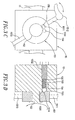
- the first actuating rod 94 taps the lever of the pivoted block 151 in advance so that the lever swings to the left and leaves away from the surface of the bevel gear 16 and the gear wheel 17 comes to, in mesh with the annular gear 8 and rotates. Then, the two bearing blocks 12 of the float 1 are gradually displaced inwards and the float 1 is shrunk to discharge the contained air into the other float which is gradually expanding.
- the float 1 which entirely lost its air sinks down in the water by its own weight and by driving force of the first and the second chains 6, 7. Each float repeats expansion and shrinkage restlessly so as to cause the first and the second chains 6, 7 also continuously to drive the output shaft 2 thereby a continuous mechanical power output can be obtained.
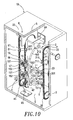
- the water tank 10 may be constructed poly hedrical as shown in Fig. 10.
- annular flange 213 is provided between the air outlet 211 and air inlet 212, and a check damper 214 is rockingly hinged abut on the annular flange 213 with a pivot axle 215.
- the required air may be absorbed from the air inlet 212 whereas the check damper 214 works to prohibit counter flow of air in the float.
Landscapes
- Engineering & Computer Science (AREA)
- Chemical & Material Sciences (AREA)
- Combustion & Propulsion (AREA)
- Mechanical Engineering (AREA)
- General Engineering & Computer Science (AREA)
- Other Liquid Machine Or Engine Such As Wave Power Use (AREA)
Priority Applications (1)
| Application Number | Priority Date | Filing Date | Title |
|---|---|---|---|
| EP03004535A EP1452732A1 (de) | 2003-02-28 | 2003-02-28 | Auftriebsmotor |
Applications Claiming Priority (1)
| Application Number | Priority Date | Filing Date | Title |
|---|---|---|---|
| EP03004535A EP1452732A1 (de) | 2003-02-28 | 2003-02-28 | Auftriebsmotor |
Publications (1)
| Publication Number | Publication Date |
|---|---|
| EP1452732A1 true EP1452732A1 (de) | 2004-09-01 |
Family
ID=32748833
Family Applications (1)
| Application Number | Title | Priority Date | Filing Date |
|---|---|---|---|
| EP03004535A Withdrawn EP1452732A1 (de) | 2003-02-28 | 2003-02-28 | Auftriebsmotor |
Country Status (1)
| Country | Link |
|---|---|
| EP (1) | EP1452732A1 (de) |
Cited By (6)
| Publication number | Priority date | Publication date | Assignee | Title |
|---|---|---|---|---|
| WO2006122558A1 (en) * | 2005-05-17 | 2006-11-23 | Lindhagen Joergen | A gravity driven water pxmp with a water energy producing module |
| GB2430471A (en) * | 2005-09-26 | 2007-03-28 | Blaise Coonan | Variable volume buoyancy engine |
| WO2007076719A1 (fr) * | 2005-12-31 | 2007-07-12 | Solar City Limited | Dispositif de production de puissance et dispositif de génération faisant intervenir celui-ci |
| GR1007323B (el) * | 2010-03-29 | 2011-06-22 | Γεμιστος, Παντελης Μιχαηλ | Υποβρυχιο συστημα παραγωγης ηλεκτρικης ενεργειας με υποβρυχιες πτυσσομενες δεξαμενες |
| WO2011091493A1 (pt) * | 2010-01-28 | 2011-08-04 | Cavalheiro Mario Teixeira | Máquina hidráulica de força em movimento circular na geração de energia elétrica em dois pontos de geração diferentes e máquina mecânica de força em movimento circular na geração de energia elétrica |
| EP2235362A4 (de) * | 2007-12-19 | 2013-07-10 | James Kwok | Hydrodynamisches energieerzeugungssystem |
Citations (3)
| Publication number | Priority date | Publication date | Assignee | Title |
|---|---|---|---|---|
| FR2260001A1 (en) * | 1974-01-31 | 1975-08-29 | Gomila Charles | Motor driven by hydrostatic thrust - has driving chambers with cyclically varying volumes |
| EP0452601A1 (de) * | 1990-04-20 | 1991-10-23 | Alexandre Fabry | Auftriebsmotor |
| GB2326916A (en) * | 1997-07-01 | 1999-01-06 | Ghem Sheng Whan | Buoyancy motor |
-
2003
- 2003-02-28 EP EP03004535A patent/EP1452732A1/de not_active Withdrawn
Patent Citations (3)
| Publication number | Priority date | Publication date | Assignee | Title |
|---|---|---|---|---|
| FR2260001A1 (en) * | 1974-01-31 | 1975-08-29 | Gomila Charles | Motor driven by hydrostatic thrust - has driving chambers with cyclically varying volumes |
| EP0452601A1 (de) * | 1990-04-20 | 1991-10-23 | Alexandre Fabry | Auftriebsmotor |
| GB2326916A (en) * | 1997-07-01 | 1999-01-06 | Ghem Sheng Whan | Buoyancy motor |
Non-Patent Citations (1)
| Title |
|---|
| ORD-HUME A W J G: "PERPETUAL MOTION", PERPETUAL MOTION. HISTORY OF AN OBSESSION, NEW YORK, ST. MARTIN'S PRESS, US, PAGE(S) 100-103, XP002067445 * |
Cited By (6)
| Publication number | Priority date | Publication date | Assignee | Title |
|---|---|---|---|---|
| WO2006122558A1 (en) * | 2005-05-17 | 2006-11-23 | Lindhagen Joergen | A gravity driven water pxmp with a water energy producing module |
| GB2430471A (en) * | 2005-09-26 | 2007-03-28 | Blaise Coonan | Variable volume buoyancy engine |
| WO2007076719A1 (fr) * | 2005-12-31 | 2007-07-12 | Solar City Limited | Dispositif de production de puissance et dispositif de génération faisant intervenir celui-ci |
| EP2235362A4 (de) * | 2007-12-19 | 2013-07-10 | James Kwok | Hydrodynamisches energieerzeugungssystem |
| WO2011091493A1 (pt) * | 2010-01-28 | 2011-08-04 | Cavalheiro Mario Teixeira | Máquina hidráulica de força em movimento circular na geração de energia elétrica em dois pontos de geração diferentes e máquina mecânica de força em movimento circular na geração de energia elétrica |
| GR1007323B (el) * | 2010-03-29 | 2011-06-22 | Γεμιστος, Παντελης Μιχαηλ | Υποβρυχιο συστημα παραγωγης ηλεκτρικης ενεργειας με υποβρυχιες πτυσσομενες δεξαμενες |
Similar Documents
| Publication | Publication Date | Title |
|---|---|---|
| US11591999B2 (en) | System for conversion of wave energy into electrical energy | |
| CA2696502C (en) | System and method for conversion of wave energy into electrical energy | |
| JP2008522084A (ja) | 波動エネルギー装置 | |
| US20080264056A1 (en) | Hydraulic buoyancey kinetic energy apparatus | |
| US20080092535A1 (en) | Systems and methods using gravity and buoyancy for producing energy | |
| EP1452732A1 (de) | Auftriebsmotor | |
| CN101391648B (zh) | 单自由度可调振幅平台 | |
| JP7019716B2 (ja) | 波動動力装置 | |
| CN103899492B (zh) | 一种浮海式风力水力发电装置 | |
| WO2008074214A1 (en) | Wind power generation device | |
| JP2010540835A (ja) | 流体を用いた動力発生装置 | |
| EP3622171B1 (de) | Brandungskraftwerk und verfahren zur stromerzeugung | |
| US20040093863A1 (en) | Hydraulic buoyant force engine | |
| DE19832232A1 (de) | Sonnenstrahlen - Umwandlung mit labil stehender, verankerter und abgestützter der Sonne nachlaufender Y-Achse sowie ausgewuchteter X-Achse | |
| JP2003139037A (ja) | 波力ポンプ | |
| JP6397513B2 (ja) | 浮力駆動の運動エネルギー発生装置およびその運動エネルギー発生方法 | |
| CN201277141Y (zh) | 海洋潮波收集发电机 | |
| KR20090056292A (ko) | 일측 상향 접철식 도어 구조체 | |
| US20010024038A1 (en) | Pendulum pump | |
| CN102678439A (zh) | 永久产生性动力装置 | |
| JP2004270502A (ja) | 浮力利用動的パワーマシン | |
| CN201420411Y (zh) | 立柱式自动停车棚 | |
| JP2018526582A (ja) | ダムレス水力発電装置 | |
| DE202015104787U1 (de) | Stromerzeugungsgerät | |
| FR3121185A1 (fr) | Système de production de l’électricité à partir des vagues de la mer |
Legal Events
| Date | Code | Title | Description |
|---|---|---|---|
| PUAI | Public reference made under article 153(3) epc to a published international application that has entered the european phase |
Free format text: ORIGINAL CODE: 0009012 |
|
| AK | Designated contracting states |
Kind code of ref document: A1 Designated state(s): AT BE BG CH CY CZ DE DK EE ES FI FR GB GR HU IE IT LI LU MC NL PT SE SI SK TR |
|
| AX | Request for extension of the european patent |
Extension state: AL LT LV MK RO |
|
| AKX | Designation fees paid | ||
| REG | Reference to a national code |
Ref country code: DE Ref legal event code: 8566 |
|
| STAA | Information on the status of an ep patent application or granted ep patent |
Free format text: STATUS: THE APPLICATION IS DEEMED TO BE WITHDRAWN |
|
| 18D | Application deemed to be withdrawn |
Effective date: 20050302 |