EP1452738A2 - Turbopompe pour carburant - Google Patents
Turbopompe pour carburant Download PDFInfo
- Publication number
- EP1452738A2 EP1452738A2 EP04003913A EP04003913A EP1452738A2 EP 1452738 A2 EP1452738 A2 EP 1452738A2 EP 04003913 A EP04003913 A EP 04003913A EP 04003913 A EP04003913 A EP 04003913A EP 1452738 A2 EP1452738 A2 EP 1452738A2
- Authority
- EP
- European Patent Office
- Prior art keywords
- impeller
- tip end
- face
- fuel pump
- front face
- Prior art date
- Legal status (The legal status is an assumption and is not a legal conclusion. Google has not performed a legal analysis and makes no representation as to the accuracy of the status listed.)
- Granted
Links
- 239000000446 fuel Substances 0.000 title claims abstract description 76
- 230000002093 peripheral effect Effects 0.000 claims abstract description 8
- 238000005520 cutting process Methods 0.000 claims description 4
- 238000004519 manufacturing process Methods 0.000 description 6
- 239000000463 material Substances 0.000 description 4
- 238000000034 method Methods 0.000 description 4
- 239000011347 resin Substances 0.000 description 4
- 229920005989 resin Polymers 0.000 description 4
- 230000002411 adverse Effects 0.000 description 3
- 230000006866 deterioration Effects 0.000 description 2
- 230000013011 mating Effects 0.000 description 2
- 238000000465 moulding Methods 0.000 description 2
- 238000005192 partition Methods 0.000 description 2
- 230000004323 axial length Effects 0.000 description 1
- 230000015572 biosynthetic process Effects 0.000 description 1
- 238000005336 cracking Methods 0.000 description 1
- 230000000694 effects Effects 0.000 description 1
- 239000002828 fuel tank Substances 0.000 description 1
- 238000001746 injection moulding Methods 0.000 description 1
- 230000001788 irregular Effects 0.000 description 1
- 230000014759 maintenance of location Effects 0.000 description 1
- 239000002184 metal Substances 0.000 description 1
- 238000012986 modification Methods 0.000 description 1
- 230000004048 modification Effects 0.000 description 1
- 239000002990 reinforced plastic Substances 0.000 description 1
Images


Classifications
-
- F—MECHANICAL ENGINEERING; LIGHTING; HEATING; WEAPONS; BLASTING
- F04—POSITIVE - DISPLACEMENT MACHINES FOR LIQUIDS; PUMPS FOR LIQUIDS OR ELASTIC FLUIDS
- F04D—NON-POSITIVE-DISPLACEMENT PUMPS
- F04D29/00—Details, component parts, or accessories
- F04D29/18—Rotors
- F04D29/188—Rotors specially for regenerative pumps
Definitions
- the present invention relates to a fuel pump of a turbine type which is suitably adapted for feeding fuel, for example, to an engine of automobiles.
- vehicles such as automobiles are provided with a fuel pump for feeding fuel to an engine thereof.
- a fuel pump there are known fuel pumps of a turbine type in which a disk-shaped impeller is rotatively driven to feed the fuel under pressure.
- Japanese Patent Application First Publication No. 6-229388 discloses a fuel pump including a cylindrical casing, an electric motor as a power source for the fuel pump and a rotating shaft coupled to an output side of the electric motor which are accommodated in the casing.
- a pump housing is disposed at one end portion of the casing in which a tip end portion of the rotating shaft is located.
- a suction port, a discharge port and an annular fuel path connected to the suction and discharge ports are defined within the pump housing.
- An impeller is rotatably disposed within the pump housing and coupled to the tip end portion of the rotating shaft. The impeller is located on an inner circumferential side of the fuel path.
- the fuel pump sucks the fuel through the suction port by rotation of the impeller and then delivers under pressure the fuel through the fuel path toward the discharge port.
- the impeller is formed into a toothed disk shape, for example, by injection-molding a resin material, and provided at an outer periphery thereof with a plurality of vanes circumferentially spaced from each other.
- the vanes are arranged within the fuel path when assembled in the fuel pump.
- the respective vanes project radially outwardly from an annular body of the impeller and are formed into a rectangular plate whose projecting end or tip end has, for example, a pointed shape or an acute-angled shape.
- the impeller with vanes has been molded from a resin material with high accuracy, and then further subjected to mechanical processing to achieve the desired pump efficiency.
- the impeller is exposed to various external forces.
- Such external forces are applied to the impeller, for example, upon removal of the molded impeller from a resin molding machine, upon grinding of the outer peripheral surface thereof, etc. If the external forces are exerted onto the tip ends of the respective vanes of the impeller which have a pointed or acute-angled shape, there will occur such a risk that the tip ends of the vanes are broken.
- the respective vanes of the impeller tend to suffer from complicated and irregular cracks and breakage during the process for production of the fuel pump.
- the shape of the respective vanes is out of design specification due to the cracks and breakage, there will occur problems such as deterioration in pump efficiency.
- specific facilities and control measures are required for preventing the vanes of the impeller from undergoing the occurrence of such cracks and breakage during the production process, resulting in increased production costs.
- An object of the present invention is to provide a turbine fuel pump that can be free from occurrence of cracks or breakage in vanes of an impeller thereof, produced by a simple process due to facilitated handling thereof, and enhanced in pump efficiency.
- a turbine fuel pump comprising:
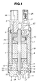
- FIG. 1 is a longitudinal cross-sectional view of a turbine fuel pump according to the first embodiment of the present invention.
- FIG. 2 is an enlarged view of a part of FIG. 1 including a pump housing, an impeller, etc.
- FIG. 3 is a cross-sectional view of the turbine fuel pump taken along line 3-3 of FIG. 2 which shows an inner housing as well as the impeller.
- FIG. 4 is an enlarged perspective view showing essential parts of vanes of the impeller.
- FIG. 5 is an enlarged plan view showing essential parts of the vane of the impeller.
- FIG. 6 is a characteristic curve showing a relationship between a length of a chamfer portion of the impeller and a pump efficiency.
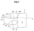
- FIG. 7 is a view similar to FIG. 5, but showing an impeller of a turbine fuel pump according to the second embodiment of the present invention.
- the fuel pump includes cylindrical casing 1 as an outer shell of the fuel pump. Opposite axial open ends of casing 1 are respectively closed by discharge cover 2 and pump housing 9 as described in detail later.
- Discharge cover 2 is of a bottom-closed cylindrical shape, and includes discharge port 2A and connector portion 2B both projecting outwardly from discharge cover 2, as well as bearing sleeve 2C formed at a center thereof so as to extend toward an inside of casing 1.
- Check valve 3 for retention of residual pressure is disposed within discharge port 2A.
- Check valve 3 is opened upon rotation of electric motor 7 as described later to discharge fuel flowing through casing 1 from discharge port 2A toward an external fuel conduit (not shown), etc.
- Check valve 3 is closed upon disenergization of electric motor 7 for preventing the fuel once discharged from casing 1 from returning back thereto to keep an inside of the fuel conduit under a given residual pressure.
- Rotating shaft 4 is supported so as to be rotatable about axis O-O within casing 1.
- Rotating shaft 4 extends along axis O-O shown in FIG. 2 and has an axial middle portion onto which rotor 7B of electric motor 7 as described later is mounted.
- Rotating shaft 4 may be constituted from a cylindrical metal rod.
- one axial end portion of rotating shaft 4 is rotatably supported by bearing sleeve 2C of discharge cover 2 through bushing 5.
- An opposite axial end portion of rotating shaft 4 is rotatably supported on an inner peripheral surface of lid 12B of inside housing 12 through busing 6.
- Rotating shaft 4 includes engaging shaft portion 4A which is integrally formed with the opposite axial end portion and projects outwardly beyond busing 6 into pump housing 9. Impeller 17 is secured to engaging shaft portion 4A.
- Engaging shaft portion 4A has a non-circular cross-section so as to prevent a relative rotation between engaging shaft portion 4A and impeller 17.
- Electric motor 7 is accommodated within casing 1 and engaged therewith at a position between discharge cover 2 and pump housing 9.
- Electric motor 7 includes cylindrical yoke 7A supporting a stator (not shown) made of a permanent magnet, rotor 7B and commutator 7C which are inserted into yoke 7A with a clearance and fitted onto rotational shaft 4 for a unitary rotation therewith, and a conductive brush (not shown) that comes into slide contact with commutator 7C.
- Pump housing 9 is fitted to one axial end portion of casing 1 in which engaging shaft portion 4A of rotational shaft 4 is located.
- Pump housing 9 accommodates impeller 17 having a generally disk shape.
- Pump housing 9 includes outer housing portion 10 and inner housing portion 12 that mate with each other in an axial direction of casing 1.
- Outer housing 10 serves for closing casing 1 from outside, and is engaged to casing 1 by a suitable method, for instance, caulking.
- Outer housing 10 is integrally formed with suction inlet 11 through which fuel is introduced into the fuel pump.
- Outer housing 10 further includes circular recess 10A located on a central side of impeller 17, and arcuate groove 10B located on an outer circumferential side of impeller 17.
- Circular recess 10A receives a tip end of engaging shaft portion 4A of rotational shaft 4.
- Arcuate groove 10B extends in a circumferential direction of a circle drawn around axis O-O and has a generally semi-circular section.
- Inner housing 12 is engaged in casing 1, and formed into a flat cylindrical body with a lid as shown in FIG. 2.
- Inner housing 12 includes cylindrical portion 12B mating with outer housing 10, and annular lid portion 12A closing one axial end of cylindrical portion 12B against casing 1.
- Cylindrical portion 12B has circular turbine recess 13 for accommodating impeller 17, on an inside surface thereof opposing to the mating surface of outer housing 10.
- Lid portion 12A has, on an inner peripheral side thereof, outlet port 14 extending therethrough in the axial direction of casing 1.
- Annular fuel path 15 formed along an outer periphery of turbine recess 13.
- Annular fuel path 15 includes arcuate groove 10B of outer housing 10.
- Annular fuel path 15 is in the form of a passage extending in a circumferential direction around axis O-O (axis center O) and having a generally elongated C-shape in section, as shown in FIG. 2.
- Annular fuel path 15 is communicated at a leading end thereof with suction port 11 and at a terminal end thereof with outlet port 14.
- Inner housing 12 is formed with arcuate seal partition wall 16 projecting radially inwardly from an inner periphery of cylindrical portion 12B up to a radially inward position close to an outer periphery of impeller 17.
- Seal partition wall 16 establishes a seal against the outer periphery of impeller 17 between suction port 11 and outlet port 14 except for the portion corresponding to fuel path 15.
- Impeller 17 is made of, for example, a reinforced plastic material, and rotatably accommodated within turbine recess 13 of pump housing 9. Impeller 17 is sealed between outer housing 10 and lid portion 12A of inner housing 12 in a floating fashion.
- Impeller 17 is driven by electric motor 7 via rotating shaft 4 so as to rotate around axis O-O (axis center O) in a direction indicated by arrow A in FIG. 3.
- the rotation of impeller 17 allows the fuel to be sucked from suction port 11 into fuel path 15 and delivered under pressure through fuel path 15 to outlet port 14.
- impeller 17 has engaging hole 17A which is engaged with engaging shaft portion 4A of rotating shaft 4 so as to prevent a relative rotation between rotating shaft 4 and impeller 17 and allow a unitary rotation thereof.
- Impeller 17 has a plurality of though holes 17B around engaging hole 17A in order to equalize fuel pressures on axially opposite sides of impeller 17. In this embodiment, three though holes 17B are provided.
- impeller 17 includes an annular body and a plurality of vanes 18 arranged along an outer periphery of the annular body. Vanes 18 project radially outwardly from the body of impeller 17 and are arranged in an equidistantly spaced relation to each other in a circumferential direction thereof.
- each of vanes 18 is in the form of a plate having a generally rectangular shape in section.
- Each of vanes 18 has a projecting end portion, namely, a tip end portion, arcuately bent forwardly in the rotational direction of impeller 17, namely, forwardly in direction A shown in FIG. 4.
- Vane 18 includes rectangular tip end face 18A extending circumferentially to define an outer peripheral surface of impeller 17, front face 18B located on a forward side relative to tip end face 18A in the rotational direction of impeller 17, rear face 18C located on a rearward side relative to tip end face 18A in the rotational direction of impeller 17, and a pair of side faces 18D located on axially opposite sides of impeller 17.
- front face 18B of vane 18 includes tip end portion 18B1 located on a side of the outer periphery of impeller 17, and root portion 18B2 located on a side of the body of impeller 17.
- Front face 18B is curved such that tip end portion 18B1 is forwardly positioned or advanced in the rotational direction of impeller 17 relative to root portion 18B2.
- vane 18 is formed into a so-called forward advanced vane.
- arcuate recesses 19 Formed between adjacent vanes 18 are a pair of arcuate recesses 19 which are arranged in back-to-back relation to each other in the axial direction of impeller 17. Only one of the pair of arcuate recesses 19 is shown in FIGS. 4 and 5. Each of arcuate recesses 19 has a mountain-like shape whose apex is located at the mid of axial length of impeller 17. Arcuate recess 19 has a radius of curvature which is substantially identical to that of an arcuate periphery of fuel path 15, namely, that of an arcuate wall surface of outer and inner housings 10 and 12 of pump housing 9 which defines the arcuate portion of fuel path 15 as shown in FIG. 2.
- Vane 18 further has, on a root side thereof, a pair of slant surfaces 20 formed on the axially opposite sides of impeller 17. Only one of the pair of slant surfaces 20 is shown in FIGS. 4 and 5. Each of slant surfaces 20 is formed by cutting a corner between rear face 18C and each of side faces 18D at an inclined angle relative thereto in order to allow the fuel to smoothly enter a space between adjacent vanes 18.
- vane 18 has chamfer portion 21 disposed between tip end face 18A and tip end portion 18B1 of front face 18B.
- Chamfer portion 21 is constituted by a flat surface formed by cutting a corner between tip end face 18A and tip end portion 18B1 of front face 18B.
- Chamfer portion 21 extends on a plane defined by line R extending radially outwardly from a center of rotation of impeller 17, namely, axis center O, and axis O-O of impeller 17. Namely, chamfer portion 21 is aligned with a plane containing axis O-O of impeller 17.
- chamfer portion 21 has length L as measured in section perpendicular to axis O-O. Length L of chamfer portion 21 uniformly extends between tip end face 18A and tip end portion 18B1 of front face 18B. Length L of chamfer portion 21 is defined according to the following formula based on experimental data shown in FIG. 6 as explained later: 0.05 ⁇ L ⁇ 0.15 (unit: mm) With the provision of chamfer portion 21 having length L within the range, the tip end of vane 18 can be formed into a break-free or hardly-broken shape, and a good pump efficiency can be maintained.
- the tip end of vane 18 of impeller 17 has a fully stable shape capable of withstanding an external force applied thereto. More specifically, a portion between tip end face 18A and front face 18B of vane 18 is formed into a non-acute-angled shape, i.e., a break-free or hardly-broken shape. Further, the formation of chamfer portion 21 gives substantially no adverse influence on the fuel flow within fuel path 15. Therefore, the pump efficiency is kept in a degree substantially identical to or slightly lower than that in the case where no chamfer portion 21 is provided.
- the thus arranged turbine fuel pump according to the first embodiment of the present invention is operated as follows.
- electric motor 7 When electric motor 7 is energized by supplying electric power thereto via connector 2B of discharge cover 2, rotor 7B is rotated together with rotating shaft 4, so that impeller 17 is rotatively driven within pump housing 9.
- the rotation of impeller 17 causes the fuel stored in a fuel tank (not shown) to be sucked into fuel path 15 through suction port 11 and then delivered under pressure through fuel path 15 by vanes 18 and finally discharged into casing 1 through discharge port 14.
- each of vanes 18 of impeller 17 has chamfer portion 21
- the tip end of vane 18 is free from cracking or breaking even when impeller 17 is exposed to various external forces during the process for production of the fuel pump. This results in promoted handing property thereof as well as simplified production process. Further, even upon operation of the fuel pump, each of vanes 18 can show an enhanced strength at the tip end thereof, thereby improving durability of impeller 17 that is subjected to high speed rotation.
- each of vanes 18 has front face 18B whose tip end portion 18B1 is forwardly positioned relative to root portion 18B2 thereof in the rotational direction of impeller 17, so that the acute-angled corner that tends to be cracked or broken will be formed between tip end portion 18B1 of front face 18B and tip end face 18A of vane 18.
- chamfer portion 21 is provided at the corner between tip end portion 18B1 of front face 18B and tip end face 18A. Vane 18 is thus formed into a break-free or hardly-broken shape.
- chamfer portion 21 when length L of chamfer portion 21 is adjusted to the range of 0.05 mm to 0.15 mm as measured in section perpendicular to axis O-O, the tip end of vane 18 can be formed into a fully stable shape capable of withstanding impact due to external force applied thereto, etc.
- the provision of chamfer portion 21 gives no significant influence on pump efficiency, and can therefore maintain a sufficiently high pump efficiency substantially identical to that in the case where no chamfer portion 21 is provided.
- chamfer portion 21 is formed into the flat surface along line R extending radially outwardly from the rotational center of impeller 17, namely, axis center O, a shape of a mold used for production of impeller 17 is more simplified as compared to that used in the case where a surface of the chamfer portion is inclined relative to line R.
- a turbine fuel pump according to a second embodiment of the present invention is explained hereinafter.
- the turbine fuel pump of the second embodiment is different from that of the first embodiment in that a chamfer portion is formed at an inclined angle relative to a plane containing a rotational axis of impeller. Therefore, like parts are represented by like numerals used in the first embodiments, and detailed explanations thereof are omitted.
- impeller 31 includes an annular body and a plurality of vanes 32 circumferentially arranged along an outer periphery of the body.
- vanes 32 is formed into a plate having a generally rectangular shape in section, and include tip end face 32A, front face 32B, rear face 32C and a pair of side faces 32D similarly to the first embodiment.
- Front face 32B includes tip end portion 32B1 and root portion 32B2.
- Formed between adjacent vanes 32 are a pair of arcuate recesses 33 arranged in back-to-back relation to each other in the axial direction of impeller 31.
- vane 32 has, on a root side thereof, a pair of slant surfaces 34 on axially opposite sides of impeller 31.
- Each of vanes 32 includes chamfer portion 35 disposed between tip end face 32A and tip end portion 32B1 of front face 32B.
- Chamfer portion 35 is formed into a flat surface by cutting a corner between tip end face 32A and tip end portion 32B1 of front face 32B in substantially the same manner as in the first embodiment.
- Chamfer portion 35 has uniform length L2 extending between tip end face 32A and tip end portion 32B1 of front face 32B and measured in section perpendicular to axis O-O. Length L2 may be in the range of 0.05 mm to 0.15 mm.
- Chamfer portion 35 is inclined at a predetermined angle relative to line R extending radially outwardly from the rotational center, namely, axis center O, of impeller 31.
- Chamfer portion 35 extends in a different direction from that of line R.
- chamfer portion 35 is inclined at the predetermined angle relative to a plane containing axis O-O of impeller 31.
- the thus arranged turbine fuel pump according to the second embodiment can provide substantially the same effects and functions as those of the first embodiment. Further, when length L2 of chamfer portion 35 formed in impeller 31 is controlled to a predetermined dimension, the pump efficiency can be more effectively prevented from being adversely affected by chamfer portion 35.
Landscapes
- Engineering & Computer Science (AREA)
- Mechanical Engineering (AREA)
- General Engineering & Computer Science (AREA)
- Structures Of Non-Positive Displacement Pumps (AREA)
Applications Claiming Priority (2)
| Application Number | Priority Date | Filing Date | Title |
|---|---|---|---|
| JP2003047287A JP4524349B2 (ja) | 2003-02-25 | 2003-02-25 | タービン型燃料ポンプ |
| JP2003047287 | 2003-02-25 |
Publications (3)
| Publication Number | Publication Date |
|---|---|
| EP1452738A2 true EP1452738A2 (fr) | 2004-09-01 |
| EP1452738A3 EP1452738A3 (fr) | 2005-11-02 |
| EP1452738B1 EP1452738B1 (fr) | 2007-11-21 |
Family
ID=32767713
Family Applications (1)
| Application Number | Title | Priority Date | Filing Date |
|---|---|---|---|
| EP04003913A Expired - Lifetime EP1452738B1 (fr) | 2003-02-25 | 2004-02-20 | Turbopompe pour carburant |
Country Status (5)
| Country | Link |
|---|---|
| US (2) | US7048494B2 (fr) |
| EP (1) | EP1452738B1 (fr) |
| JP (1) | JP4524349B2 (fr) |
| CN (1) | CN100339590C (fr) |
| DE (1) | DE602004010197T2 (fr) |
Cited By (4)
| Publication number | Priority date | Publication date | Assignee | Title |
|---|---|---|---|---|
| WO2006128762A1 (fr) * | 2005-06-01 | 2006-12-07 | Robert Bosch Gmbh | Groupe de transport |
| WO2007082009A3 (fr) * | 2006-01-11 | 2007-09-07 | Borgwarner Inc | Roue a aubes reduisant la pression et le courant |
| US7722311B2 (en) | 2006-01-11 | 2010-05-25 | Borgwarner Inc. | Pressure and current reducing impeller |
| DE102009021620B4 (de) | 2009-05-16 | 2021-07-29 | Pfeiffer Vacuum Gmbh | Vakuumpumpe |
Families Citing this family (7)
| Publication number | Priority date | Publication date | Assignee | Title |
|---|---|---|---|---|
| JP2007092659A (ja) * | 2005-09-29 | 2007-04-12 | Denso Corp | 流体ポンプ装置 |
| CN101666279B (zh) * | 2008-09-03 | 2014-02-19 | 德昌电机(深圳)有限公司 | 燃料泵 |
| DE102009021642B4 (de) | 2009-05-16 | 2021-07-22 | Pfeiffer Vacuum Gmbh | Vakuumpumpe |
| US9249806B2 (en) | 2011-02-04 | 2016-02-02 | Ti Group Automotive Systems, L.L.C. | Impeller and fluid pump |
| JP6038689B2 (ja) * | 2013-03-07 | 2016-12-07 | 愛三工業株式会社 | 回転体 |
| DE102013220668A1 (de) * | 2013-10-14 | 2015-04-16 | Continental Automotive Gmbh | Laufrad für eine insbesondere als Seitenkanalgebläse ausgebildete Seitenkanal-Strömungsmaschine |
| US10184475B2 (en) | 2015-07-20 | 2019-01-22 | Delphi Technologies Ip Limited | Fluid pump with flow impedance member |
Family Cites Families (12)
| Publication number | Priority date | Publication date | Assignee | Title |
|---|---|---|---|---|
| US2042499A (en) * | 1933-09-15 | 1936-06-02 | Roots Connersville Blower Corp | Rotary pump |
| US3899266A (en) * | 1972-12-18 | 1975-08-12 | Hitachi Ltd | Vortex blower |
| JP3060550B2 (ja) * | 1990-02-16 | 2000-07-10 | 株式会社デンソー | 車両用燃料ポンプ |
| US5372475A (en) * | 1990-08-10 | 1994-12-13 | Nippondenso Co., Ltd. | Fuel pump |
| JPH062690A (ja) * | 1992-04-03 | 1994-01-11 | Nippondenso Co Ltd | 燃料ポンプ |
| JP3307019B2 (ja) * | 1992-12-08 | 2002-07-24 | 株式会社デンソー | 再生ポンプ |
| US5762469A (en) * | 1996-10-16 | 1998-06-09 | Ford Motor Company | Impeller for a regenerative turbine fuel pump |
| DE69926144T2 (de) * | 1999-09-30 | 2006-05-18 | Mitsubishi Denki K.K. | Motorgetriebene brennstoffpumpe |
| DE10118416B4 (de) * | 2000-04-14 | 2013-07-04 | Denso Corporation | Kraftstoffpumpe für Verbrennungsmotor |
| JP2002339889A (ja) * | 2001-05-16 | 2002-11-27 | Enplas Corp | 円周流ポンプ用インペラ |
| US6974302B2 (en) * | 2002-06-06 | 2005-12-13 | Hitachi Unisia Automotive, Ltd. | Turbine fuel pump |
| US6932562B2 (en) * | 2002-06-18 | 2005-08-23 | Ti Group Automotive Systems, L.L.C. | Single stage, dual channel turbine fuel pump |
-
2003
- 2003-02-25 JP JP2003047287A patent/JP4524349B2/ja not_active Expired - Fee Related
-
2004
- 2004-02-20 EP EP04003913A patent/EP1452738B1/fr not_active Expired - Lifetime
- 2004-02-20 DE DE602004010197T patent/DE602004010197T2/de not_active Expired - Lifetime
- 2004-02-24 US US10/784,790 patent/US7048494B2/en not_active Expired - Fee Related
- 2004-02-25 CN CNB2004100066397A patent/CN100339590C/zh not_active Expired - Fee Related
-
2006
- 2006-03-17 US US11/377,314 patent/US7160079B2/en not_active Expired - Fee Related
Cited By (7)
| Publication number | Priority date | Publication date | Assignee | Title |
|---|---|---|---|---|
| WO2006128762A1 (fr) * | 2005-06-01 | 2006-12-07 | Robert Bosch Gmbh | Groupe de transport |
| WO2007082009A3 (fr) * | 2006-01-11 | 2007-09-07 | Borgwarner Inc | Roue a aubes reduisant la pression et le courant |
| US7425113B2 (en) | 2006-01-11 | 2008-09-16 | Borgwarner Inc. | Pressure and current reducing impeller |
| US7722311B2 (en) | 2006-01-11 | 2010-05-25 | Borgwarner Inc. | Pressure and current reducing impeller |
| CN101371048B (zh) * | 2006-01-11 | 2011-10-05 | 博格华纳公司 | 减小压力和电流的叶轮 |
| CN101535655B (zh) * | 2006-11-30 | 2012-07-04 | 博格华纳公司 | 减小压力和电流的叶轮 |
| DE102009021620B4 (de) | 2009-05-16 | 2021-07-29 | Pfeiffer Vacuum Gmbh | Vakuumpumpe |
Also Published As
| Publication number | Publication date |
|---|---|
| DE602004010197T2 (de) | 2008-09-25 |
| US20040165981A1 (en) | 2004-08-26 |
| JP2004257284A (ja) | 2004-09-16 |
| DE602004010197D1 (de) | 2008-01-03 |
| US7048494B2 (en) | 2006-05-23 |
| CN100339590C (zh) | 2007-09-26 |
| EP1452738A3 (fr) | 2005-11-02 |
| CN1525059A (zh) | 2004-09-01 |
| US20060159546A1 (en) | 2006-07-20 |
| US7160079B2 (en) | 2007-01-09 |
| JP4524349B2 (ja) | 2010-08-18 |
| EP1452738B1 (fr) | 2007-11-21 |
Similar Documents
| Publication | Publication Date | Title |
|---|---|---|
| US5122039A (en) | Electric-motor fuel pump | |
| EP1452738B1 (fr) | Turbopompe pour carburant | |
| US5219277A (en) | Electric-motor fuel pump | |
| JPH0472078B2 (fr) | ||
| CN102483059A (zh) | 电动泵单元 | |
| GB2263311A (en) | Electric fuel pump. | |
| JP2003129966A (ja) | 電動オイルポンプ | |
| CN1176681A (zh) | 输送燃料的装置 | |
| US20030118438A1 (en) | Fuel pump | |
| US6524078B1 (en) | Pond pump with reversing means to prevent rotation in the opposite direction | |
| US6336788B1 (en) | Regenerative type pumps | |
| JP2004507666A (ja) | 燃料を搬送するためのユニット | |
| KR100524339B1 (ko) | 터빈 연료 펌프 | |
| US20030118437A1 (en) | Fuel pump | |
| CN111749883B (zh) | 油泵 | |
| CN219691763U (zh) | 一种泵 | |
| JP4205475B2 (ja) | タービン型燃料ポンプ | |
| JP7185606B2 (ja) | 燃料ポンプ | |
| JP3591091B2 (ja) | 再生ポンプ | |
| JP7052524B2 (ja) | インペラ及び流体ポンプ | |
| KR100662806B1 (ko) | 자동차용 전동기식 연료펌프 | |
| GB1561426A (en) | Rotary fuel-pumps | |
| KR200403311Y1 (ko) | 자동차용 전동기식 연료펌프 | |
| TW202603276A (zh) | 馬達泵浦 | |
| JP2004011555A (ja) | タービン型燃料ポンプ |
Legal Events
| Date | Code | Title | Description |
|---|---|---|---|
| PUAI | Public reference made under article 153(3) epc to a published international application that has entered the european phase |
Free format text: ORIGINAL CODE: 0009012 |
|
| 17P | Request for examination filed |
Effective date: 20040220 |
|
| AK | Designated contracting states |
Kind code of ref document: A2 Designated state(s): AT BE BG CH CY CZ DE DK EE ES FI FR GB GR HU IE IT LI LU MC NL PT RO SE SI SK TR |
|
| AX | Request for extension of the european patent |
Extension state: AL LT LV MK |
|
| RAP1 | Party data changed (applicant data changed or rights of an application transferred) |
Owner name: HITACHI, LTD. |
|
| PUAL | Search report despatched |
Free format text: ORIGINAL CODE: 0009013 |
|
| AK | Designated contracting states |
Kind code of ref document: A3 Designated state(s): AT BE BG CH CY CZ DE DK EE ES FI FR GB GR HU IE IT LI LU MC NL PT RO SE SI SK TR |
|
| AX | Request for extension of the european patent |
Extension state: AL LT LV MK |
|
| RIC1 | Information provided on ipc code assigned before grant |
Ipc: 7F 04D 29/18 B Ipc: 7F 04D 5/00 A |
|
| AKX | Designation fees paid |
Designated state(s): DE FR |
|
| GRAP | Despatch of communication of intention to grant a patent |
Free format text: ORIGINAL CODE: EPIDOSNIGR1 |
|
| GRAS | Grant fee paid |
Free format text: ORIGINAL CODE: EPIDOSNIGR3 |
|
| GRAA | (expected) grant |
Free format text: ORIGINAL CODE: 0009210 |
|
| AK | Designated contracting states |
Kind code of ref document: B1 Designated state(s): DE FR |
|
| REF | Corresponds to: |
Ref document number: 602004010197 Country of ref document: DE Date of ref document: 20080103 Kind code of ref document: P |
|
| ET | Fr: translation filed | ||
| PGFP | Annual fee paid to national office [announced via postgrant information from national office to epo] |
Ref country code: FR Payment date: 20080219 Year of fee payment: 5 |
|
| PLBE | No opposition filed within time limit |
Free format text: ORIGINAL CODE: 0009261 |
|
| STAA | Information on the status of an ep patent application or granted ep patent |
Free format text: STATUS: NO OPPOSITION FILED WITHIN TIME LIMIT |
|
| 26N | No opposition filed |
Effective date: 20080822 |
|
| REG | Reference to a national code |
Ref country code: FR Ref legal event code: ST Effective date: 20091030 |
|
| PG25 | Lapsed in a contracting state [announced via postgrant information from national office to epo] |
Ref country code: FR Free format text: LAPSE BECAUSE OF NON-PAYMENT OF DUE FEES Effective date: 20090302 |
|
| PGFP | Annual fee paid to national office [announced via postgrant information from national office to epo] |
Ref country code: DE Payment date: 20160216 Year of fee payment: 13 |
|
| REG | Reference to a national code |
Ref country code: DE Ref legal event code: R119 Ref document number: 602004010197 Country of ref document: DE |
|
| PG25 | Lapsed in a contracting state [announced via postgrant information from national office to epo] |
Ref country code: DE Free format text: LAPSE BECAUSE OF NON-PAYMENT OF DUE FEES Effective date: 20170901 |