EP1452880B1 - Appareil de mesure du taux spécifique d'absorption d'un appareil de radiocommunication - Google Patents
Appareil de mesure du taux spécifique d'absorption d'un appareil de radiocommunication Download PDFInfo
- Publication number
- EP1452880B1 EP1452880B1 EP04004310A EP04004310A EP1452880B1 EP 1452880 B1 EP1452880 B1 EP 1452880B1 EP 04004310 A EP04004310 A EP 04004310A EP 04004310 A EP04004310 A EP 04004310A EP 1452880 B1 EP1452880 B1 EP 1452880B1
- Authority
- EP
- European Patent Office
- Prior art keywords
- magnetic field
- antenna
- distribution
- sar
- minute
- Prior art date
- Legal status (The legal status is an assumption and is not a legal conclusion. Google has not performed a legal analysis and makes no representation as to the accuracy of the status listed.)
- Expired - Lifetime
Links
- 238000004891 communication Methods 0.000 title claims description 45
- 238000010521 absorption reaction Methods 0.000 title claims description 20
- 238000009826 distribution Methods 0.000 claims description 111
- 238000005259 measurement Methods 0.000 claims description 85
- 238000000034 method Methods 0.000 claims description 30
- 238000004364 calculation method Methods 0.000 claims description 18
- 230000009466 transformation Effects 0.000 claims description 13
- 239000004020 conductor Substances 0.000 claims description 10
- 230000005855 radiation Effects 0.000 claims description 5
- 239000000523 sample Substances 0.000 description 43
- 230000007246 mechanism Effects 0.000 description 18
- 239000000758 substrate Substances 0.000 description 18
- 238000004458 analytical method Methods 0.000 description 12
- 230000005684 electric field Effects 0.000 description 12
- 238000010586 diagram Methods 0.000 description 9
- 239000011347 resin Substances 0.000 description 8
- 229920005989 resin Polymers 0.000 description 8
- FAPWRFPIFSIZLT-UHFFFAOYSA-M Sodium chloride Chemical compound [Na+].[Cl-] FAPWRFPIFSIZLT-UHFFFAOYSA-M 0.000 description 4
- 230000005672 electromagnetic field Effects 0.000 description 4
- 239000007788 liquid Substances 0.000 description 4
- 238000012545 processing Methods 0.000 description 4
- 230000007423 decrease Effects 0.000 description 3
- 238000001514 detection method Methods 0.000 description 3
- 239000004925 Acrylic resin Substances 0.000 description 2
- 229920000178 Acrylic resin Polymers 0.000 description 2
- 239000003990 capacitor Substances 0.000 description 2
- 230000008859 change Effects 0.000 description 2
- 238000007796 conventional method Methods 0.000 description 2
- 239000008367 deionised water Substances 0.000 description 2
- 229910021641 deionized water Inorganic materials 0.000 description 2
- 238000005516 engineering process Methods 0.000 description 2
- 230000004907 flux Effects 0.000 description 2
- 238000004519 manufacturing process Methods 0.000 description 2
- 238000012986 modification Methods 0.000 description 2
- 230000004048 modification Effects 0.000 description 2
- -1 polytetrafluoroethylene Polymers 0.000 description 2
- 239000004810 polytetrafluoroethylene Substances 0.000 description 2
- 229920001343 polytetrafluoroethylene Polymers 0.000 description 2
- 230000035945 sensitivity Effects 0.000 description 2
- 239000011780 sodium chloride Substances 0.000 description 2
- XLYOFNOQVPJJNP-UHFFFAOYSA-N water Chemical compound O XLYOFNOQVPJJNP-UHFFFAOYSA-N 0.000 description 2
- 239000002023 wood Substances 0.000 description 2
- OAYXUHPQHDHDDZ-UHFFFAOYSA-N 2-(2-butoxyethoxy)ethanol Chemical compound CCCCOCCOCCO OAYXUHPQHDHDDZ-UHFFFAOYSA-N 0.000 description 1
- 102100031491 Arylsulfatase B Human genes 0.000 description 1
- RYGMFSIKBFXOCR-UHFFFAOYSA-N Copper Chemical compound [Cu] RYGMFSIKBFXOCR-UHFFFAOYSA-N 0.000 description 1
- 101000923070 Homo sapiens Arylsulfatase B Proteins 0.000 description 1
- XUIMIQQOPSSXEZ-UHFFFAOYSA-N Silicon Chemical compound [Si] XUIMIQQOPSSXEZ-UHFFFAOYSA-N 0.000 description 1
- CZMRCDWAGMRECN-UGDNZRGBSA-N Sucrose Chemical compound O[C@H]1[C@H](O)[C@@H](CO)O[C@@]1(CO)O[C@@H]1[C@H](O)[C@@H](O)[C@H](O)[C@@H](CO)O1 CZMRCDWAGMRECN-UGDNZRGBSA-N 0.000 description 1
- 229930006000 Sucrose Natural products 0.000 description 1
- 230000033228 biological regulation Effects 0.000 description 1
- 230000001413 cellular effect Effects 0.000 description 1
- 239000001913 cellulose Substances 0.000 description 1
- 229920002678 cellulose Polymers 0.000 description 1
- 229910052802 copper Inorganic materials 0.000 description 1
- 239000010949 copper Substances 0.000 description 1
- 230000005674 electromagnetic induction Effects 0.000 description 1
- 238000011156 evaluation Methods 0.000 description 1
- 230000002070 germicidal effect Effects 0.000 description 1
- 125000002887 hydroxy group Chemical group [H]O* 0.000 description 1
- 238000002955 isolation Methods 0.000 description 1
- 239000000463 material Substances 0.000 description 1
- 230000035699 permeability Effects 0.000 description 1
- 238000005070 sampling Methods 0.000 description 1
- 229910052710 silicon Inorganic materials 0.000 description 1
- 239000010703 silicon Substances 0.000 description 1
- 239000005720 sucrose Substances 0.000 description 1
- 230000001360 synchronised effect Effects 0.000 description 1
- 230000002123 temporal effect Effects 0.000 description 1
- 238000009827 uniform distribution Methods 0.000 description 1
Images





Classifications
-
- G—PHYSICS
- G01—MEASURING; TESTING
- G01R—MEASURING ELECTRIC VARIABLES; MEASURING MAGNETIC VARIABLES
- G01R29/00—Arrangements for measuring or indicating electric quantities not covered by groups G01R19/00 - G01R27/00
- G01R29/08—Measuring electromagnetic field characteristics
- G01R29/0807—Measuring electromagnetic field characteristics characterised by the application
- G01R29/0814—Field measurements related to measuring influence on or from apparatus, components or humans, e.g. in ESD, EMI, EMC, EMP testing, measuring radiation leakage; detecting presence of micro- or radiowave emitters; dosimetry; testing shielding; measurements related to lightning
- G01R29/0857—Dosimetry, i.e. measuring the time integral of radiation intensity; Level warning devices for personal safety use
-
- G—PHYSICS
- G01—MEASURING; TESTING
- G01R—MEASURING ELECTRIC VARIABLES; MEASURING MAGNETIC VARIABLES
- G01R29/00—Arrangements for measuring or indicating electric quantities not covered by groups G01R19/00 - G01R27/00
- G01R29/08—Measuring electromagnetic field characteristics
- G01R29/0864—Measuring electromagnetic field characteristics characterised by constructional or functional features
- G01R29/0878—Sensors; antennas; probes; detectors
Definitions
- the present invention relates to an apparatus for measuring a specific absorption rate (hereinafter, referred to as an "SAR"), and in particular, to an apparatus for measuring an SAR of a radio communication apparatus such as a mobile phone, a portable radio communication apparatus, or the like.
- SAR specific absorption rate
- an SAR is provided.
- an SAR estimation method for calculating an electric current distribution from an incident magnetic field on the surface of the phantom when an electromagnetic wave is radiated from an antenna to obtain the SAR distribution in, for example, the Japanese Patent No. 2790103 , application publication number JP 09-166554 .
- the magnetic field is detected by a magnetic field detecting probe that includes movement and rotation mechanisms, then the electric current distribution of the antenna is thereby estimated, and the SAR is evaluated from this electric current distribution.
- the SAR is measured with the mobile phone closely attached to the phantom.
- the incident magnetic field on the surface of the phantom is measured. Due to this, the magnetic field cannot be measured while the mobile phone is arranged in accordance with the actual SAR measurement. It is, therefore, disadvantageously impossible to check the SAR of the mobile phone on the production line by the conventional SAR measuring apparatus or method.
- the SAR of the portable radio communication apparatus is measured while the apparatus is closely attached to the head of the human body. For this reason, an actual surface magnetic field cannot be measured, and an error is generated in the measured SAR.
- an ordinary dipole antenna, or the like is employed as a reference antenna, a part having a low magnetic field intensity locally may be caused, and magnetic field detection precision is deteriorated. As a result, an SAR estimation error is disadvantageously generated.
- an apparatus for measuring a specific absorption rate (SAR) of a radio communication apparatus referred to as a SAR measuring apparatus hereinafter.
- a first measurement device measures in free space a first near magnetic field distribution of a radio wave radiated from an array antenna of a reference antenna including a plurality of minute antennas
- a second measurement device measures a specific absorption rate (SAR) distribution with respect to the radio wave radiated from the array antenna, with a predetermined phantom using a predetermined measuring method.
- a first calculation device calculates a distribution of a transformation coefficient ⁇ by dividing the measured specific absorption rate (SAR) distribution by a square of the measured first near magnetic field distribution
- a third measurement device measures in free space a second near magnetic field distribution of a radio wave radiated from a radio communication apparatus to be measured
- a second calculation device estimates and calculates a specific absorption rate (SAR) distribution with respect to the radio wave radiated from the radio communication apparatus to be measured, by multiplying a square of the measured second near magnetic field distribution by the calculated distribution of the transformation coefficient ⁇ .
- the minute antennas are preferably minute dipole antennas.
- the array antenna is preferably formed by arranging a plurality of minute antennas in a one-dimensional array on a plane along a shape of a side surface of a head of a human body.
- the array antenna is preferably formed by arranging a plurality of minute antennas in a two-dimensional array on a plane along a shape of a side surface of a head of a human body.
- the array antenna is preferably formed by arranging a plurality of minute antennas at an equal antenna interval "d".
- the plurality of minute antennas are preferably arranged in the array antenna so that the antenna interval "d" satisfies d ⁇ 1.1 h when a measurement interval between the array antenna and the first measurement device is "h".
- a plurality of minute antennas is preferably arranged in the array antenna so that the antenna interval "d" satisfies d ⁇ 1.3 h when a measurement interval between the array antenna and the first measurement device is "h”.
- the array antenna is preferably arranged so that main beams from the plurality of minute antennas are parallel to each other.
- the array antenna is preferably arranged so that main beams from the minute antennas adjacent,to each other among the plurality of minute antennas are orthogonal to each other.
- an SAR measuring apparatus In the SAR measuring apparatus, a first measurement device measures in free space a first near magnetic field distribution of a radio wave radiated from a flat-plane-shaped dipole antenna of a reference antenna, and a second measurement device measures a specific absorption rate (SAR) distribution with respect to the radio wave radiated from the flat-plane-shaped dipole antenna, with a predetermined phantom using a predetermined measuring method.
- SAR specific absorption rate
- a first calculation device calculates a distribution of a transformation coefficient ⁇ by dividing the measured specific absorption rate (SAR) distribution by a square of the measured first near magnetic field distribution
- a third measurement device measures in free space a second near magnetic field distribution of a radio wave radiated from a radio communication apparatus to be measured
- a second calculation device estimates and calculates a specific absorption rate (SAR) distribution with respect to the radio wave radiated from the radio communication apparatus to be measured, by multiplying a square of the measured second near magnetic field distribution by the calculated distribution of the transformation coefficient ⁇ .
- the flat-plane-shaped dipole antenna preferably includes two rectangular radiation conductors having sizes different from each other to be formed so that a feeding point is excluded from a range of a near magnetic field measurement.
- the above-mentioned SAR measuring apparatus preferably includes an impedance matching circuit connected with the flat-plane-shaped dipole antenna, and the impedance matching circuit makes an impedance matching between a feeding line and the flat-plane-shaped dipole antenna.
- the near magnetic field distribution and the SAR distribution are measured using as the reference antenna the minute array antenna including a plurality of minute antennas or a flat-plane-shaped dipole antenna, and then the magnetic field distribution in free space of the portable radio communication apparatus is measured. It is thereby possible to estimate the SAR distribution by quite a simpler method with higher precision, as compared with the prior art.
- Fig. 1 is a perspective view and a block diagram which illustrate a magnetic field measuring apparatus of an SAR measurement system according to a first preferred embodiment of the present invention.
- Fig. 2 is a perspective view and a block diagram which illustrate an SAR measuring apparatus of the SAR measurement system according to the first preferred embodiment of the present invention.
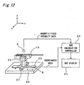
- Fig. 12 is a perspective view and a block diagram which illustrate a configuration of the SAR measurement system according to the preferred embodiment of the present invention.
- Fig. 13 is a flow chart which illustrates an SAR distribution calculation processing executed by an SAR calculation controller 20 shown in Fig. 12 .
- An SAR distribution calculation method is characterized by executing an SAR distribution calculation processing shown in Fig. 13 using a minute dipole array antenna 1A including nine minute dipole antennas 1-1 to 1-9, and using the SAR measurement system shown in Figs. 1, 2 , and 12 .
- an SAR distribution is estimated in free space while paying attention to the high correlation between the SAR and the magnetic field.
- a magnetic field intensity distribution H ref (x, y) of a radio wave radiated from the reference antenna is measured, and an SAR distribution SAR(x, y) with respect to the radio wave radiated from the reference antenna is measured using a predetermined phantom.
- a coefficient determined by a ratio of a square of the measured magnetic field intensity distribution H ref to the measured SAR distribution SAR ref is calculated at each of the two-dimensional measurement points in an xy coordinate system.
- a magnetic field intensity distribution H measure (x, y) of the portable radio communication apparatus to be measured is measured in free space.
- a method for measuring a near magnetic field distribution H ref (x, y) of the radio wave radiated from the minute dipole array antenna 1A of a reference antenna will be next described.
- the minute dipole array antenna 1A constituted by arranging the nine minute dipole antennas 1-1 to 1-9 (generically denoted by numerical reference 1) at an equal interval in two-dimensional array (on the assumption that a distance between centers of the two adjacent minute dipole antennas is "d" as shown in Fig. 3 ), for example.
- Each of the minute dipole antennas 1 is preferably a length which is equal to or larger than 0.01 wavelength and is equal to or smaller than 0.2 wavelength, more preferably a length which is equal to or larger than 0.01 wavelength and is equal to or smaller than 0.1 wavelength, and still more preferably a length which is equal to or larger than 0.02 wavelength and is equal to or smaller than 0.1 wavelength.
- the respective minute dipole antennas 1-1 to 1-9 are supported by a dielectric substrate 3, and are connected with radio signal generators 2-1 to 2-9, respectively, that generate radio signals having the same frequency and the same phase as each other, where the generated radio signals are synchronized based on a reference radio signal from a single oscillator (not shown) using, for example, a PLL circuit.
- the radio signals generated by the radio signal generators 2-1 to 2-9 are supplied to the minute dipole antennas 1-1 to 1-9, and radio waves corresponding to the radio signals are radiated from the minute dipole antennas 1-1 to 1-9, respectively, then this leads to obtaining a substantially uniform magnetic field distribution near the minute dipole array antenna 1A.
- a magnetic field detecting probe 4 using, for example, a circular loop antenna is scanned in two dimensions in the x and y directions by a scanning mechanism 4S. Then, the near magnetic field distribution H ref (x, y) is measured in free space using a magnetic field measuring unit 4A by means of a predetermined method which has been known to those skilled in the art (this method uses such a principle that an electric current flowing in the magnetic field detecting probe 4 is proportional to the magnetic field), based on a detection signal from the magnetic field detecting probe 4.
- a method for measuring the SAR distribution SAR ref (x, y) with respect to the radio wave radiated from the minute dipole array antenna 1A of the reference antenna will be further described.
- a phantom filled with an SAR liquid 6 having a predetermined composition is used as a human head phantom 5 made of, for example, a material mainly consisting of silicon resin and having a shape of a human head.
- An electric field detecting probe 7 is scanned in the two dimensions in the x and y directions along an inner wall surface of the human head phantom 5.
- the SAR distribution SAR ref (x, y) is measured using an SAR measuring unit 7A by means of a predetermined method which has been known to those skilled in the art (this method uses such a principle that a voltage induced by the magnetic field detecting probe 4 is proportional to the electric field and that a square of the electric field is proportional to the SAR as expressed by the Equation (1)) based on a detection signal from the electric field detecting probe 7.
- the SAR liquid 6 there is used a liquid that, for example, consists of 56.5% of sucrose, 40.92% of deionized water, 1.48% of sodium chloride, 1.0% of hydroxyl cellulose, and 0.1% of germicide at the frequency "f" of 900 MHz.
- a liquid that, for example, consists of 44.92% of butyl Carbitol, 54.90% of deionized water, and 0.18% of sodium chloride.
- the percentage of the composition means volume percentage.
- the nine minute dipole antennas 1-1 to 1-9 are arranged as one example in a two-dimensional array of three by three.
- the present invention is not limited to this, and a plurality of minute dipole antennas may be arranged in either a one-dimensional array or a two-dimensional array.
- Fig. 3 is a plan view which illustrates an arrangement of the minute dipole array antenna used in the SAR measurement system according to the first preferred embodiment of the present invention.
- the arrangement of the minute dipole antennas 1 for forming a uniform magnetic field distribution, a substantially uniform magnetic field distribution, or a magnetic field distribution near the uniform distribution will be now described.
- an instance of arranging the five minute dipole antennas 1-1 to 1-5 at the equal interval "d" on the x axis, as shown in Fig. 3 will be described. This is intended to consider an influence of the minute dipole antenna 1 arranged outward of the adjacent minute dipole antenna 1.
- the minute dipole antennas 1-1 to 1-5 are arranged at the equal interval "d". Besides, the minute dipole antennas 1-1 to 1-5 are arranged so that longitudinal directions of the antennas 1-1 to 1-5 are parallel to the x direction.
- a difference between the maximum and minimum magnetic field intensities in a section (shown at an upper part of Fig. 3 ) having the interval "d" about a coordinate position of the minute dipole antenna 1-3 located at the center of the section is calculated by means of a analysis method which has been known to those skilled in the art, and a result of the calculation.
- the purpose of the analysis is to determine the interval "d" for forming the substantially uniform magnetic field distribution.
- the analysis is performed while setting a measurement interval "h" (that is the measurement interval between each minute dipole antenna 1 and the magnetic field detecting probe 4) at 2 [mm], 3 [mm], and 5 [mm].
- the frequency of radio wave used in the analysis is 900 MHz. It is noted that radio waves of the radio signals having the same frequency and the same phase are radiated from the respective minute dipole antennas 1-1 to 1-5.
- a length L of each minute dipole antenna 1 is set to 1 [mm].
- Fig. 6 is a graph which illustrates analysis results when the minute dipole array antenna shown in Fig. 3 is used, and which illustrates a difference between the maximum and minimum magnetic field intensities with a measurement width "d" with a center of a coordinate position of the minute dipole antenna 1-3 for the antenna interval "d" with the measurement interval "h” set as a parameter.
- the vertical axis is a difference between the maximum and minimum magnetic field intensities (referred to as a magnetic field intensity difference hereinafter) in the measurement width "d" with a center of a coordinate position of the minute dipole antenna 1-3 located at the center.
- the magnetic field intensity difference is indicated by a percentage with respect to an average in the measurement width "d" of the interval. Namely, the antenna interval "d" is set to be equal to the measurement width "d".
- the measurement width "d" is 2.6 [mm] and the difference between the maximum and minimum magnetic field intensities is about 10 [%].
- the difference between the maximum and minimum magnetic field intensities is equal to or smaller than 5 [%]. Therefore, the magnetic field intensity distribution obtained from the analysis result can be considered to be sufficiently uniform.
- the measurement width "d" satisfies a relationship of d ⁇ 3.3 [mm] and the magnetic field difference is within 5 [%].
- the measurement width "d” satisfies a relationship of d ⁇ 5.5 [mm] and the magnetic field difference is within 5 [%]. It can be seen from this that the measurement width "d” should be set to satisfy a relationship of d ⁇ 1.1 h with respect to the measurement interval "h” in order to fall the magnetic field intensity difference within 5 [% ⁇ . Further, it can be seen that the measurement width "d” should be set to 1.3 times or less of the measurement interval "h” in order to fall the magnetic field intensity difference within 10 [%].
- the maximum value of the measurement width "d" is determined.
- the maximum value of the measurement interval "h" cannot be determined from the Equation (5) or (6) and the Equation (7) but determined from a received electric power of the probe as follows.
- Fig. 4 is a front view for illustrating a relationship among a length "d" of a side of a loop, a height "h" of a magnetic field H, and the wavelength ⁇ when the minute square loop probe 4p is used as the magnetic field detecting probe 4 shown in Fig. 1 .
- the maximum value of the loop probe 4p is a scanning interval of the magnetic field detecting probe 4. As the size of the magnetic field detecting probe 4 is larger, the sensitivity of the probe 4 becomes higher but the resolution of the probe 4 becomes lower. For this reason, the resolution of the magnetic field detecting probe 4 needs to be at least the resolution capable of resolving the scanning interval.
- V ⁇ 0 / 2 ⁇ ⁇ h ⁇ d 2 dI / dt
- Equation (20) h ⁇ ⁇ 0 ⁇ I 0 ⁇ d 2 / ⁇ ⁇ k B ⁇ B ⁇ T ⁇ Z 1 / 2
- Fig. 5 is a front view showing a relationship among the length "d" of the minute dipole probe, the height "h” of the magnetic field H, and the wavelength ⁇ , when the minute dipole probe 7p is used as the magnetic field detecting probe 4 shown in Fig. 1 .
- the maximum length of the minute dipole is the scanning interval of the magnetic field detecting probe 4. As the size of the magnetic field detecting probe 4 is larger, the sensitivity of the probe 4 becomes higher but the resolution of the probe 4 is lower.
- the resolution of the magnetic field detecting probe 4 is at least the resolution capable of resolving the scanning interval.
- Equation (28) h ⁇ ⁇ ⁇ I 0 ⁇ d / 2 ⁇ ⁇ ⁇ k B ⁇ B ⁇ T ⁇ Z 1 / 2
- Equation (29) an input electric power P in of the line conductor Cs is expressed by the following Equation (29).
- Equation (30) may be assigned to the above-mentioned conditional Equation (Equation (5) or (6)).
- the electric power and the impedance are often known, for example, the input electric power of the antenna is 10 dBm and the impedance is 50 ⁇ .
- Fig. 7 is a graph which illustrates analysis results when the minute dipole array antenna shown in Fig. 3 is used, and which illustrates the magnetic field intensity difference with respect to the antenna length L.
- the antenna interval "d" of the minute dipole antennas 1 is 2 [mm] and the measurement interval "h” is 2 [mm], and further, the length L is changed from 0.1 to 1.9 [mm].
- the length L of the minute dipole antenna 1 is not limited to a specific value but may be such that the adjacent antennas do not contact with each other.
- Fig. 8 is a plan view which illustrates an arrangement of the array antenna that includes 21 minute dipole antennas 1-1 to 1-21.
- the length L of each of the minute dipole antennas 1-1 to 1-21 is set to 1 [mm] and the measurement interval "h" is set to 5 [mm].
- Fig. 9 is a graph which illustrates analysis results when the array antenna shown in Fig. 8 is used, and which illustrates a normalized magnetic field intensity normalized to the maximum magnetic field intensity with respect to the x coordinate.
- the magnetic field intensity difference for the maximum magnetic intensity is within 10 [%] in a range of 5 [mm] ⁇ x ⁇ 95 [mm], and within 5 [%] in a range of 10 [mm] ⁇ x ⁇ 90 [mm]. It can be seen from this that the substantially uniform magnetic field distribution can be obtained in a wider range.
- the minute dipole antennas 1 by arranging the minute dipole antennas 1 at the antenna interval "d" in the two-dimensions, it is possible to generate the uniform magnetic field distribution in the two-dimensions.
- the directions of the minute dipole antennas 1 are all set to one direction in parallel to each other.
- Fig. 10 is a plan view which illustrates an array antenna that includes four minute dipole antennas according to a first modified preferred embodiment of the present invention.
- longitudinal directions of the respective minute dipole antennas 1 are parallel to each other, and the main beams from the respective minute dipole antennas 1 are parallel to each other, as well.
- the first modified preferred embodiment since the magnetic field intensity decreases on end portions of the array antenna, it is necessary to set the range of arranging the respective minute dipole antennas 1 to be slightly larger than at least the range of arranging the portable radio communication apparatus used for the measurement.
- Fig. 11 is a plan view which illustrates an arrangement of an array antenna that includes four minute dipole antennas according to a second modified preferred embodiment of the present invention.
- the minute dipole antennas 1 may be arranged so that the adjacent minute dipole antennas 1 are orthogonal to each other as shown in Fig. 11 in order to maintain isolation of the adjacent minute dipole antennas 1 from each other.
- the main beams from the minute dipole antennas 1 are parallel to each other. It is thereby possible to generate a uniform magnetic field containing two components orthogonal to each other.
- Fig. 12 is a perspective view and a block diagram which illustrate a configuration of an SAR measurement system according to a preferred embodiment of the present invention.
- an x stage 31 movable in the x direction and a y stage 32 movable in the y direction are provided on a support base 30, a rectangular support column 9 extending vertically from the stages 31 and 32 is provided, and a fixed support section 33 is provided on an upper end portion of the support column 9.
- a portable radio communication apparatus 10 to be measured is sandwiched by the fixed support section 33 so as to be fixedly supported by the fixed support section 33.
- the portable radio communication apparatus 10 can be moved in the x direction.
- the portable radio communication apparatus 10 can be moved in the y direction. It is thereby possible to move the portable radio communication apparatus 10 in the x and y directions, i.e., in the two dimensions, relative to the fixed magnetic field detecting probe 4.
- the coordinates data from the x stage 31 and the y stage 32 are inputted to the SAR calculation controller 20, and magnetic field intensity data detected by the magnetic field detecting probe 4 is inputted to the SAR calculation controller 20.
- step S1 of Fig. 13 the minute dipole array antenna 1A of a reference antenna is excited by the radio signals having the same frequency and the same phase as each other, thereby radiating a radio wave from the minute dipole array antenna 1A.
- the near magnetic field distribution H ref (x, y) of the radiated radio wave is measured in free space using the magnetic field scanning probe 4 which is apart from the minute dipole array antenna 1A by a certain distance and which is scanned in the x and y directions, i.e., in the two-dimensions.
- step S2 the minute dipole array antenna 1A is excited in a manner similar to that of step S1, thereby radiating the radio wave from the minute dipole array antenna 1A.
- the SAR distribution SAR ref (x, y) with respect to the radio wave is measured with the human head phantom 5 using the electric field detecting probe 7 which is scanned in the x and y directions, i.e., in the two-dimensions along the inner wall surface of the phantom 5.
- the transformation coefficient distribution ⁇ (x, y) is calculated using the Equation (3) based on the measured magnetic field distribution H ref (x, y) and the measured SAR ref (x, y) of the minute dipole array antenna 1A.
- step S4 the portable radio communication apparatus to be measured is excited, thereby radiating the radio wave from the portable radio communication apparatus.
- the near magnetic field distribution H measure (x, y) of the radiated radio wave is measured in free space using the magnetic field detecting probe 4 which is scanned in the x and y directions, i.e., in the two-dimensions.
- the SAR distribution SAR calculate (x, y) of the portable radio communication apparatus is calculated using the Equation (4) based on the magnetic field distribution H measure (x, y) measured in step S5 and the transformation coefficient ⁇ (x, y) calculated in step S3, and then the calculated SAR distribution SAR calculate (x, y) is displayed on a CRT display 21.
- a denominator is the square of the magnetic field distribution H ref (x, y). Due to this, when the value of the magnetic field distribution H ref (x, y) is smaller, the measurement error of the SAR distribution SAR ref (x, y) is larger. Accordingly, the error may be possibly caused in the SAR distribution SAR calculate (x, y) calculated using the Equation (4). Nevertheless, by using the minute dipole array antenna 1A arranged to obtain the uniform or substantially uniform magnetic field distribution, the transformation coefficient ⁇ (x, y) can be calculated, and the measurement precision upon measuring the SAR distribution of the portable radio communication apparatus can be improved, as compared with the prior art.
- folding portable radio communication apparatuses include an apparatus having the antenna arranged on a top surface of a housing and an apparatus having an antenna arranged on a folding hinge section.
- the magnetic field intensity is the highest near the feeding point, so that the SAR is larger near the feeding point, as well. Therefore, when the position of antenna changes, the magnitude of the magnetic field and the SAR greatly change depending on the configuration of the portable radio communication apparatus.
- the scanning mechanisms 4S and 7S are provided in the magnetic field detecting probe 4 and the electric field detecting probe 7, respectively.
- the present invention is not limited to this, and a scanning and moving mechanism for moving the dielectric substrate 3 in the two-dimensions in the x and y directions may be provided.
- Fig. 14 is a side view which illustrates an apparatus including a support base 40 that includes an inclination mechanism 42 for inclining the dielectric substrate 3 supporting and fixing the minute dipole array antenna according to a third modified preferred embodiment of the present invention.
- the SAR distribution measurement is conducted while changing conditions. For example, the SAR distribution is measured while the portable radio communication apparatus is fixedly attached to a cheek of the human head phantom 5 or while a sound hole section of the portable radio communication apparatus is made closer to the ear of the phantom 5.
- the inclined angle i.e., the inclined angle relative to the x-y plane of Fig. 2
- the portable radio communication apparatus relative to the side surface of the human head phantom 5 changes.
- the inclination mechanism 42 may be provided in addition to the scanning mechanisms 4S and 7S or the scanning and moving mechanism so as to be able to set the inclined angle.
- a support base 41 including the inclination mechanism 42 capable of inclining with respect to a horizontal plane around a predetermined rotational axis is provided on the support base 40, and the dielectric substrate 3 on which the minute dipole array antenna 1A is provided is mounted on the support base 41.
- Fig. 15 is a side view which illustrates an apparatus including a support base that includes a rotating mechanism 43 for inclining the dielectric substrate 3 supporting and fixing the minute dipole array antenna 1A according to a fourth modified preferred embodiment of the present invention.
- the portable radio communication apparatus Upon the SAR distribution measurement, the portable radio communication apparatus is disposed along a line that connects an ear and a mouth of the human head phantom 5. Therefore, as shown in Fig. 15 , the rotating mechanism 43 may be provided in addition to the scanning mechanisms 4S and 7S or the scanning and moving mechanism so as to be able to finely adjust the measurement coordinate during the SAR distribution measurement.
- the rotating mechanism 43 is provided on a support base, not shown, and the rotating mechanism 43 can rotate the minute dipole array antenna 1A around the z axis.
- Fig. 16 is a perspective view which illustrates an arrangement of an apparatus for distributing or dividing a radio signal from the radio signal generator 2 to the respective minute dipole antennas 1-1 to 1-9 of the minute dipole array antenna 1A using a distributor 14, according to a fifth modified preferred embodiment of the present invention.
- the radio signal generators 2-1 to 2-9 are connected with the respective minute dipole antennas 1-1 to 1-9, respectively.
- the present invention is not limited to this. As shown in Fig.
- the radio signal generated by one radio signal generator 2 may be distributed or divided into a plurality of radio signals having the same phase by the distributor 14, and then, the radio signals divided to have the equal phase may be supplied to the respective minute dipole antennas 1-1 to 1-9, respectively.
- Fig. 17 is a perspective view which illustrates a configuration of an apparatus using a dielectric substrate 15 that has a shape along a surface profile of the human head according to the sixth modified preferred embodiment of the present invention.
- the minute dipole antennas 1-1 to 1-9 are mounted on the flat-plane-shaped parallel dielectric substrate 3.
- the present invention is not limited to this.
- the minute dipole antennas 1-1 to 1-N may be mounted on the dielectric substrate 15 having the shape along the surface profile of the human head.
- the dielectric substrate 15 has such a size as to cover a part of the side surface of the head.
- the size of the substrate 15 is not limited to the size shown in Fig. 17 , but the substrate 15 may have such as size as to cover the entire head.
- the minute dipole antennas 1-1 to 1-N are arranged in the two dimensions.
- the minute dipole antennas 1-1 to 1-N may be arranged in one-dimension.
- the dielectric substrate 3 or 15 is made of a dielectric such as resin or wood.
- the resin may be polytetrafluoroethylene resin or acrylic resin.
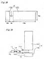
- Fig. 18 is a plan view which illustrates a flat-plane-shaped dipole antenna apparatus 16 according to a second preferred embodiment of the present invention.
- Fig. 19 is a circuit diagram which illustrates a feeder circuit for feeding electric power to the flat-plane-shaped dipole antenna apparatus 16 shown in Fig. 18 .
- the second preferred embodiment is characterized by measuring the SAR distribution using the flat-plane-shaped dipole antenna apparatus 16 instead of the minute dipole array antenna 1A according to the first preferred embodiment.
- the flat-plane-shaped dipole antenna apparatus 16 is made of, for example, a copper plate having a thickness of 0.5 mm.
- the second preferred embodiment is intended to be able to form a uniform magnetic field distribution or a substantially magnetic field distribution within a measurement range of the portable radio communication apparatus.
- the size of the flat-plane-shaped dipole antenna apparatus 16 is set to be larger than the size of an ordinary portable radio communication apparatus (a length of about 180 mm and a width of about 50 mm), i.e., the flat-plane-shaped dipole antenna apparatus 16 has a length of 200 mm and a width of 70 mm.
- the antenna is formed laterally asymmetric, and the antenna includes two rectangular radiation conductors 16A and 16B.
- the flat-plane-shaped dipole antenna apparatus 16 includes the first rectangular radiation conductor 16A having a length of 170 mm and a width of 70 mm, and the second rectangular radiation conductor 16B having a length of 30 mm and a width of 70 mm.
- the apparatus 16 is disposed at a position at which a feeding point (from the radio signal generator 2) does not fall within the actual SAR measurement range (i.e., the measurement range of the near magnetic field).
- the antenna apparatus 16 has a shape of flat plane, and is laterally asymmetric. Due to this, impedance mismatching may be caused between a feeding line and the antenna apparatus 16. In order to prevent the impedance mismatching, therefore, an impedance matching circuit 50 including a balancer 17 having a ratio of the number-of-turns of 1:4, a capacitor 18, and inductors 19-1 and 19-2 is inserted in front of the flat-plane-shaped dipole antenna apparatus 16.
- the capacitance of the capacitor 18 is set to 2.5 [pF] and the inductances of the inductors 19-1 and 19-2 are both set to 10 [nH].
- Fig. 20 is a graph which illustrates a near magnetic field distribution of the flat-plane-shaped dipole antenna apparatus 16 shown in Fig. 18 .
- the near magnetic field distribution is shown at the frequency of 900 MHz, and contour lines of the magnetic field intensity are drawn at intervals of 50 [mA/m] in a range of 0 to 700 [mA/m].
- the measurement of the near magnetic field distribution is conducted at the measurement interval "h" of 6 [mm] from the surface of the antenna, and the input electric power is set to 20 [dBm].
- the magnetic field intensity difference is about 50 to 100 [mA/m] in the ranges of -50 [mm] ⁇ x ⁇ 90 [mm] and - 25 [mm] ⁇ y ⁇ 25 [mm].
- the near magnetic field distribution is substantially uniform.
- the width of the ordinary portable radio communication apparatus is about 50 [mm], and falls within the range of -25 [mm] ⁇ y ⁇ 25 [mm].
- the magnetic field intensity near the feed point is quite high in the x direction. However, this area is out of the SAR measurement range, it is not considered to generate any error due to this high magnetic field intensity.
- An SAR measuring method using the antenna apparatus 16 according to the second preferred embodiment can be conducted in a manner similar to that of the first preferred embodiment. Even if this antenna apparatus 16 is used, a part having a low magnetic field distribution can not be caused. It is, therefore, possible to estimate or measure the SAR distribution with higher precision.
- a support base that supports a lower portion of the flat-plane-shaped dipole antenna apparatus 16 may be provided.
- the support base may be made of resin or wood.
- polytetrafluoroethylene resin or acrylic resin may be used. In this case, it is possible to decrease the influence of the dielectric substrate 3 or 15 on the electromagnetic field generated by the minute dipole antennas 1, and to measure the magnetic field and the SAR with higher precision.
- the minute dipole antennas are employed.
- the present invention is not limited to this.
- the other minute antennas such as minute loop antennas or minute slot antennas may be employed.
- the near magnetic field distribution and the SAR distribution are measured using as the reference antenna, the minute array antenna including a plurality of minute antennas or the flat-plane-shaped dipole antenna, and then, the magnetic field distribution of the portable radio communication apparatus is measured in free space. It is thereby possible to estimate or measure the SAR distribution by a quite simpler method with higher precision, as compared with the prior art.
Landscapes
- Physics & Mathematics (AREA)
- Electromagnetism (AREA)
- General Physics & Mathematics (AREA)
- Variable-Direction Aerials And Aerial Arrays (AREA)
Claims (12)
- Appareil de mesure d'un taux d'absorption spécifique SAR d'un appareil de radiocommunication, comprenant :un premier moyen de mesure (4, 4A, 4S) conçu pour mesurer dans un espace libre une première distribution de champ magnétique proche d'une onde radio irradiée depuis une antenne réseau (1-1 à 1-9) d'une antenne de référence comprenant plusieurs antennes minuscules;un deuxième moyen de mesure (7, 7A, 7S) conçu pour mesurer une distribution de taux d'absorption spécifique SAR par rapport à l'onde radio irradiée depuis ladite antenne réseau (1-1, 1-9) avec un fantôme (5) prédéterminé en utilisant un procédé de mesure prédéterminé;un premier moyen de calcul (20) conçu pour calculer une distribution de coefficient de transformation α en divisant ladite distribution de taux d'absorption spécifique SAR mesuré par un carré de ladite première distribution de champ magnétique proche mesurée ;un troisième moyen de mesure (4, 4A, 4S) conçu pour mesurer dans un espace libre une deuxième distribution de champ magnétique proche d'une onde radio irradiée depuis un appareil de radio communication (10) à mesurer ; etun deuxième moyen de calcul (20) conçu pour estimer et calculer une distribution de taux d'absorption spécifique SAR par rapport à l'onde radio irradiée depuis ledit appareil de radio communication à mesurer, en multipliant un carré de ladite deuxième distribution de champ magnétique proche mesurée par ladite distribution calculée du coefficient de transformation α.
- Appareil selon la revendication 1, dans lequel
lesdites antennes minuscules sont des antennes dipôles minuscules. - Appareil selon la revendication 1 ou 2, dans lequel
ladite antenne réseau est formée en agençant plusieurs antennes minuscules dans un réseau unimensionnel sur un plan le long d'une forme d'une surface latérale d'une tête d'un corps humain. - Appareil selon la revendication 1 ou 2, dans lequel
ladite antenne réseau est formée en agençant plusieurs antennes minuscules dans un réseau bidimensionnel sur un plan le long d'une forme d'une surface latérale d'une tête d'un corps humain. - Appareil selon l'une quelconque des revendications 1 à 4, dans lequel
ladite antenne réseau est formée en agençant plusieurs antennes minuscules à un intervalle identique "d" entre antennes. - Appareil selon la revendication 5, dans lequel
la pluralité d'antennes minuscules sont agencées dans ladite antenne réseau de sorte que l'intervalle "d" d'antenne remplit d ≤ 1,1h lorsqu'un intervalle de mesure entre ladite antenne réseau et ledit premier moyen de mesure est "h". - Appareil selon la revendication 5, dans lequel
la pluralité d'antennes minuscules sont agencées dans ladite antenne réseau de sorte que l'intervalle "d" d'antenne remplit d ≤ 1,3 h lorsqu'un intervalle de mesure entre ladite antenne réseau et ledit premier moyen de mesure est "h". - Appareil selon l'une quelconque des revendications 1 à 7, dans lequel
ladite antenne réseau est agencée de sorte que des faisceaux principaux provenant de la pluralité d'antennes minuscules soient parallèles les uns aux autres. - Appareil selon l'une quelconque des revendications 1 à 7, dans lequel
ladite antenne réseau est agencée de sorte que des faisceaux principaux provenant des antennes minuscules adjacentes les unes aux autres parmi la pluralité des antennes minuscules soient orthogonaux les uns aux autres. - Appareil de mesure d'un taux d'absorption spécifique SAR d'un appareil de radio communication, comprenant :un premier moyen de mesure (4, 4A, 4S) conçu pour mesurer dans un espace libre une première distribution de champ magnétique proche d'une onde radio irradiée depuis une antenne dipôle (16) en forme de plan plat d'une antenne de référence ;un deuxième moyen de mesure (7, 7A, 7S) conçu pour mesurer une distribution de taux d'absorption spécifique SAR par rapport à l'onde radio irradiée depuis ladite antenne dipôle en forme de plan plat, avec un fantôme prédéterminé en utilisant un procédé de mesure prédéterminé ;un premier moyen de calcul (20) conçu pour calculer une distribution de coefficient de transformation α en divisant ladite distribution de taux d'absorption spécifique SAR mesuré par un carré de ladite première distribution de champ magnétique proche mesurée ;un troisième moyen de mesure (4, 4A, 4S) conçu pour mesurer dans un espace libre une deuxième distribution de champ magnétique proche d'une onde radio irradiée depuis un appareil de radio communication (10) à mesurer ; etun deuxième moyen de calcul (20) conçu pour estimer et calculer une distribution de taux d'absorption spécifique SAR par rapport à l'onde radio irradiée depuis ledit appareil de radio communication à mesurer, en multipliant un carré de ladite deuxième distribution de champ magnétique proche mesurée par ladite distribution calculée du coefficient de transformation α.
- Appareil selon la revendication 10, dans lequel
ladite antenne dipôle en forme de plan plat comprend deux conducteurs d'irradiation rectangulaires ayant des tailles différentes à former de sorte qu'un point d'alimentation soit exclu d'une gamme d'une mesure d'un champ magnétique proche. - Appareil selon la revendication 11, comprenant en plus un circuit d'adaptation d'impédance relié à ladite antenne dipôle en forme de plan plat, ledit circuit d'adaptation d'impédance effectuant une adaptation d'impédance entre une ligne d'alimentation et l'antenne dipôle en forme de plan plat.
Applications Claiming Priority (2)
| Application Number | Priority Date | Filing Date | Title |
|---|---|---|---|
| JP2003048913 | 2003-02-26 | ||
| JP2003048913 | 2003-02-26 |
Publications (2)
| Publication Number | Publication Date |
|---|---|
| EP1452880A1 EP1452880A1 (fr) | 2004-09-01 |
| EP1452880B1 true EP1452880B1 (fr) | 2009-04-01 |
Family
ID=32767758
Family Applications (1)
| Application Number | Title | Priority Date | Filing Date |
|---|---|---|---|
| EP04004310A Expired - Lifetime EP1452880B1 (fr) | 2003-02-26 | 2004-02-26 | Appareil de mesure du taux spécifique d'absorption d'un appareil de radiocommunication |
Country Status (4)
| Country | Link |
|---|---|
| US (1) | US7268564B2 (fr) |
| EP (1) | EP1452880B1 (fr) |
| CN (1) | CN100365420C (fr) |
| DE (1) | DE602004020291D1 (fr) |
Families Citing this family (29)
| Publication number | Priority date | Publication date | Assignee | Title |
|---|---|---|---|---|
| KR20060030956A (ko) * | 2004-10-07 | 2006-04-12 | 엘지전자 주식회사 | 이동통신 단말기의 전자파 흡수율 표시방법 |
| JP2006132970A (ja) * | 2004-11-02 | 2006-05-25 | Ntt Docomo Inc | 比吸収率測定システム及び方法 |
| US7642973B2 (en) * | 2004-12-22 | 2010-01-05 | Panasonic Corporation | Electromagnetic wave analysis apparatus and design support apparatus |
| US8502546B2 (en) * | 2006-04-05 | 2013-08-06 | Emscan Corporation | Multichannel absorberless near field measurement system |
| JP5669337B2 (ja) * | 2006-10-23 | 2015-02-12 | 株式会社Nttドコモ | 比吸収率を測定するためのシステム及び方法 |
| WO2008051125A1 (fr) * | 2006-10-27 | 2008-05-02 | Telefonaktiebolaget Lm Ericsson (Publ) | Mesure d'absorption rapide |
| CN101038313B (zh) * | 2007-04-05 | 2011-04-06 | 中兴通讯股份有限公司 | 一种mat中rartut比吸收率的测量方法 |
| JP4433097B2 (ja) * | 2007-04-27 | 2010-03-17 | 株式会社村田製作所 | 無線icデバイス |
| FR2929710B1 (fr) * | 2008-04-08 | 2011-03-25 | Ecole Superieure Electricite | Procede et dispositif de mesure de debit d'absorption specifique de rayonnement electromagnetique |
| KR101049789B1 (ko) * | 2008-12-31 | 2011-07-19 | 충남대학교산학협력단 | 전자파흡수율 측정방법 |
| EP2405259B1 (fr) * | 2009-03-03 | 2019-03-13 | NTT DoCoMo, Inc. | Procédé de mesure de puissance absorbée, procédé de mesure de puissance absorbée moyenne locale, dispositif de calcul de puissance absorbée moyenne locale et programme de calcul de puissance absorbée moyenne locale |
| US8274386B1 (en) * | 2009-03-23 | 2012-09-25 | The United States Of America As Represented By The Secretary Of The Navy | Human presence electric field sensor |
| US8810460B2 (en) * | 2009-11-05 | 2014-08-19 | Atc Logistics & Electronics, Inc. | Multidimensional RF test fixture and method for securing a wireless device for RF testing |
| FR2954829B1 (fr) * | 2009-12-31 | 2012-03-02 | Art Fi | Systeme pour mesurer un champ electromagnetique |
| TW201228104A (en) * | 2010-12-16 | 2012-07-01 | Quanta Comp Inc | Method to reduce specific absorption rate of electronic device and electronic device with low specific absorption rate |
| TWI540322B (zh) * | 2012-09-08 | 2016-07-01 | 西凱渥資訊處理科技公司 | 關於近場電磁探針及掃描器之系統,裝置及方法 |
| CN103675476B (zh) * | 2012-09-17 | 2016-10-05 | 联想(北京)有限公司 | 信息处理方法及电子设备 |
| CN103823121A (zh) * | 2013-07-05 | 2014-05-28 | 广东省通讯终端产品质量监督检验中心 | 一种sar快速测试方法 |
| US9973232B1 (en) * | 2014-06-06 | 2018-05-15 | Amazon Technologies, Inc. | Low specific absorption rate (SAR) dual-band antenna structure |
| KR102219884B1 (ko) * | 2014-07-02 | 2021-02-24 | 삼성전자주식회사 | 자기장을 이용한 고유 식별자를 수신받는 사용자 단말 장치, 방법 및 위치 추적 시스템 |
| USRE49217E1 (en) * | 2014-08-21 | 2022-09-20 | Jd Design Enterprises Llc | Monitoring system for a distributed antenna system |
| US9612296B2 (en) * | 2014-10-08 | 2017-04-04 | Qualcomm Incorporated | Methods and apparatus for testing of wireless power transmitters and systems |
| FR3039282B1 (fr) * | 2015-07-24 | 2020-12-25 | Univ Rennes | Dispositif pour la dosimetrie electromagnetique et methode associee |
| JP6059837B1 (ja) * | 2016-03-22 | 2017-01-11 | 日本電信電話株式会社 | アンテナ制御装置、アンテナ制御プログラムおよびアンテナ制御システム |
| WO2019140225A1 (fr) | 2018-01-12 | 2019-07-18 | University Of Notre Dame Du Lac | Procédés et appareil de détermination de la conformité en termes d'exposition aux ondes électromagnétiques de dispositifs à antennes multiples |
| CN109856463B (zh) * | 2019-02-27 | 2021-07-27 | Oppo广东移动通信有限公司 | 测试设备 |
| CN110308333A (zh) * | 2019-08-12 | 2019-10-08 | 广东电网有限责任公司 | 一种接地网降阻效果测试装置及方法 |
| CN113675597B (zh) * | 2021-08-11 | 2023-02-28 | 中国电波传播研究所(中国电子科技集团公司第二十二研究所) | 一种附加匹配网络结构参数确定方法 |
| EP4170359B1 (fr) * | 2021-10-22 | 2024-11-06 | Université de Rennes | Dispositif d'évaluation d'exposition électromagnétique comprenant un élément d'amplification de champ |
Family Cites Families (12)
| Publication number | Priority date | Publication date | Assignee | Title |
|---|---|---|---|---|
| JP2790103B2 (ja) | 1995-12-15 | 1998-08-27 | 日本電気株式会社 | 比吸収率測定装置及び比吸収率測定方法 |
| JP2000082333A (ja) | 1998-07-10 | 2000-03-21 | Murata Mfg Co Ltd | 複合誘電体、およびそれを用いた固体生体ファントム、ならびに固体生体ファントムの製造方法。 |
| JP2002526949A (ja) * | 1998-07-14 | 2002-08-20 | ドイッチェ テレコム アーゲー | 比吸収率を測定するための装置 |
| JP3147100B2 (ja) * | 1998-09-18 | 2001-03-19 | 日本電気株式会社 | Sar測定センサ及びsar測定装置 |
| US6525657B1 (en) * | 2000-04-25 | 2003-02-25 | Aprel, Inc. | Apparatus and method for production testing of the RF performance of wireless communications devices |
| JP2002107396A (ja) | 2000-09-29 | 2002-04-10 | Matsushita Electric Ind Co Ltd | 疑似人体とそれを用いた測定方法 |
| US6603440B2 (en) * | 2000-12-14 | 2003-08-05 | Protura Wireless, Inc. | Arrayed-segment loop antenna |
| FR2827963B1 (fr) * | 2001-07-30 | 2003-10-24 | Bouygues Telecom Sa | Dispositif pour la mesure de debits d'absorption specifique sur un corps fantome qui simule un corps humain et qui est soumis a un champ electromagnetique |
| CN1300573C (zh) * | 2002-04-22 | 2007-02-14 | 松下电器产业株式会社 | 用于无线装置的相对吸收率测定装置 |
| FR2851823B1 (fr) * | 2003-02-27 | 2005-09-02 | Ecole Superieure Electricite | Procede et systeme pour mesurer un debit d'absorption specifique das |
| FR2859064B1 (fr) * | 2003-08-18 | 2005-12-30 | Satimo Sa | Dispositif de controle du debit d'absorption specifique d'objets rayonnants fabriques en serie et notamment de telephones portables |
| JP5554463B2 (ja) * | 2004-07-05 | 2014-07-23 | 株式会社Nttドコモ | 比吸収率測定装置 |
-
2004
- 2004-02-24 CN CNB2004100068265A patent/CN100365420C/zh not_active Expired - Fee Related
- 2004-02-25 US US10/784,928 patent/US7268564B2/en not_active Expired - Lifetime
- 2004-02-26 EP EP04004310A patent/EP1452880B1/fr not_active Expired - Lifetime
- 2004-02-26 DE DE602004020291T patent/DE602004020291D1/de not_active Expired - Lifetime
Also Published As
| Publication number | Publication date |
|---|---|
| US7268564B2 (en) | 2007-09-11 |
| CN1525180A (zh) | 2004-09-01 |
| DE602004020291D1 (de) | 2009-05-14 |
| US20040232776A1 (en) | 2004-11-25 |
| CN100365420C (zh) | 2008-01-30 |
| EP1452880A1 (fr) | 2004-09-01 |
Similar Documents
| Publication | Publication Date | Title |
|---|---|---|
| EP1452880B1 (fr) | Appareil de mesure du taux spécifique d'absorption d'un appareil de radiocommunication | |
| CN101170368B (zh) | 吸收率测量系统和方法 | |
| US6919845B2 (en) | Apparatus for measuring specific absorption rate based on near magnetic field for use in radio apparatus | |
| JP2737661B2 (ja) | Sar測定方法およびsar測定装置 | |
| CN1618023A (zh) | 用于测量复杂电磁场的天线阵列 | |
| JPH0560815A (ja) | 場の強さの測定装置 | |
| CN115184927B (zh) | 一种微波无损成像目标检测方法 | |
| CN100478692C (zh) | 确定辐射装置的场辐射水平的方法 | |
| Chen et al. | Analysis of log periodic dipole array antennas for site validation and radiated emissions testing | |
| JP2020034285A (ja) | 磁界空間分布検出装置 | |
| JP4471583B2 (ja) | Sar測定装置 | |
| Fourestie et al. | Spherical near field facility for characterizing random emissions | |
| JP3593566B2 (ja) | アンテナ測定方法及びアンテナ測定装置 | |
| JP2004279411A (ja) | 無線通信装置用比吸収率測定装置 | |
| JP2003332999A (ja) | 局所sar測定装置及び方法 | |
| JP3436669B2 (ja) | 電磁波結合装置 | |
| JP7410561B2 (ja) | 電波センサ、および電界成分検出装置 | |
| Alexander et al. | The design of dipole and monopole antennas with low uncertainties | |
| CN209803768U (zh) | 基于表面电磁波的柔性触控屏和柔性触控装置 | |
| Criel et al. | Theoretical and experimental quantitative characterization of the near-fields of printed circuit board interconnection structures | |
| JP2011017535A (ja) | 遠方電磁界ノイズ測定方法および装置 | |
| US7721347B2 (en) | Scanning nanotube probe device and associated method | |
| Krogerus et al. | Evaluation of three methods for measuring total radiated power of handset antennas | |
| Bozdağ et al. | Spatial filtering in planar near field antenna measurement system and comparison of two gain calculation approaches | |
| Alexander et al. | CISPR standard for calibration of EMC antennas |
Legal Events
| Date | Code | Title | Description |
|---|---|---|---|
| PUAI | Public reference made under article 153(3) epc to a published international application that has entered the european phase |
Free format text: ORIGINAL CODE: 0009012 |
|
| AK | Designated contracting states |
Kind code of ref document: A1 Designated state(s): AT BE BG CH CY CZ DE DK EE ES FI FR GB GR HU IE IT LI LU MC NL PT RO SE SI SK TR |
|
| AX | Request for extension of the european patent |
Extension state: AL LT LV MK |
|
| 17P | Request for examination filed |
Effective date: 20040902 |
|
| AKX | Designation fees paid |
Designated state(s): DE FR GB |
|
| RBV | Designated contracting states (corrected) |
Designated state(s): DE FR GB |
|
| GRAP | Despatch of communication of intention to grant a patent |
Free format text: ORIGINAL CODE: EPIDOSNIGR1 |
|
| RAP1 | Party data changed (applicant data changed or rights of an application transferred) |
Owner name: PANASONIC CORPORATION |
|
| GRAS | Grant fee paid |
Free format text: ORIGINAL CODE: EPIDOSNIGR3 |
|
| RIN1 | Information on inventor provided before grant (corrected) |
Inventor name: KAJIWARA, SHOICHI Inventor name: ASAYAMA, YOSHITAKA Inventor name: OZAKI, AKIHIRO Inventor name: OGAWA, KOICHI Inventor name: YAMAMOTO, ATSUSHI Inventor name: KOYANAGI, YOSHIO Inventor name: SAITO, YUTAKA |
|
| GRAA | (expected) grant |
Free format text: ORIGINAL CODE: 0009210 |
|
| AK | Designated contracting states |
Kind code of ref document: B1 Designated state(s): DE FR GB |
|
| REG | Reference to a national code |
Ref country code: GB Ref legal event code: FG4D |
|
| REF | Corresponds to: |
Ref document number: 602004020291 Country of ref document: DE Date of ref document: 20090514 Kind code of ref document: P |
|
| PLBE | No opposition filed within time limit |
Free format text: ORIGINAL CODE: 0009261 |
|
| STAA | Information on the status of an ep patent application or granted ep patent |
Free format text: STATUS: NO OPPOSITION FILED WITHIN TIME LIMIT |
|
| 26N | No opposition filed |
Effective date: 20100105 |
|
| PGFP | Annual fee paid to national office [announced via postgrant information from national office to epo] |
Ref country code: FR Payment date: 20120221 Year of fee payment: 9 |
|
| PGFP | Annual fee paid to national office [announced via postgrant information from national office to epo] |
Ref country code: DE Payment date: 20120222 Year of fee payment: 9 |
|
| PGFP | Annual fee paid to national office [announced via postgrant information from national office to epo] |
Ref country code: GB Payment date: 20120222 Year of fee payment: 9 |
|
| GBPC | Gb: european patent ceased through non-payment of renewal fee |
Effective date: 20130226 |
|
| REG | Reference to a national code |
Ref country code: FR Ref legal event code: ST Effective date: 20131031 |
|
| REG | Reference to a national code |
Ref country code: DE Ref legal event code: R119 Ref document number: 602004020291 Country of ref document: DE Effective date: 20130903 |
|
| PG25 | Lapsed in a contracting state [announced via postgrant information from national office to epo] |
Ref country code: GB Free format text: LAPSE BECAUSE OF NON-PAYMENT OF DUE FEES Effective date: 20130226 Ref country code: FR Free format text: LAPSE BECAUSE OF NON-PAYMENT OF DUE FEES Effective date: 20130228 Ref country code: DE Free format text: LAPSE BECAUSE OF NON-PAYMENT OF DUE FEES Effective date: 20130903 |
|
| P01 | Opt-out of the competence of the unified patent court (upc) registered |
Effective date: 20230522 |