EP1452884A1 - Supraleitfähiger Magnetapparat und Apparat der Kerspintomographie - Google Patents
Supraleitfähiger Magnetapparat und Apparat der Kerspintomographie Download PDFInfo
- Publication number
- EP1452884A1 EP1452884A1 EP04250936A EP04250936A EP1452884A1 EP 1452884 A1 EP1452884 A1 EP 1452884A1 EP 04250936 A EP04250936 A EP 04250936A EP 04250936 A EP04250936 A EP 04250936A EP 1452884 A1 EP1452884 A1 EP 1452884A1
- Authority
- EP
- European Patent Office
- Prior art keywords
- cryo
- compressor
- disposed
- superconductive
- coils
- Prior art date
- Legal status (The legal status is an assumption and is not a legal conclusion. Google has not performed a legal analysis and makes no representation as to the accuracy of the status listed.)
- Withdrawn
Links
- 238000002595 magnetic resonance imaging Methods 0.000 title claims description 18
- 239000002826 coolant Substances 0.000 claims description 21
- 238000001816 cooling Methods 0.000 claims description 12
- 239000002887 superconductor Substances 0.000 claims description 8
- 238000005481 NMR spectroscopy Methods 0.000 claims 1
- 235000012489 doughnuts Nutrition 0.000 abstract 1
- 239000007789 gas Substances 0.000 description 8
- 239000001307 helium Substances 0.000 description 7
- 229910052734 helium Inorganic materials 0.000 description 7
- SWQJXJOGLNCZEY-UHFFFAOYSA-N helium atom Chemical compound [He] SWQJXJOGLNCZEY-UHFFFAOYSA-N 0.000 description 7
- 238000012423 maintenance Methods 0.000 description 5
- 241001465754 Metazoa Species 0.000 description 2
- 239000004020 conductor Substances 0.000 description 2
- 238000010276 construction Methods 0.000 description 2
- 229910052738 indium Inorganic materials 0.000 description 2
- APFVFJFRJDLVQX-UHFFFAOYSA-N indium atom Chemical compound [In] APFVFJFRJDLVQX-UHFFFAOYSA-N 0.000 description 2
- RYGMFSIKBFXOCR-UHFFFAOYSA-N Copper Chemical compound [Cu] RYGMFSIKBFXOCR-UHFFFAOYSA-N 0.000 description 1
- 229910052782 aluminium Inorganic materials 0.000 description 1
- XAGFODPZIPBFFR-UHFFFAOYSA-N aluminium Chemical compound [Al] XAGFODPZIPBFFR-UHFFFAOYSA-N 0.000 description 1
- 229910052802 copper Inorganic materials 0.000 description 1
- 239000010949 copper Substances 0.000 description 1
- 239000000835 fiber Substances 0.000 description 1
- 238000007710 freezing Methods 0.000 description 1
- 230000008014 freezing Effects 0.000 description 1
- 239000011796 hollow space material Substances 0.000 description 1
- 239000007788 liquid Substances 0.000 description 1
- 239000000463 material Substances 0.000 description 1
- 238000005259 measurement Methods 0.000 description 1
- 238000005057 refrigeration Methods 0.000 description 1
- 238000007789 sealing Methods 0.000 description 1
- 238000003325 tomography Methods 0.000 description 1
Images



Classifications
-
- G—PHYSICS
- G01—MEASURING; TESTING
- G01R—MEASURING ELECTRIC VARIABLES; MEASURING MAGNETIC VARIABLES
- G01R33/00—Arrangements or instruments for measuring magnetic variables
- G01R33/20—Arrangements or instruments for measuring magnetic variables involving magnetic resonance
- G01R33/28—Details of apparatus provided for in groups G01R33/44 - G01R33/64
- G01R33/38—Systems for generation, homogenisation or stabilisation of the main or gradient magnetic field
- G01R33/381—Systems for generation, homogenisation or stabilisation of the main or gradient magnetic field using electromagnets
- G01R33/3815—Systems for generation, homogenisation or stabilisation of the main or gradient magnetic field using electromagnets with superconducting coils, e.g. power supply therefor
Definitions
- the present invention relates to a superconductive magnet apparatus and a magnetic resonance imaging apparatus (hereinafter referred to as MRI) using the magnet apparatus, and more particularly to a superconductive magnet apparatus and a MRI apparatus using the same that does not give feeling of blockade to human bodies to be examined or inspected.
- MRI magnetic resonance imaging apparatus
- the superconductive magnet apparatus disclosed in the reference 1 is a cylindrical and a horizontal magnetic field type MRI apparatus, wherein a cryostat has a central hollow in which a cryo-compressor is disposed.
- the cryostat is constituted by a housing or a vacuum vessel covering the magnet.
- an apparatus disclosed in Japanese Patent Laid-open Hei 11-16718 (hereinafter referred to as reference 2) has a cryo-compressor for cooling a cooling medium, the cryo-compressor being placed on a vacuum vessel.
- the superconductive magnet apparatus disclosed in the reference 1 is not an apparatus of a vertical magnet field system that is the subject of the present invention.
- the apparatus of the reference 1 is a cylindrical type of a horizontal magnetic field, which is different from the apparatus of the present invention in application direction of magnetic field, and an arrangement construction of superconductors, etc.
- the reference 1 does not disclose the arrangement of the cryo-compressor for the vertical magnetic field system that is the subject of the present invention.
- the superconductive magnet apparatus disclosed in the reference 2 is concerned with the vertical magnetic field system, wherein the cryo-compressor for cooling the cooling medium is placed on the vacuum vessel so that the superconductive magnet apparatus becomes large in its height as a whole.
- the present invention aims at solving the above-mentioned problem, and an object of the present invention is to provide a superconductive magnet apparatus and a MRI apparatus that exhibit a sufficiently high refrigeration performance and are small in their overall sizes.
- the present invention is featured in that the superconductive magnet and the cryo-compressor disposed in superconductive coils that cools the cooling medium is placed in a concave formed at a position where an experience magnetic field is weak.
- experience magnetic field mean a magnetic field strength at a position where a magnetic object is placed; i.e. the magnetic strength felt by the coil, the cooling medium, etc.
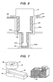
- the MRI apparatus comprises, as shown in Fig. 7, superconductors (not shown), coil containers (not shown) for accommodating the coils and a cooling medium, vacuum vessels 41, 42 covering the coil containers and being evacuated to be vacuum, a superconductive magnet 80 comprising the cryo-compressor 51 for cooling the cooling medium, a bed or table 90 for supporting a human body or other bodies to be inspected or examined, and a controller 100 for analyzing signals from the body, wherein the vacuum vessels 41, 42 are so disposed as to face each other and to form a vertical magnetic field therebetween, so that the tomography of the body on the bed or table is carried out.
- the coil containers 21, 22 function as tanks or containers for accommodating the cooling medium.
- thermal shields 31, 32 for covering the coil containers 21, 22; and a cryostat 5 comprising the vacuum vessels 41, 42 covers the thermal shields 31, 32 to keep the cold of the cooling medium.
- the cryostat is constituted by the vacuum vessels 41, 42, He container21, 22, etc.
- the concave 1 is formed at the upper portion of the cryostat.
- the vacuum vessels are communicated with each other via a passage 61.
- a lateral or horizontal bore or hollow space 2 is formed in the center of the cryostat 5.
- a human body or other bodies to be examined or inspected is placed in the bore 2.
- a magnetic field space is formed in the bore 2 or space 2 between the coil containers.
- the magnetic field center is located at the center of the bore between the magnets.
- the cryo-compressor 51 for cooling the cooling medium 4 is disposed via a cryo-compressor port 158 in the cylindrical or square concave 1 formed at the center of the cryostat, the cryo-compressor being disposed along the vertical direction.
- the upper and lower coil containers 21, 22 are communicated with each other via a connecting passage 61 through which the cooling medium passes.
- the cryo-compressor 51 When the cryo-compressor 51 is disposed along the vertical direction, the cooling medium 4 filled therein is cooled effectively, so that the efficiency of the cryo-compressor becomes high.
- cryo-compressor the cold heads
- the coil container 21 there is formed an appropriate opening in the cryostat 5, and a cooling stage of cryo-compressor (the cold heads) at the lower temperature side is disposed in the coil container 21 so as to cool directly liquid helium.
- An embodiment of the cryo-compressor will be explained later.
- the cryo-compressor 51 is placed vertically in the concave 1 formed in the center of the cryostat. Further, when a lid is fitted to the concave where the cryo-compressor is placed, noise generated from the cryo-compressor 51 is isolated to make the apparatus silent.
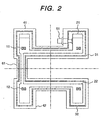
- the second embodiment of the present invention is shown in Fig. 2.
- the cryo-compressor 51 that is disposed in the vertical direction in the embodiment 1 is placed in the lateral direction.
- the height of the cryostat 5 becomes lower than that of the first embodiment so that the MRI apparatus can be made more compact than the first embodiment.
- the third embodiment is shown in Fig. 3.
- a superconductive magnet apparatus wherein a superconductive shield coils 13, 14 for active shielding are added to the embodiment 1, the cryo-compressor 51 being disposed in the central axis of the magnet.
- the shield coils 13, 14 circular superconductors, as same as the superconductive coils, and electric current flowing through the shield coils 13 and current flowing through the shield coil 14 flow in opposite directions.
- the current flowing through the superconductive coil 11 and the shield coil 14 flows the same direction. Accordingly, the shield coils 13, 14 can shield magnetic force generated from the superconductive coils 11, 12 so that a magnetic field formed outer peripheries of the superconductive coils 11, 12 is not so strong.
- the cryo-compressor 51 can be disposed at a position where the strength of experience magnetic field is weak, so that the performance and reliability of the cryo-compressor 51 can be improved.
- the cooling medium (especially at the lower temperature stage side) filled in the cryo-compressor 51 lowers its refrigerating efficiency due to worse thermal transferring efficiency if the experience magnetic field is strong.
- the cooling efficiency of the cryo-compressor can be increased.
- the fourth embodiment of the present invention is shown in Fig. 4.
- the cryo-compressor 51 is disposed in the diagonal direction near the shield coils 13, 14, which are employed in the third embodiment. That is, when the center of the magnetic field space is the crossing point of the dashed lines, and the shield coil 13 is designated, the head of the cryo-compressor is located on the line connecting the center and the shield coil 13.
- the cryo-compressor 51 can be disposed at a position located between the superconductor 11 and the shield cols 13, 14 where the experience magnetic field is weak, performance and efficiency of the cryo-compressor 51 will be improved, and the height of the cryostat can be shortened to make the MRI apparatus compact.
- cryo-compressor 51 when the cryo-compressor 51 is pulled out at the time of maintenance, it is necessary to pull out the cryo-compressor 51 along the direction where the lower temperature stage side (cold head) extends. In this embodiment of the present invention where the cryo-compressor 51 is disposed in the diagonal direction, the cryo-compressor 51 can be pulled out without forming a wide space in the portion above the cryostat; thus the maintenance of the apparatus is easy.
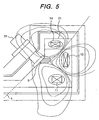
- Fig. 5 shows the magnetic state around the cryo-compressor 51 employed in the embodiment shown in Fig. 4.
- the cryo-compressor 51 is disposed at a position located between the superconductive coils 11, 12 and the shield coils 13, 14 where the strength of the experience magnetic field is weak, and on the path connecting the center 8 of the magnetic space formed by the superconductive coils 11, 12 and the shield coils 13, 14.
- the position where the strength of the experience magnetic field is weak is formed in the direction extending of the cryo-compressor 51 by the shield coils 13, 14 for forming active shield.
- the efficiency of the cryo-compressor is lowered; however, in the present invention, the MRI apparatus can be operated, keeping a high efficiency of the cryo-compressor, since the cooling medium of the cryo-compressor is placed at a position where the strength of the experience magnetic field is weak.
- Fig. 6 shows a sectional view of an example of the structure of the cryo-compressor 51, which is a Gifford-McMahon (GM) type cryo-compressor.
- a high heat conductive, flexible member 150 is disposed at a part between a cryo-compressor head 158a and a cryo-compressor port 158 so as to transfer cooling heat from the cryo-compressor head to the low temperature side 158a and the middle temperature side 158b of the cryo-compressor port 158.
- the lower temperature side and the higher temperature side and lower temperature 158a can always contact with the middle temperature side 158b of the cryo-compressor port.
- the flexible member 150 high heat conductive materials such as indium, etc. are preferable. Other materials than indium, fibers of copper or aluminum, etc. can be used in a combined form, which has good flexibility, whereby thermal contact is good.
- the high thermal conductive member 150 is disposed at part between the cryo-compressor heads 157am 157b and the cryo-compressor port 158, so that the heat conductivity between the cryo-compressor head and the high temperature section 158a, the low temperature section 158b of the cryo-compressor port 158 is increased. Further, since the high thermal conductive material is flexible, the low temperature 157a, middle temperature head 157b, low temperature section 158a, high temperature section 158b of the cryo-compressor can contact each other with high efficiency.
- Helium gas 152 is filled in other part between the cryo-compressor head and the cryo-compressor port 158, gas being supplied by way of a gas supply tube 153 and a valve (not shown).
- An O-ring 154 is disposed as an air-tight sealing.
- Helium gas 152 in the cryo-compressor port 158 works to transfer cooling heat by the conductive heat of helium when the high heat conductive, flexible member 150 is peeled off from the cryo-compressor port 158 or heads 157a, 157b. The smaller the gap between the high temperature side and the low temperature side is, the conductive heat becomes larger. In this case, the gap is as small as about 100 micrometers or less.
- the cooling heat is transferred to the shield 31 without problem.
- air does not enter the inside from the cryo-compressor port 158 to prevent freezing, while opening the valve and supplying helium gas from a gas bomb (not shown) into the gap between the cryo-compressor 51 and the cryo-compressor port 158.
- cryo-compressor 51 As soon as the cryo-compressor 51 is pulled out from the cryo-compressor port 158, the upper part of the cryo-compressor port 158 is closed, so as not to prevent air from entering into the inside.
- helium gas can be filled entirely in the cryo-compressor port, while supplying helium gas 152 into the inside of the cryo-compressor 51.
- the superconductive magnet apparatus of the present invention has such a structure that the cryo-compressor is easily disposed and dismounted, and that even if the cryo-compressor is out of order, exchange of parts or the cryo-compressor with new parts or new cryo-compressor is conducted.
- the cryo-compressor is disposed in the concave formed at the center of the cryostat so that the size of the apparatus can be made small.
- the maintenance of the NMR apparatus can be easy because the height of the magnets becomes very small.
- the height of the NMR apparatus is small, human bodies or animals do not feel stress.
- the maintenance work over the magnets is easy and safer than the conventional apparatus.
- the open type NMR apparatus is used to mean that the NMR apparatus has no envelope like the conventional tunnel type NMR apparatus.
- the human body or animals feel open-system, and accessibility to the measurement region is good.
- the magnet superconductive magnet or permanent magnet
- the magnet is divided into two sections, so as to sandwich the table or bed.
- the present invention it is possible to provide a MRI apparatus with an improved performance of the cryo-compressor, because the cryo-compressor is disposed at a position where the experience magnetic field is weak.
Landscapes
- Physics & Mathematics (AREA)
- Electromagnetism (AREA)
- Condensed Matter Physics & Semiconductors (AREA)
- General Physics & Mathematics (AREA)
- Magnetic Resonance Imaging Apparatus (AREA)
Applications Claiming Priority (2)
| Application Number | Priority Date | Filing Date | Title |
|---|---|---|---|
| JP2003052246 | 2003-02-28 | ||
| JP2003052246 | 2003-02-28 |
Publications (1)
| Publication Number | Publication Date |
|---|---|
| EP1452884A1 true EP1452884A1 (de) | 2004-09-01 |
Family
ID=32767816
Family Applications (1)
| Application Number | Title | Priority Date | Filing Date |
|---|---|---|---|
| EP04250936A Withdrawn EP1452884A1 (de) | 2003-02-28 | 2004-02-20 | Supraleitfähiger Magnetapparat und Apparat der Kerspintomographie |
Country Status (2)
| Country | Link |
|---|---|
| US (1) | US7482808B2 (de) |
| EP (1) | EP1452884A1 (de) |
Families Citing this family (3)
| Publication number | Priority date | Publication date | Assignee | Title |
|---|---|---|---|---|
| US7500366B2 (en) * | 2005-12-08 | 2009-03-10 | Shi-Apd Cryogencis, Inc. | Refrigerator with magnetic shield |
| JP5942700B2 (ja) * | 2012-08-23 | 2016-06-29 | 国立大学法人京都大学 | 磁気共鳴信号検出用プローブ |
| WO2020155137A1 (en) | 2019-02-02 | 2020-08-06 | Shanghai United Imaging Healthcare Co., Ltd. | Radiation therapy system and method |
Citations (4)
| Publication number | Priority date | Publication date | Assignee | Title |
|---|---|---|---|---|
| US5361054A (en) * | 1990-03-29 | 1994-11-01 | Bruker Analytische Messtechnik Gmbh | Magnet system |
| US6396376B1 (en) * | 1999-04-23 | 2002-05-28 | General Electric Company | Apparatus and method for a superconductive magnet with pole piece |
| WO2002071942A1 (en) * | 2001-03-14 | 2002-09-19 | Hitachi Medical Corporation | Magnetic resonance imaging apparatus and static magnetic field generating apparatus used therefor |
| JP2002336216A (ja) * | 2001-03-16 | 2002-11-26 | Hitachi Medical Corp | 開放型磁気共鳴イメージング装置 |
Family Cites Families (12)
| Publication number | Priority date | Publication date | Assignee | Title |
|---|---|---|---|---|
| US5045826A (en) | 1990-04-05 | 1991-09-03 | General Electric Company | Actively shielded magnetic resonance magnet without cryogens |
| JP2821241B2 (ja) * | 1990-06-08 | 1998-11-05 | 株式会社日立製作所 | 液化冷凍機付きクライオスタツト |
| DE59609147D1 (de) * | 1995-11-16 | 2002-06-06 | Siemens Ag | Magnetanordnung für ein diagnostisches Magnetresonanzgerät |
| JP3654463B2 (ja) * | 1996-03-29 | 2005-06-02 | 株式会社日立メディコ | 磁気共鳴イメージング装置 |
| JP3537639B2 (ja) | 1997-06-26 | 2004-06-14 | 三菱電機株式会社 | 超電導電磁石装置 |
| US6011456A (en) * | 1998-12-30 | 2000-01-04 | Eckels; Phillip W. | Superconducting magnet split cryostat cryogen ride-through reserve |
| JP3577661B2 (ja) * | 1999-09-29 | 2004-10-13 | 住友重機械工業株式会社 | パルス管冷凍機 |
| JP3728167B2 (ja) * | 2000-02-10 | 2005-12-21 | 株式会社日立メディコ | 磁気共鳴イメージング装置 |
| US6438990B1 (en) * | 2000-06-12 | 2002-08-27 | Jay K. Hertling | Refrigeration system |
| JP3968211B2 (ja) * | 2000-08-31 | 2007-08-29 | 株式会社日立製作所 | 微弱磁場計測デュワー |
| US6717408B2 (en) | 2001-04-05 | 2004-04-06 | Intermagnetics General Corporation | Support structure for open MRI apparatus |
| US6807812B2 (en) * | 2003-03-19 | 2004-10-26 | Ge Medical Systems Global Technology Company, Llc | Pulse tube cryocooler system for magnetic resonance superconducting magnets |
-
2004
- 2004-02-20 EP EP04250936A patent/EP1452884A1/de not_active Withdrawn
- 2004-02-26 US US10/785,947 patent/US7482808B2/en not_active Expired - Fee Related
Patent Citations (5)
| Publication number | Priority date | Publication date | Assignee | Title |
|---|---|---|---|---|
| US5361054A (en) * | 1990-03-29 | 1994-11-01 | Bruker Analytische Messtechnik Gmbh | Magnet system |
| US6396376B1 (en) * | 1999-04-23 | 2002-05-28 | General Electric Company | Apparatus and method for a superconductive magnet with pole piece |
| WO2002071942A1 (en) * | 2001-03-14 | 2002-09-19 | Hitachi Medical Corporation | Magnetic resonance imaging apparatus and static magnetic field generating apparatus used therefor |
| EP1371328A1 (de) * | 2001-03-14 | 2003-12-17 | Hitachi Medical Corporation | Apparat für die magnetische resonanztomographie und apparat zur erzeugung eines statischen magnetfelds dafür |
| JP2002336216A (ja) * | 2001-03-16 | 2002-11-26 | Hitachi Medical Corp | 開放型磁気共鳴イメージング装置 |
Non-Patent Citations (1)
| Title |
|---|
| PATENT ABSTRACTS OF JAPAN vol. 2003, no. 03 5 May 2003 (2003-05-05) * |
Also Published As
| Publication number | Publication date |
|---|---|
| US7482808B2 (en) | 2009-01-27 |
| US20040169515A1 (en) | 2004-09-02 |
Similar Documents
| Publication | Publication Date | Title |
|---|---|---|
| EP0773565B1 (de) | Offener kryogengekühlter supraleitender Magnet für die Bilderzeugung durch magnetische Resonanz | |
| JP4138922B2 (ja) | パルスチューブ冷凍機 | |
| CN102597794B (zh) | 低温冷却超导体rf头部线圈阵列和具有超导的头部专用mri系统 | |
| CN102483449B (zh) | 用于磁共振成像的低温冷却超导体梯度线圈模块 | |
| JP3711659B2 (ja) | 開放形磁気共鳴作像磁石 | |
| CN102483447B (zh) | 包含超导主磁体、超导梯度场线圈和冷却rf线圈的mri系统 | |
| US5412363A (en) | Open access superconducting MRI magnet | |
| JP3615119B2 (ja) | 磁極片付き超伝導マグネット用の装置および方法 | |
| US20070001521A1 (en) | Device for generating a pulsed magnetic field | |
| US5568104A (en) | Open MRI superconductive magnet with cryogenic-fluid cooling | |
| WO2011060699A1 (zh) | 适用于磁共振成像的低温冷却的超导体梯度线圈模块 | |
| EP1293993A2 (de) | Supraleitende Magnetvorrichtung und Bilderzeugungsvorrichtung durch magnetische resonanz unter verwendung derselben | |
| US7482808B2 (en) | Superconductive magnet apparatus and magnetic resonance imaging apparatus | |
| US6816051B2 (en) | Superconducting magnet and magnetic resonance imaging apparatus using the same | |
| JP4065747B2 (ja) | 超電導磁石及びそれを用いた磁気共鳴イメージング装置 | |
| CN1957429B (zh) | 用于制冷机的导电屏蔽罩 | |
| US11320500B2 (en) | Cryogenic device for magnetic resonance imagery scanner and magnetic resonance imagery assembly comprising such cryogenic device | |
| JP2000041965A (ja) | 生体磁気計測装置 | |
| JP4079101B2 (ja) | 超伝導磁石装置及びそれを用いた磁気共鳴イメージング装置 | |
| JPH10321430A (ja) | 超電導電磁石装置 | |
| JPH0734294Y2 (ja) | 極低温冷却装置 | |
| JP2006095022A (ja) | 超電導磁石装置及びこれを用いた磁気共鳴イメージング装置 | |
| JP2000102520A (ja) | 磁気共鳴イメージング装置 | |
| WO2005117036A1 (en) | Electrically conductive shield for refrigerator | |
| JPH03112537A (ja) | Mri装置 |
Legal Events
| Date | Code | Title | Description |
|---|---|---|---|
| PUAI | Public reference made under article 153(3) epc to a published international application that has entered the european phase |
Free format text: ORIGINAL CODE: 0009012 |
|
| 17P | Request for examination filed |
Effective date: 20040309 |
|
| AK | Designated contracting states |
Kind code of ref document: A1 Designated state(s): AT BE BG CH CY CZ DE DK EE ES FI FR GB GR HU IE IT LI LU MC NL PT RO SE SI SK TR |
|
| AX | Request for extension of the european patent |
Extension state: AL HR LT LV MK |
|
| AKX | Designation fees paid |
Designated state(s): DE FR GB IT NL |
|
| RBV | Designated contracting states (corrected) |
Designated state(s): DE FR GB IT NL |
|
| STAA | Information on the status of an ep patent application or granted ep patent |
Free format text: STATUS: THE APPLICATION HAS BEEN WITHDRAWN |
|
| 18W | Application withdrawn |
Effective date: 20100701 |