EP1453157A2 - Laserverstärkersystem - Google Patents
Laserverstärkersystem Download PDFInfo
- Publication number
- EP1453157A2 EP1453157A2 EP04012996A EP04012996A EP1453157A2 EP 1453157 A2 EP1453157 A2 EP 1453157A2 EP 04012996 A EP04012996 A EP 04012996A EP 04012996 A EP04012996 A EP 04012996A EP 1453157 A2 EP1453157 A2 EP 1453157A2
- Authority
- EP
- European Patent Office
- Prior art keywords
- amplifier system
- laser
- laser amplifier
- solid
- cooling
- Prior art date
- Legal status (The legal status is an assumption and is not a legal conclusion. Google has not performed a legal analysis and makes no representation as to the accuracy of the status listed.)
- Granted
Links
Images


Classifications
-
- H—ELECTRICITY
- H01—ELECTRIC ELEMENTS
- H01S—DEVICES USING THE PROCESS OF LIGHT AMPLIFICATION BY STIMULATED EMISSION OF RADIATION [LASER] TO AMPLIFY OR GENERATE LIGHT; DEVICES USING STIMULATED EMISSION OF ELECTROMAGNETIC RADIATION IN WAVE RANGES OTHER THAN OPTICAL
- H01S3/00—Lasers, i.e. devices using stimulated emission of electromagnetic radiation in the infrared, visible or ultraviolet wave range
- H01S3/10—Controlling the intensity, frequency, phase, polarisation or direction of the emitted radiation, e.g. switching, gating, modulating or demodulating
- H01S3/106—Controlling the intensity, frequency, phase, polarisation or direction of the emitted radiation, e.g. switching, gating, modulating or demodulating by controlling devices placed within the cavity
- H01S3/108—Controlling the intensity, frequency, phase, polarisation or direction of the emitted radiation, e.g. switching, gating, modulating or demodulating by controlling devices placed within the cavity using non-linear optical devices, e.g. exhibiting Brillouin or Raman scattering
- H01S3/109—Frequency multiplication, e.g. harmonic generation
-
- H—ELECTRICITY
- H01—ELECTRIC ELEMENTS
- H01S—DEVICES USING THE PROCESS OF LIGHT AMPLIFICATION BY STIMULATED EMISSION OF RADIATION [LASER] TO AMPLIFY OR GENERATE LIGHT; DEVICES USING STIMULATED EMISSION OF ELECTROMAGNETIC RADIATION IN WAVE RANGES OTHER THAN OPTICAL
- H01S3/00—Lasers, i.e. devices using stimulated emission of electromagnetic radiation in the infrared, visible or ultraviolet wave range
- H01S3/02—Constructional details
- H01S3/04—Arrangements for thermal management
- H01S3/042—Arrangements for thermal management for solid state lasers
-
- H—ELECTRICITY
- H01—ELECTRIC ELEMENTS
- H01S—DEVICES USING THE PROCESS OF LIGHT AMPLIFICATION BY STIMULATED EMISSION OF RADIATION [LASER] TO AMPLIFY OR GENERATE LIGHT; DEVICES USING STIMULATED EMISSION OF ELECTROMAGNETIC RADIATION IN WAVE RANGES OTHER THAN OPTICAL
- H01S3/00—Lasers, i.e. devices using stimulated emission of electromagnetic radiation in the infrared, visible or ultraviolet wave range
- H01S3/05—Construction or shape of optical resonators; Accommodation of active medium therein; Shape of active medium
- H01S3/06—Construction or shape of active medium
- H01S3/0602—Crystal lasers or glass lasers
- H01S3/0604—Crystal lasers or glass lasers in the form of a plate or disc
-
- H—ELECTRICITY
- H01—ELECTRIC ELEMENTS
- H01S—DEVICES USING THE PROCESS OF LIGHT AMPLIFICATION BY STIMULATED EMISSION OF RADIATION [LASER] TO AMPLIFY OR GENERATE LIGHT; DEVICES USING STIMULATED EMISSION OF ELECTROMAGNETIC RADIATION IN WAVE RANGES OTHER THAN OPTICAL
- H01S3/00—Lasers, i.e. devices using stimulated emission of electromagnetic radiation in the infrared, visible or ultraviolet wave range
- H01S3/05—Construction or shape of optical resonators; Accommodation of active medium therein; Shape of active medium
- H01S3/06—Construction or shape of active medium
- H01S3/07—Construction or shape of active medium consisting of a plurality of parts, e.g. segments
-
- H—ELECTRICITY
- H01—ELECTRIC ELEMENTS
- H01S—DEVICES USING THE PROCESS OF LIGHT AMPLIFICATION BY STIMULATED EMISSION OF RADIATION [LASER] TO AMPLIFY OR GENERATE LIGHT; DEVICES USING STIMULATED EMISSION OF ELECTROMAGNETIC RADIATION IN WAVE RANGES OTHER THAN OPTICAL
- H01S3/00—Lasers, i.e. devices using stimulated emission of electromagnetic radiation in the infrared, visible or ultraviolet wave range
- H01S3/05—Construction or shape of optical resonators; Accommodation of active medium therein; Shape of active medium
- H01S3/08—Construction or shape of optical resonators or components thereof
- H01S3/081—Construction or shape of optical resonators or components thereof comprising three or more reflectors
-
- H—ELECTRICITY
- H01—ELECTRIC ELEMENTS
- H01S—DEVICES USING THE PROCESS OF LIGHT AMPLIFICATION BY STIMULATED EMISSION OF RADIATION [LASER] TO AMPLIFY OR GENERATE LIGHT; DEVICES USING STIMULATED EMISSION OF ELECTROMAGNETIC RADIATION IN WAVE RANGES OTHER THAN OPTICAL
- H01S3/00—Lasers, i.e. devices using stimulated emission of electromagnetic radiation in the infrared, visible or ultraviolet wave range
- H01S3/09—Processes or apparatus for excitation, e.g. pumping
- H01S3/091—Processes or apparatus for excitation, e.g. pumping using optical pumping
- H01S3/094—Processes or apparatus for excitation, e.g. pumping using optical pumping by coherent light
- H01S3/0941—Processes or apparatus for excitation, e.g. pumping using optical pumping by coherent light of a laser diode
-
- H—ELECTRICITY
- H01—ELECTRIC ELEMENTS
- H01S—DEVICES USING THE PROCESS OF LIGHT AMPLIFICATION BY STIMULATED EMISSION OF RADIATION [LASER] TO AMPLIFY OR GENERATE LIGHT; DEVICES USING STIMULATED EMISSION OF ELECTROMAGNETIC RADIATION IN WAVE RANGES OTHER THAN OPTICAL
- H01S3/00—Lasers, i.e. devices using stimulated emission of electromagnetic radiation in the infrared, visible or ultraviolet wave range
- H01S3/10—Controlling the intensity, frequency, phase, polarisation or direction of the emitted radiation, e.g. switching, gating, modulating or demodulating
- H01S3/106—Controlling the intensity, frequency, phase, polarisation or direction of the emitted radiation, e.g. switching, gating, modulating or demodulating by controlling devices placed within the cavity
- H01S3/1062—Controlling the intensity, frequency, phase, polarisation or direction of the emitted radiation, e.g. switching, gating, modulating or demodulating by controlling devices placed within the cavity using a controlled passive interferometer, e.g. a Fabry-Perot etalon
-
- H—ELECTRICITY
- H01—ELECTRIC ELEMENTS
- H01S—DEVICES USING THE PROCESS OF LIGHT AMPLIFICATION BY STIMULATED EMISSION OF RADIATION [LASER] TO AMPLIFY OR GENERATE LIGHT; DEVICES USING STIMULATED EMISSION OF ELECTROMAGNETIC RADIATION IN WAVE RANGES OTHER THAN OPTICAL
- H01S3/00—Lasers, i.e. devices using stimulated emission of electromagnetic radiation in the infrared, visible or ultraviolet wave range
- H01S3/02—Constructional details
- H01S3/025—Constructional details of solid state lasers, e.g. housings or mountings
-
- H—ELECTRICITY
- H01—ELECTRIC ELEMENTS
- H01S—DEVICES USING THE PROCESS OF LIGHT AMPLIFICATION BY STIMULATED EMISSION OF RADIATION [LASER] TO AMPLIFY OR GENERATE LIGHT; DEVICES USING STIMULATED EMISSION OF ELECTROMAGNETIC RADIATION IN WAVE RANGES OTHER THAN OPTICAL
- H01S3/00—Lasers, i.e. devices using stimulated emission of electromagnetic radiation in the infrared, visible or ultraviolet wave range
- H01S3/02—Constructional details
- H01S3/04—Arrangements for thermal management
- H01S3/0405—Conductive cooling, e.g. by heat sinks or thermo-electric elements
-
- H—ELECTRICITY
- H01—ELECTRIC ELEMENTS
- H01S—DEVICES USING THE PROCESS OF LIGHT AMPLIFICATION BY STIMULATED EMISSION OF RADIATION [LASER] TO AMPLIFY OR GENERATE LIGHT; DEVICES USING STIMULATED EMISSION OF ELECTROMAGNETIC RADIATION IN WAVE RANGES OTHER THAN OPTICAL
- H01S3/00—Lasers, i.e. devices using stimulated emission of electromagnetic radiation in the infrared, visible or ultraviolet wave range
- H01S3/05—Construction or shape of optical resonators; Accommodation of active medium therein; Shape of active medium
- H01S3/08—Construction or shape of optical resonators or components thereof
- H01S3/081—Construction or shape of optical resonators or components thereof comprising three or more reflectors
- H01S3/083—Ring lasers
-
- H—ELECTRICITY
- H01—ELECTRIC ELEMENTS
- H01S—DEVICES USING THE PROCESS OF LIGHT AMPLIFICATION BY STIMULATED EMISSION OF RADIATION [LASER] TO AMPLIFY OR GENERATE LIGHT; DEVICES USING STIMULATED EMISSION OF ELECTROMAGNETIC RADIATION IN WAVE RANGES OTHER THAN OPTICAL
- H01S3/00—Lasers, i.e. devices using stimulated emission of electromagnetic radiation in the infrared, visible or ultraviolet wave range
- H01S3/09—Processes or apparatus for excitation, e.g. pumping
- H01S3/091—Processes or apparatus for excitation, e.g. pumping using optical pumping
- H01S3/094—Processes or apparatus for excitation, e.g. pumping using optical pumping by coherent light
- H01S3/094049—Guiding of the pump light
- H01S3/094053—Fibre coupled pump, e.g. delivering pump light using a fibre or a fibre bundle
-
- H—ELECTRICITY
- H01—ELECTRIC ELEMENTS
- H01S—DEVICES USING THE PROCESS OF LIGHT AMPLIFICATION BY STIMULATED EMISSION OF RADIATION [LASER] TO AMPLIFY OR GENERATE LIGHT; DEVICES USING STIMULATED EMISSION OF ELECTROMAGNETIC RADIATION IN WAVE RANGES OTHER THAN OPTICAL
- H01S3/00—Lasers, i.e. devices using stimulated emission of electromagnetic radiation in the infrared, visible or ultraviolet wave range
- H01S3/09—Processes or apparatus for excitation, e.g. pumping
- H01S3/091—Processes or apparatus for excitation, e.g. pumping using optical pumping
- H01S3/094—Processes or apparatus for excitation, e.g. pumping using optical pumping by coherent light
- H01S3/094049—Guiding of the pump light
- H01S3/094057—Guiding of the pump light by tapered duct or homogenized light pipe, e.g. for concentrating pump light
-
- H—ELECTRICITY
- H01—ELECTRIC ELEMENTS
- H01S—DEVICES USING THE PROCESS OF LIGHT AMPLIFICATION BY STIMULATED EMISSION OF RADIATION [LASER] TO AMPLIFY OR GENERATE LIGHT; DEVICES USING STIMULATED EMISSION OF ELECTROMAGNETIC RADIATION IN WAVE RANGES OTHER THAN OPTICAL
- H01S3/00—Lasers, i.e. devices using stimulated emission of electromagnetic radiation in the infrared, visible or ultraviolet wave range
- H01S3/09—Processes or apparatus for excitation, e.g. pumping
- H01S3/091—Processes or apparatus for excitation, e.g. pumping using optical pumping
- H01S3/094—Processes or apparatus for excitation, e.g. pumping using optical pumping by coherent light
- H01S3/09408—Pump redundancy
-
- H—ELECTRICITY
- H01—ELECTRIC ELEMENTS
- H01S—DEVICES USING THE PROCESS OF LIGHT AMPLIFICATION BY STIMULATED EMISSION OF RADIATION [LASER] TO AMPLIFY OR GENERATE LIGHT; DEVICES USING STIMULATED EMISSION OF ELECTROMAGNETIC RADIATION IN WAVE RANGES OTHER THAN OPTICAL
- H01S3/00—Lasers, i.e. devices using stimulated emission of electromagnetic radiation in the infrared, visible or ultraviolet wave range
- H01S3/23—Arrangements of two or more lasers not provided for in groups H01S3/02 - H01S3/22, e.g. tandem arrangements of separate active media
- H01S3/2308—Amplifier arrangements, e.g. MOPA
- H01S3/2325—Multi-pass amplifiers, e.g. regenerative amplifiers
- H01S3/2333—Double-pass amplifiers
Definitions
- the invention relates to a laser amplifier system with a in a laser radiation field arranged solid body, which is a laser-active material comprises, and with a pump light source for pumping the laser active Material.
- the solid is platelet-shaped is formed and with at least one platelet or -bottom rests as a cooling surface on a cooling element that the solid has a lateral surface running transversely to the cooling surface, via which there is a coupling of the pump light and that on the side of the Solid body, on which this carries the cooling surface, a reflector for the Laser radiation field is arranged.
- the advantage of the solution according to the invention can be seen in the fact that in this the solid due to its platelet-like shape with high pumping capacity can be pumped, since the heat generated by the Cooling surface can be removed from the cooling element, at the same time the the resulting temperature gradient in the solid does not lead to a negative one Influencing the beam quality of the laser radiation field at high Pump power leads because the laser radiation field is approximately parallel to the Temperature gradients spread in the solid, so that the laser radiation field the same temperature gradients in all cross-sectional areas "Sees".
- Another advantageous laser amplifier system provides that the coupling of the pump light over a surface opposite the cooling surface Surface takes place and that on the side of the solid on which the Cooling surface is, a reflector for the pump light is provided.
- the advantageous temperature distribution is further supported by that the pump light also over one opposite the cooling surface Surface takes place and that the reflector for the pump light on the side of the Cooling surface is.
- a particularly advantageous embodiment provides that the reflector for the laser radiation field and the reflector for the pump light with each other are identical, that is, that the reflector both the laser radiation field as well as the pump light reflected.
- the pump light at least the solid enforced twice. This is, for example, by one called reflector reachable.
- the solid is irradiated four times then possible if the pump light beam reflected by the reflector again reflected by a mirror in the solid back onto the reflector becomes.
- the solid with the cooling surface is in full contact with the reflector for the pump light and the reflector is thermally coupled to the cooling element, so that in particular via the Reflector areal introduction of heat into a heat sink of the cooling medium he follows.
- the reflector is a reflector layer on the solid body arranged.
- the cooling element when the solid body with the cooling surface is in full contact with the reflector for the laser radiation field and in particular the reflector is surrounded by the cooling element.
- the reflector is designed so that an areal over the reflector Heat is introduced into a heat sink of the cooling element.
- a particularly useful embodiment provides that the Reflector is a reflector layer applied to the cooling surface, so that this reflector layer is very thin and preferably through this thin Reflective layer through an efficient heat conduction to the heat sink of the cooling element can take place.
- this is expedient designed so that the laser radiation field from one of the cooling surface opposite surface of the solid body enters this.
- the reflector be it as a reflector for the No laser radiation field or as a reflector for the pump light other specific information. This is an advantageous embodiment before that the reflector through a directly on the cooling surface of the solid body applied highly reflective reflector layer is formed.
- a metallization which is, in particular, making the best possible thermal contact allowed between the reflector layer and the heat sink.
- the metallization is preferably in the form of extensive thermal contact connected to the heat sink.
- the metallization by means of a soft metal is connected to the heat sink, the soft metal for example, a soft solder or indium.
- cooling element connects both the heat sink and the soft metal of the heat sink with the metallization, also the metallization and also the reflector layer, since all of these components heat derive from the solid.
- the object of the invention is also in a laser amplifier system with a solid body arranged in a laser radiation field, which a comprises laser active material, and with a pump light source for pumping the Laseractive material according to the invention solved in that the solid is platelet-shaped and with at least one platelet or - Bottom as a cooling surface rests on a cooling element that the solid has a lateral surface running transversely to the cooling surface, via which is a coupling of the pump light and that the pump light in the platelet-shaped solid is guided by reflection.
- the excitation of the laser-active material in the solid can be particularly effective achieve evenly and advantageously when the pump light in the solid is guided approximately parallel to the cooling surface.
- a particularly expedient solution provides that the pump light in the solid body through the cooling surface and one opposite the cooling surface Surface is guided.
- the pump light is guided by total reflection whenever the Divergence of the pump light in the solid is such that the pump light in Solids with an angle smaller than the critical angle of total reflection on the surfaces guiding the pump light.
- Such an adjustment of the divergence can be done by suitable Imaging systems for imaging the pump light onto the solid to reach.
- Such guidance of the pump light can be done either by total reflection take place or by an additional reflective coating of the Cooling surface and the surface opposite this, this Coating must preferably be such that at least one of them for the laser radiation field is transparent.
- a particularly advantageous embodiment of the invention Solution provides that the laser amplifier system in planes parallel to Cooling surface for a laser radiation field is designed to be resonator-free to prevent the formation of a laser radiation field parallel to the cooling surface.
- a refractive index-adapting material is provided adjacent to the side surfaces. This takes place on no total reflection on the side surfaces, but a transition from developing Laser radiation into the refractive index adapting material, from which is based on a back reflection to form a resonator geometry is unlikely.
- an advantageous embodiment provides that the solid one interior area pumped by the pump light and one not pumped outdoor area.
- Another advantageous embodiment provides that the solid an inner region comprising the laser-active material and one of laser-free material has free outdoor area.
- the outer region is preferably designed such that it is the same Refractive index as the interior area has. The easiest way to do this in that the outside area and the inside area are made of the same Solid material are.
- such a configuration is then particularly easy to manufacture, if the outside and the inside are bonded together are connected.
- the Pump light source comprises one or more laser or super radiation diodes.
- laser or super radiation diodes have the advantage that they are very compact and provide pump light with a high power density and at the same time have a wavelength which, with high absorption, leads to a leads to the lowest possible heat development in the solid.
- the pump light of the laser or super radiation diode is preferred with a light guide, preferably an optical fiber, to the solid guided.
- the light guide ends with its end close to the solid a side surface of the solid, with the light guide at this end of the side face or arranged at a short distance from this can be.
- the coupling of the pump light into the solid can also be done improve that alternatively or in addition to providing a Optical fiber another imaging optics between the pump light source and the Solid body is provided.
- the imaging optics could, for example Lens between each pump light source and the solid.
- the imaging optics are a ring lens includes.
- Imaging optics comprises a reflector, wherein the reflector is either a flat or a curved surface.
- a is preferably around provided around the solid body extending reflector ring.
- the surface of the solid body penetrated by the pump light with an anti-reflective coating is provided.
- the laser radiation field is coupled in as free of reflection as possible to get in the solid advantageously provided that the surface of the laser beam penetrated by the Solid body is provided with an anti-reflective coating.
- a particularly simple solution provides that the reflections in each case on a reflector, which is provided by a cooling element for the respective Solid body is included.
- the laser radiation field is preferably guided in the Laser amplifier system zigzag between each other arranged solids according to the invention.
- Laser amplifier system with a resonator to a laser system is combined, such a laser system also being a folded one Radiation course can include.
- resonators with an annular radiation pattern, so-called ring resonators to be provided, each at one or more reflections of the laser radiation field a solid body according to the invention is arranged.
- the inventive Laser amplifier system both part of a laser system and part is a laser amplifier downstream of this laser system.
- a particularly advantageous embodiment of an inventive Laser amplifier system provides that the solid over the cooling surface in this generated heat on a massive cooling element derives so that a temperature gradient in the direction of the Cooling surface arises that the massive cooling element is a carrier for the Solid forms and that the laser radiation field is approximately parallel to spreads the temperature gradient in the solid.
- a solid cooling element is a solid body Cooling element understood, this cooling element also made several materials can be built.
- the cooling element is made of one material is produced with a thermal conductivity that is greater than the thermal conductivity of the solid body. This ensures that the cooling element dissipates the heat entering the solid "faster” than it is supplied to it by the thermal conductivity of the solid and in particular the temperature difference within the cooling element and thus low between the solid and, for example, a cooling medium remains.
- the cooling element in an area adjacent to the solid perpendicular to Cooling surface has a thickness which is greater than the quotient the area of the cooling surface divided by its circumference. With that stands a sufficiently large cross-sectional area within the solid cooling element for the effective removal of the solid from the cooling element incoming heat available.
- the cooling element has a support surface for has the solid, which is larger than the cooling surface, so that in possible direct connection to the cooling surface a distribution of heat coming from the solid body to the largest possible cross-sectional area he follows.
- the Cooling surface has a dimension in a first direction that is larger is measured as a thickness of the solid perpendicular to the cooling surface.
- the surface heat conduction from the solid to the cooling element could for example over adjacent partial surface areas of the Cooling surface. It when the solid body is particularly advantageous in this generated heat from the cooling surface over the entire surface Cooling element derives.
- An advantageous exemplary embodiment provides that the cooling element is flowed through by a cooling medium.
- the cooling element preferably has one contacted by the cooling medium heat-emitting surface, which is a multiple of the surface of the cooling surface is.
- Cooling element for the laser radiation field is transparent.
- the temperature gradient in the solid in the area traversed by the pump light transversely to the direction of propagation of the Laser radiation field is essentially constant.
- the area of the solid body penetrated by pump light is preferably of the same size or larger than the area penetrated by the laser radiation field, so that with it inevitably also in the area penetrated by the laser radiation field it is ensured that the temperature gradient in the solid body transversely to the laser radiation field over the extent of which it is essentially constant.
- Such a temperature gradient can preferably be achieved by that the solid in the area penetrated by the laser radiation field to the Cooling surface has substantially parallel isotherms.
- the solid body one-sided tensions for example parallel to the surface opposite the cooling surface, by a surface close to the surface opposite the cooling surface forming and parallel to this temperature gradient experienced, it is preferably provided that the solid to the cooling surface and the surface opposite the cooling surface Has isotherms, with the result that both near the Cooling surface as well as the surface opposite the cooling surface a temperature gradient running parallel to the respective surface exists and there are thermal stresses near both surfaces.
- the cooling surface relative to that of the laser radiation field or areas penetrated by the pump light can be strong Temperature gradients parallel to or opposite to the cooling surface Reduce the surface in that the solid in its area outside the cooling surface can be tempered. With such a Tempering the solid body is possible outside of the volume areas of the area irradiated by the pump light Solid in the heating of the solid by the pump light accordingly Way to heat and temper, so that a parallel to Cooling surface or surface temperature gradient strong can be reduced or ideally substantially reduced.
- the temperature control can be done by supplying heat of any kind and Way.
- Such heating is either by thermal contact of the solid possible with a heating element or by irradiating the solid, preferably with an electromagnetic that is easily absorbed by the solid Radiation.
- the temperature of the solid outside the cooling surface is preferably carried out to a temperature which is above the temperature of the cooling surface lies.
- the solid is preferably tempered in such a way that temperature gradients in the solid, especially outside of the area penetrated by the laser radiation field, which are smaller than temperature gradients which destroy the solid.
- the dimensions of the solids according to the invention are preferably Dimensions use where the solid has a diameter up to 10 mm, maximum 30 mm.
- the average diameters of the solids are approximately 4- to about 60 times the thickness of the solid. Furthermore, the thicknesses of the Solids with one-sided cooling of the same between approximately 0.1 and approximately 1 mm and, in the case of cooling on both sides, between approximately 0.1 mm and about 2 mm.
- a cooling element before that of metal preferably a good heat conductor Metal, that is for example copper.
- a transparent cooling element it is provided that this is made of type 2A diamond or of monocrystalline Silicon carbide is made.
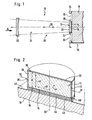
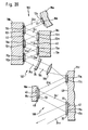
- An embodiment of a laser amplifier system according to the invention in Fig. 1 as a whole designated 10, comprises a radiation-enhancing Crystal 12 made of ytterbium-doped crystal material, which has a cooling surface 14, which in turn carries a reflector layer 16.
- This Reflector layer 16 is connected in a heat-conducting manner over its entire surface to a heat sink 18, so that the reflector layer 16 and the heat sink 18 together Form cooling element 20, on which the crystal 12 with its cooling surface 14 rests fully.
- the crystal 12 has a surface opposite the cooling surface 14 22, which is penetrated by a laser radiation field 24.
- This laser radiation field 24 forms on the one hand between a coupling-out mirror 26 and the reflector layer 16, which together as a whole form with 28 designated resonator, which the laser amplifier system 10th added to a laser system.
- the laser radiation field 24 of the resonator 28 thus penetrates the surface 22 of the crystal 12, enters it and is from the reflector layer 16 reflects on which the crystal 12 sits with its cooling surface 14.
- the crystal 12 also has side faces 30 which are transverse, preferably perpendicular to the cooling surface 14. These sides are from Pump light 32 penetrates from pump light radiation sources 34, the Pump light 32 for a volume excitation in the crystal 12, in particular in the area penetrated by the laser radiation field 24.
- the crystal 12 according to the invention sits with the Cooling surface 14 on the reflector layer 16, which preferably as highly reflective coating is applied to the cooling surface 14.
- the crystal 12 according to the invention bears on its cooling surface 14 opposite surface 22 an anti-reflective coating 36, which is designed to be anti-reflective for the laser radiation field 24.
- the side surfaces 30 are also anti-reflective Provide coating 38 which is anti-reflective for the pump light 32 is trained.
- the crystal according to the invention is preferably a Crystal disc, the cooling surface 14 formed as a circular disc is, and thus at least in one surface direction 40, one dimension which is larger, preferably several times larger than a thickness D of the crystal is measured in a direction 42 which is perpendicular to the Surface direction 40 stands.
- the reflector layer 16 is on its side facing away from the crystal 12 Side with a metallization 46, preferably made of copper, which in turn has a contact layer 48 made of soft metal - preferably soft solder or indium - with a support surface 49 of Heat sink is connected areal.
- the thermal conductivity of the cooling element 20 is greater than that of the Crystal, so that in the cooling element 20 more effective heat dissipation than in Crystal 12 takes place and in crystal 12 a temperature gradient parallel to Direction 42 arises, which is thus essentially parallel to a direction of propagation 25 of the laser radiation field 24 extends.
- the heat sink 18 with one in it extending cooling bore 50 which is provided with a bottom 52 in ends in an area 54 of the heat sink 18 which is adjacent to the crystal 12 lies.
- the cooling bore 50 preferably extends along an axis 56, to which the crystal 12 is also aligned coaxially.
- a pipe 58 protrudes into the cooling bore 50, which one inside the same lying inflow channel 60 and one between this and the Cooling bore 50 lying drain channel 62 forms.
- an opening 64 of the tube 58 points in the direction of the base 52, the bottom 52 is provided with a deflection cone 66, which is preferably is arranged coaxially to the axis 56 and thus centrally from the ground 52 protrudes towards the mouth 54.
- This deflection cone 66 forms its conical surface 68 deflection surfaces, which the cooling medium from the inflow channel 60 coming in the radial direction to the axis 56 to the outflow channel 62 redirect.
- This deflection cone 66 with the deflection surfaces 68 is an intense heat exchange between that through the inflow channel 60 incoming cooling medium and the heat sink 18, in particular its Area 54 possible, so that an efficient cooling of area 54 and thus also of the crystal 12 seated thereon via the cooling medium.
- the region 54 preferably has a thickness DI which is greater than that Quotient of the cooling surface 14 divided by its outer circumference AU, so that in the heat sink 18, the heat dissipation through an imaginary cylinder surface with the circumference U and the height DI is better than the heat dissipation the cooling surface 14 and thus also in the area 54 no heat accumulation enter.
- One is preferably through the conical surface 68, the bottom 52 and Wall surfaces of the bore 50 formed heat-emitting surface of the heat sink 18 many times larger than the cooling surface.
- water is used as the cooling medium.
- the cooling medium is preferably not one of the drawings in FIG. 3 shown cooling device supplied to the inflow channel 60 and from the Drain channel 62 discharged and cooled to a predetermined temperature.
- the coupling of the Pump light sources 34 delivered pump light 32 into the crystal 12 by means of Light guide 70 which starts from the pump light sources 34 in the direction of the crystal 12 and, for example, as shown in FIG. 5, with its near-crystal ends 74 at a short distance from the crystal 12 end up.
- the pump light 32 emerging from these near-crystal ends 74 diverges into a cone 71 until it hits the side surface 30 and is in Crystal 12 refracted again, so that the marginal radiation 73 of the Crystal 12 resulting cone with an angle ⁇ on the cooling surface 14 and the surface 22 occurs less than the angle of the critical angle of the Total reflection and these surfaces 14, 22 is.
- the pump light 32 thus becomes in the crystal 12 in the directions 40 or 44 guided by total reflection and has a substantially uniform Volume excitation of the entire crystal 12 result.
- the light guides 70 Preferably around the crystal 12 in a to an upper side 72 of the Heat sink 18 parallel plane and arranged the pump light sources 34 the light guides 70 also extend in a direction toward the carrier surface 49 parallel plane 72 from the pump light sources 34 to the side surfaces 30 of the crystal 12.
- the light guide 70 arranged so that it is close to the crystal Connect end 74 to each other in the area of their lateral surfaces.
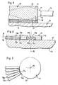
- An arrangement of the light guides 70 which is preferred, is even more advantageous are optical fibers, according to the configuration shown in Figs. 6 and 7.
- a level 76 Fibers 70a and fibers 70b arranged in a plane 78 are used, planes 76 and 78 also run parallel to support surface 49 and are preferably arranged so that the near-crystal ends 74b and 74a of the fibers 70a and 70b with their outer shells 80a and 80b, respectively touch and thereby the near-crystal ends 74a opposite the near-crystal Ends 74b and vice versa are arranged on gap.
- Fig. 8 lie the fibers 70 with their near-crystal ends 74 at a distance from the side surfaces 30 of the crystal 12 and between the near-crystal ends 74 and Side surfaces 30 are arranged as imaging optics lenses 82, which are made of the diverging pump light 84 emerging from the ends near the crystal 74 onto the Map side surfaces 30.
- Pump light sources 34 laser diodes used.
- FIG. 9 Another variant of the solution according to the invention, shown in FIG. 9, provides that only laser diodes are used as pump light sources 34, but none Light guide 70, but a diverging radiation cone 86, which consists of each of the laser diodes 34 emerges on the side surface by means of lens optics 88 30 of the crystal 12, preferably the lens optics 88 as a ring, coaxial to axis 56 and in a plane parallel to the top 72 arranged ring lens or ring-shaped cylindrical lens with convex Cross section is formed.
- FIG. 10 Another alternative variant, shown in FIG. 10, sees a paraboloid level 90 in front of the divergent radiation cone 86, which consists of a laser diode serving as pump light source 34 emerges by reflection images on the side surface 30 of the crystal 12.
- a paraboloid mirror 90 is rotationally symmetrical to the axis 56 annular and coaxial to the axis 56 and thus represents a segment of an annular toroid.
- FIG. 11 is rotationally symmetrical to axis 56 Variant of the solution according to the invention, the divergent Radiation cone 86 of a laser diode as a pump light source 34 by means of a lens 92 combined with a mirror 94 on the side surface 30 of the To map crystal 12.
- Pump light source 34 for example in the form of the laser diode next to the heat sink Arrange 18 and connect it to heat dissipation.
- FIG. 12 Another variant of the solution according to the invention can be seen as in FIG. 12 shown, before, the pump light sources 34 in the form of laser diodes directly to be arranged adjacent to the side surface 30, so that no coupling element is required and the emerging from these laser diodes 34 Pump light radiation directly into the crystal 12 to excite the crystal material occurs without an imaging element between the laser diodes 34 and the crystal 12 is provided.
- the pump light sources 34 in the form of laser diodes directly to be arranged adjacent to the side surface 30, so that no coupling element is required and the emerging from these laser diodes 34 Pump light radiation directly into the crystal 12 to excite the crystal material occurs without an imaging element between the laser diodes 34 and the crystal 12 is provided.
- the heat sink 18 does not have a flat carrier surface 49, but a concavely curved support surface 49 '.
- the cooling surface 14 'of the crystal 12' is shaped so that a reflector layer 16 lying over the entire surface on the carrier surface 49 ' essentially constant thickness in turn on the cooling surface 14 'rests fully.
- the one opposite to the cooling surface 14 ' is the same Surface 22 'is concave, so that the crystal 12 a has constant thickness D.
- FIG. 14 Variant of the solution according to the invention of the crystal 12 itself a convex surface 22 ", which acts as a crystalline lens.
- the cooling surface 14 is a flat surface in the same way as in the basic variant of the first shown in FIGS. 1 to 3, for example Embodiment.
- a further cooling element 120 sits on the surface 22, which in turn from a highly thermally conductive and transparent material, such as For example, silicon carbide is formed and one of the laser radiation field in the center 24 has penetrated area 118, on which outside areas 122 connect, which of a cooling medium, preferably Cooling water penetrated recesses 124 include, so that the Cooling medium flowing through recesses 124 is transported away Heat from the material of the outer areas 122 and in turn through them from the central region 118 penetrated by the laser radiation field 24 of the cooling element 120 takes place.
- the transparent cooling element be arranged in a ring, the recess for the cooling medium having.
- the crystal 12 is between the cooling element 120 and the Cooling element 20, formed from the heat sink 18 and the reflector layer 16 arranged and thus on both opposite surfaces, the is called the surface 22 and the cooling surface 14 cooled while over the Side surfaces 30 in a known manner, the coupling of the pump light 32 he follows.
- a second exemplary embodiment of an inventive device shown in FIG. 16 Laser amplifier differs from that shown in FIG. 1 Embodiment only in that the laser radiation field 24 that of a folded resonator and has two branches 24a and 24b, wherein resonator 28 has an end mirror 126, which is preferred is fully reflective.
- the branch 24a of the laser radiation field extends to the crystal 12, occurs through its surface 22 and into the reflector layer 16 reflected in the form of the second branch 24b, which on the decoupling mirror 26 hits and is partly reflected and partly by passes through this.
- the two branches 24a and 24b are pointed Angle a inclined relative to each other, so that a resonator axis 128 has two branches 128a and 128b which are at an acute angle to each other run.
- the advantage of the second embodiment is to be seen in that of the folded resonator in contrast to the first embodiment in the direction 42 can not form standing waves that in first embodiment to an uneven use of the excited Lead crystal.
- a third embodiment, shown in Fig. 17, comprises a laser amplifier, also designed as a laser with a multiply folded resonator, the laser radiation field a total of 3 branches 24c, 24d and 24e having.
- the branch 24c extends from a first reflector layer 16c with a crystal 12c sitting thereon to form a reflector layer 16d with a crystal 12d sitting on it.
- the second branch 24d extends to a reflector layer 16e with a crystal 12e sitting on it and from the reflector layer 16e the branch 24e of the laser radiation field 24 extends to the coupling-out mirror 26th
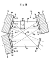
- the laser radiation field forms 24 a ring resonator, the first branch 24f of which goes out from the coupling-out mirror 26 to a reflector layer 16f with one thereon seated crystal 12f stretches.
- a second branch 24g Extends from this reflector layer 16f a second branch 24g to a reflector layer 16g with one in front of it Crystal 12g, a third extends from the reflector layer 16g Branch 24h to a reflector layer 16h with a crystal 12h in front of it, which has a convex surface 22.
- the convex surface 22 leads to a fourth branch 24i being focused in a focus 130, which in turn widens after focus 130 and onto the output mirror 26 hits.
- an optical diode 160 is provided, which a propagation of the radiation in the ring-shaped closed laser radiation field 24 only allows in one direction.
- a fifth embodiment shown in Fig. 19 is the structure Similar to the fourth embodiment, with the difference that in the Focus 130 still a doubler crystal 170 is arranged so that the laser wavelength of the laser is halved.
- optical diode 172 which is arranged in the branch 24f in this embodiment an etalon 174 is also provided, which is a narrow band Frequency tuning allowed. This etalon is also in, for example the branch 24f provided.
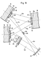
- two laser amplifier systems according to the invention are provided, namely once in a laser 180 with a resonator 182, which is formed by the coupling mirror 26 and a reflector layer 16k as End mirror.
- a first branch 24k extends Laser radiation field 24 to a reflector layer 16l, in front of which also a crystal 12l sits.
- a second branch 24l up to a reflector layer 16m in front of which likewise a crystal 12m sits, extends from the reflector layer 16m third branch 24m to a reflector layer 16n, in front of which a crystal 12n sitting.
- a fourth branch 24n extends from the reflector layer 16n up to a reflector layer 16o, in front of which a crystal 12o sits, from the reflector layer 16o a branch 24o extends to a reflector layer 16p, in front of which a crystal 12p sits and extends from the reflector layer 16p a branch 24p to the end mirror 26. All these elements form together the laser 180, the principle of that of the third embodiment 17 corresponds, wherein the end mirror 26 is a partially transparent Decoupling mirror is.
- a through the laser radiation field passing through the coupling mirror 26 24 emerging laser beam 184 is formed via a lens 186 reflected on a reflector layer 16q, in front of which a crystal 12q sits.
- the Reflector layer 16q in turn reflects with a slightly widened branch 24q to a reflector layer 16r, in front of which a crystal 12r sits and this again with a branch 24r to a reflector layer 16s, in front of which a Crystal 12s sits.
- the reflector layer 16s in turn reflects into a branch 24s, which ultimately represents the emerging, diverging laser beam.
- the reflector layers 16q to s and the crystals 12q to s form one as a whole with 188 designated laser amplifier, which the laser beam 184 additionally reinforced.
- the branches 24q to 24s diverge thus the reflector layers 16q to 16s and the crystals 12q to 12s with regard to their extension in the surface directions 40 and 44 dimension larger to the power density in the crystals 12q to 12s to keep approximately constant.
- the crystals become 12k to 12s corresponding to one of those in connection with the first embodiment described variants with pump light 32 from pump light sources 34 pumped.
- the reflector layers 16k to 16s each sit on their side a heat sink 18, for example there is the possibility of the Reflector layers 16l, 16n and 16p each on a single heat sink 18b to be arranged and in the same way also the reflector layers 16m and 16o to be arranged on a single heat sink 18c.
- the wings 49 of the heat sink are parallel aligned with each other and have flat surfaces.
- the crystal 12 with pump light 32 also over the surface 22, where, for example, a pump light beam emerging from a fiber bundle 192 194 is imaged on the crystal 12 by means of a lens 196, thereby at an acute angle to axis 56 through surface 22 in the crystal 12 occurs, is reflected by the reflector layer 16 and with a corresponding acute angle from the surface in the form of a emerging beam 198 emerges, which in turn via a Lens 200 is imaged on a retroreflective mirror 202 that the entire beam reflected back, so that a multiple passage of the Pump light 32 is ensured by the crystal to make the crystal 12 effective and as homogeneous as possible, approximately parallel to direction 42, in the To pump volume area penetrated by laser radiation field.
- a pump light beam emerging from a fiber bundle 192 194 is imaged on the crystal 12 by means of a lens 196, thereby at an acute angle to axis 56 through surface 22 in the crystal 12 occurs, is reflected by the reflector layer 16 and with a corresponding acute angle from the surface
- the volume area penetrated by the laser radiation field 24 pumping the crystal 12 in full is also provided that the angle with respect to the axis 56 with which the pump light beam 194 enters the crystal 12 is greater than the angle at which the laser radiation field 24 is inclined with respect to the axis 56.
- FIG. 21 the seventh exemplary embodiment shown in FIG. 21 is shown in FIG trained in the same way as the previous embodiments, so that full reference is made to the explanations on this can.
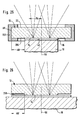
- isotherms I in one area PA excited by pump light 32 parallel to one another and parallel to Cooling surface 14 run, but in a radial direction with respect to axis 56 outside the area PA excited by the pump light 32
- Area R isotherms I in FIG. 22 isotherms I1 to I15, where I1 ⁇ I15 is to bend away from the cooling surface 14 towards the surface 22 run and at a preferably acute angle on the surface 22 hit.
- the solid body 12 is formed so that it with an outside area AB in the radial direction to the axis 56 beyond the cooling surface 14 extends and is not cooled in this outside area AB.
- the cooling surface 14 preferably extends on that of the surface 22 opposite side slightly above that excited by the pump light 32 Area PA in the radial direction to the axis 56 so that the Radius of the cooling surface 14 relative to the axis 56 is larger than that of the Pump light excited area PA.
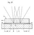
- Isotherms I'1 to I'15 run in the same way as in the Basic form of the seventh embodiment within that of the pump light excited area PA parallel to each other, due to the external Area AB of the solid 12 bend the isotherms I'1 to I'7 in the direction one in continuation of the cooling surface 14 and lying in the same plane Surface 204 of the outer area AB around and run in a pointed Angle to this. Furthermore, the isotherms I'8 to I'15 bend in the direction of the Surface 22 ⁇ m and close to it in a direction parallel to it this.
- the heat sink 18 is designed exactly as in the first variant and extends with the outer region AB beyond the cooling surface 14.
- the solid 12 is in the region of its outer edge AR of encompassed a temperature control ring 206, which the solid 12 in the area its outer edge AR supplies thermal energy and thus the solid in Area of its outer edge AR heats up to the outer edge AR reaching the course of the isotherms I '.
- the temperature control ring 206 is open, for example, by a heating element a temperature preheated in the range of the temperature of the isotherms I'7 and I'8 lies so that they extend to the outer edge AR and thereby simultaneously reducing the temperature gradient between I'1 and I'7 as well as I'8 and I'15 occurs.
- the heating of the solid body can also be done by irradiating the one to be heated Areas, for example with well absorbed by the solid Light, done.
- the thermal stresses can be avoided even more advantageously, if the temperature control ring 206 heats the surface 22 more than the surface 204 and in particular keeps the surface 204 at a temperature, which is approximately in the range of the temperature of the heat sink 18.
- the body is directly across the reflector layer 16 with the heat sink 18 thermally coupled cooling surface 14 reduced in that the Thickness of the reflector layer 16 in a radially outer with respect to the axis 56
- Area AB decreases so that one to the outer edge AR of the solid 12 widening gap 209 arises, which with a thermal is less well filled than the reflector layer conducting medium, so that the cooling power acting on the solid body 12 from the heat sink 18 in the outside area AB "continuously with increasing distance from the Axis 56 decreases to the outer edge AR and thus also one Heating of the solid 12 in the outer region AB "becomes possible, which in turn means that the isotherms run more evenly and a temperature gradient parallel to surface 22 either is smaller in amount than that in the basic form of the seventh embodiment or not one-sided, but similar to that in Fig.
- fiber bundle 192 emerges Pump light 32, which is first on a first pump light mirror 212 strikes, from this first pump light mirror 212 the pump light 32 in Form of a pump light beam 214 reflected on the solid body 12, penetrates the solid 12 to the reflector layer 16 between the solid 12 and the heat sink 18 and is in shape by the reflector layer 16 of an emerging beam 216 onto a second pump light mirror 218 which reflects the emerging beam 216 onto an auxiliary mirror 220 strikes, which in turn this emerging jet 216 on one reflects third pump light mirror 222, which in turn then in turn the pump light in the form of an incoming beam 224 onto the solid body reflects that this penetrates this and from the reflector layer 16 in Form of an emerging beam 226 onto a fourth pump light mirror 228 is reflected, which reflects the emerging beam 226 back into itself, so that this in turn enters the solid body 12, this penetrates from the reflector layer to the third pump light mirror 222 is reflected back from this to the auxiliary mirror 220, from this
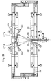
- the mechanical structure of the eighth exemplary embodiment shown in FIG. 28 comprises, as shown in partial section in Fig. 29, a housing 230 which holds an adjustable holder 232 for the fiber bundle 192, with which a beam direction 234 of the emerging from the fiber bundle 192 Pump light 32 is adjustable.
- an adjustable holder 236 for each on the housing 230 the pump light mirror 212, 218, 222 and 228 held.
- the pump light mirrors 212, 218, 222, 228 are adjustable so that the beam path described in connection with FIG. 28 arises, in addition, the auxiliary mirror 220 in turn also on an adjustable Holder 238 is seated and thus also opposite housing 230 is adjustable.
- the one on the heat sink 18 is not adjustable relative to the housing 230 sedentary solid 12, rather the entire beam path is relative to this solid 12 is adjusted with the individual holders 232, 236 and 238.
- a folded laser resonator is also in the eighth exemplary embodiment provided which is the same as in the seventh embodiment comprises both end mirrors 26 and 126 and forms a laser radiation field 24, which consists of the two branches 24a and 24b as a folded laser radiation field is trained.
- This laser radiation field 24 penetrates, as in the seventh embodiment already described, the solid 12 fourfold in order to get as possible to get effective coupling.
- FIG. 30 the corresponds to Structure essentially that of the eighth embodiment shown in FIG. 28, with the difference that instead of the auxiliary mirror 220 another solid 12 'with a reflector layer 16' not shown in the drawing which sits on a heat sink 18 ', so that with the same, pump light 32 emerging from the fiber bundle 192 excites two Solid 12 and 12 'is possible, which then both take up a laser activity.
- the one for the second one is shown in FIG. 30
- Solid body 12 ' Provided resonator with the corresponding radiation field 24 not shown, but this is constructed the same as that Resonator radiation field 24a and 24b following resonator with the mirrors 26 and 126.
- the ninth embodiment is designed in the same way like the eighth embodiment, so that full reference to this can be taken.
- a refractive index adaptive material 240 is provided, which has a refractive index between the the light guide 70 and the crystal 12 is located.
- this refractive index-adapting material 240 Divergence of the cone 71 emerging from the near-crystal end Pump lights 32 can be limited and on the other hand leads to the refractive index adapting Material 240 to ensure that in the plane 72 none on the side surfaces 30 reflected pump light radiation can occur, such as in the above exemplary embodiments could be the case because the Pump light radiation can be on the areas of the side surfaces where the Refractive index-adapting material 240 is no longer present Total reflection are reflected, but penetrates into the refractive index adapting Material 240 and can only on the environment Outer surfaces 242 are reflected. But there is none Possibility more that a circular reflection takes place in the plane 72 and thus formation of an undesired laser radiation field in this Level, which may be the case with the previous embodiments can.
- the laser radiation field 324 occurs in the same way as in the first Embodiment through the surface 322 and is by the Reflector layer 316 reflects.
- the pumping light 332 is also coupled in via two each other opposite side surfaces 330.
- the crystal 312 comprises one Inner area 360, which is doped with the laser-active substance and one Outside area 362, which is laser inactive and not for the laser radiation is absorbent.
- both areas have the same thermal and optical properties.
- the outer region 362 is opened, for example, with its inner surface 364 an outer surface 366 of the inner region 360 is bonded so that a gap-free Transition between interior 360 and exterior 362 consists.
- the inner surface 364 and the outer surface 366 preferably run at a Brewster angle to the cooling surface 314 of the crystal 312.
- the laser radiation field 324 does not only penetrate the interior 360, but also at least partially the outer area 362, from which a better mode structure when using the laser amplifier system according to the invention is available in a resonator of a laser system.
- the division of crystal 312 creates an interior 360 and an outside area 362 furthermore the possibility of being in to suppress level 72 by reflection-forming laser radiation.
- the crystal 312 according to the eleventh embodiment can be All of the above exemplary embodiments are used instead of the crystal 12 become.
- the side surfaces 330 ' are inclined and facing the cooling surface 314 Reflection surfaces for laterally, for example perpendicular to the cooling surface and next to this pump light 332 ', this pump light 332 'from an underside arranged in continuation of the cooling surface 314 368 of the outer region 362 of the crystal 312 into the outer region 362 enters and on the side surfaces 330 'towards the inner region 360 is reflected, the pumping light 332 likewise, as for example in the Described in connection with the second embodiment, in the way the total reflection at surface 322 and cooling surface 314 and partially spreads the underside 368 in the crystal 312 and thereby the laser-active inner area 360 penetrates so that the laser-active atoms or molecules of this inner region 360 are pumped.
- the laser radiation field 324 passes through in the same way as shown in FIG. not only the inner area 360 but at least parts of the outer area 362 and is reflected on the reflective layer 316.
- a cooling element 420 between each two crystals 412 is arranged on the one hand on the cooling surface 414 of the one crystal 412 rests and on the other hand on the surface 422 of the other crystal, so that the cooling elements 420 and the crystals 412 alternate with each other.
- the cooling elements 420 are made of a thermally conductive and transparent Material, such as silicon carbide.
- a laser radiation field 424 thereby spreads in one direction to the surfaces 414 and 422, which are each aligned parallel to one another.
- the cooling elements 420 are in a central one, from the laser radiation field 424 penetrated area 462 homogeneously transparent and only show in 464 recesses adjoin these laterally adjoining outer regions 466 for guiding cooling medium, for example cooling water.
- the transparent cooling element can be arranged in a ring be, which has the recess for the cooling medium.
- the outer regions 362 Possibility of doping them so that they emit light from a radiant heater, for example a heat lamp, absorb well, so that this embodiment particularly advantageous for one in connection with the seventh embodiment 23 to 27 described tempering a Outdoor area AB is suitable.
- the twelfth embodiment of a laser amplifier system according to the invention can either by providing end mirrors, which in the Direction 460 are arranged at a distance from each other, designed as a laser be or as a laser amplifier, which a penetrating laser radiation field 424 reinforced.
- the crystals ytterbium-doped crystals, preferably ytterbium-YAG or Ytterbium-FAP.
Landscapes
- Physics & Mathematics (AREA)
- Electromagnetism (AREA)
- Engineering & Computer Science (AREA)
- Plasma & Fusion (AREA)
- Optics & Photonics (AREA)
- Chemical & Material Sciences (AREA)
- Crystallography & Structural Chemistry (AREA)
- Nonlinear Science (AREA)
- Lasers (AREA)
Abstract
Description
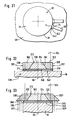
- Fig. 1
- ein erstes Ausführungsbeispiel eines erfindungsgemäßen Laserverstärkersystem als Teil eines Lasersystems;
- Fig. 2
- eine geschnittene perspektivische Darstellung eines erfindungsgemäßen Kristalls in derselben Darstellungsebene wie Fig. 1;
- Fig. 3
- eine vergrößerte Darstellung eines Kühlelements mit darauf sitzendem Kristall;
- Fig. 4
- eine Variante betreffend die Einkopplung von Pumplicht in den Kristall, dargestellt mit Blick in Richtung des Pfeils A in Fig. 1;
- Fig. 5
- einen Teillängsschnitt ähnlich Fig. 2 durch die in Fig. 4 dargestellte Variante;
- Fig. 6
- eine weitere Variante betreffend die Einkopplung von Pumplicht in den Kristall, dargestellt ähnlich Fig. 1;
- Fig. 7
- eine Draufsicht ähnlich Fig. 4 auf die weitere Variante;
- Fig. 8
- eine Draufsicht ähnlich Fig. 4 auf eine weitere Variante des ersten Ausführungsbeispiels betreffend die Einkopplung von Pumplicht in den Kristall;
- Fig. 9
- eine Darstellung ähnlich Fig. 1 einer weiteren Variante betreffend die Einkopplung von Pumplicht in den Kristall;
- Fig. 10
- eine weitere Variante betreffend die Einkopplung von Pumplicht in den Kristall, dargestellt ähnlich Fig. 1;
- Fig. 11
- eine weitere Variante betreffend die Einkopplung von Pumplicht in den Kristall in einer Darstellung ähnlich Fig. 1;
- Fig. 12
- eine weitere Variante des ersten Ausführungsbeispiels betreffend die Einkopplung von Pumplicht in den Kristall in einer Darstellung ähnlich Fig. 4;
- Fig. 13
- eine weitere Variante des ersten Ausführungsbeispiels betreffend die Form des Kristalls in einer Darstellung ähnlich Fig. 1;
- Fig. 14
- eine weitere Variante des ersten Ausführungsbeispiels betreffend die Form des Kristalls in einer Darstellung ähnlich Fig. 1;
- Fig. 15
- eine weitere Variante des ersten Ausführungsbeispiels betreffend die Kühlung des Kristalls in einer Darstellung ähnlich Fig. 1;
- Fig. 16
- ein zweites Ausführungsbeispiel eines erfindungsgemäßen Laserverstärkersystems als Teil eines Lasersystems;
- Fig. 17
- ein drittes Ausführungsbeispiel eines erfindungsgemäßen Laserverstärkersystems als Teil eines Lasersystems;
- Fig. 18
- ein viertes Ausführungsbeispiel eines erfindungsgemäßen Laserverstärkersystems als Teil eines Lasersystems;
- Fig. 19
- ein fünftes Ausführungsbeispiel eines erfindungsgemäßen Laserverstärkersystems als Teil eines Lasersystems;
- Fig. 20
- ein sechstes Ausführungsbeispiel eines erfindungsgemäßen Laserverstärkersystems umfassend ein System mit einem Laser und einem nachgeschalteten Laserverstärker;
- Fig. 21
- ein siebtes Ausführungsbeispiel eines erfindungsgemäßen Laserverstärkersystems als Lasersystem;
- Fig. 22
- eine schematische Darstellung von Isothermen im Festkörper gemäß dem siebten Ausführungsbeispiel;
- Fig. 23
- eine erste Variante des siebten Ausführungsbeispiels;
- Fig. 24
- eine Darstellung von Isothermen bei der ersten Variante des siebten Ausführungsbeispiels;
- Fig. 25
- eine schematische Darstellung einer zweiten Variante des siebten Ausführungsbeispiels ähnlich Fig. 21;
- Fig. 26
- eine dritte Variante des siebten Ausführungsbeispiels, dargestellt ähnlich Fig. 21;
- Fig. 27
- eine vierte Variante des siebten Ausführungsbeispiels, dargestellt ähnlich Fig. 21;
- Fig. 28
- ein achtes Ausführungsbeispiel eines erfindungsgemäßen Laserverstärkersystems als Lasersystem in schematischer Darstellung der optischen Komponenten;
- Fig. 29
- eine Schnittdarstellung durch einen Aufbau des achten Ausführungsbeispiels gemäß Fig. 28;
- Fig. 30
- eine Darstellung eines neunten Ausführungsbeispiels eines erfindungsgemäßen Laserverstärkersystems als Lasersystem ähnlich Fig. 28;
- Fig. 31
- eine Darstellung eines zehnten Ausführungsbeispiels eines erfindungsgemäßen Lasersystems als Laserverstärkersystem in einer Draufsicht ähnlich Fig. 4;
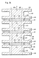
- Fig. 32
- ein elftes Ausführungsbeispiel eines erfindungsgemäßen Laserverstärkersystems, dargestellt in Schnittdarstellung;
- Fig. 33
- eine Variante des elften Ausführungsbeispiels gemäß Fig. 32 und
- Fig. 34
- ein zwölftes Ausführungsbeispiel eines erfindungsgemäßen Laserverstärkersystems.
- Tabelle 1
- eine Zusammenstellung von im Rahmen der erfindungsgemäßen Ausführungsbeispiele vorzugsweise einsetzbaren Festkörpermaterialien und Parametern derselben.
Claims (55)
- Laserverstärkersystem mit einem in einem Laserstrahlungsfeld angeordneten Festkörper, welcher ein laseraktives Material umfaßt, und mit einer Pumplichtquelle zum Pumpen des laseraktiven Materials, dadurch gekennzeichnet, daß der Festkörper (12, 212, 312, 412) plättchenförmig ausgebildet ist und mit mindestens einer Plättchenober- oder -unterseite als Kühloberfläche (14, 214, 314, 414) auf einem Kühlelement (20, 220, 320, 420) aufliegt, daß der Festkörper (12, 312, 412) eine quer zur Kühloberfläche (14, 314, 414) verlaufende Seitenfläche (30, 330, 430) aufweist, über welche eine Einkopplung des Pumplichts (32, 332, 432) erfolgt und daß auf der Seite des Festkörpers (12), auf welcher dieser die Kühloberfläche (14, 314) trägt, ein Reflektor (16, 316) für das Laserstrahlungsfeld (24, 324) angeordnet ist.
- Laserverstärkersystem nach Anspruch 1, dadurch gekennzeichnet, daß das Pumplicht (32, 332, 432) in dem plättchenförmigen Festkörper (12, 312, 412) durch Reflexion geführt ist.
- Laserverstärkersystem nach einem der voranstehenden Ansprüche, dadurch gekennzeichnet, daß die Einkopplung des Pumplichts (32) über eine der Kühloberfläche (14) gegenüberliegende Oberfläche (22) erfolgt und daß auf der Seite des Festkörpers (12), auf welcher die Kühloberfläche (14) liegt, ein Reflektor (16) für das Pumplicht (32) vorgesehen ist.
- Laserverstärkersystem nach Anspruch 3, dadurch gekennzeichnet, daß der Reflektor (16) für das Laserstrahlungsfeld (24) und der Reflektor (16) für das Pumplicht (32) miteinander identisch sind.
- Laserverstärkersystem nach Anspruch 3 oder 4, dadurch gekennzeichnet, daß das Pumplicht (32) den Festkörper (12) mindestens zweifach durchsetzt.
- Laserverstärkersystem nach Anspruch 5, dadurch gekennzeichnet, daß der vom Reflektor (16) reflektierte Pumplichtstrahl (198) wiederum durch einen Spiegel (202) in den Festkörper (12) zurück auf den Reflektor (16) reflektiert wird.
- Laserverstärkersystem nach einem der voranstehenden Ansprüche, dadurch gekennzeichnet, daß der Festkörper (12, 312,) mit der Kühloberfläche (14, 314) an dem Reflektor (16, 316) für das Laserstrahlungsfeld (24, 324) vollflächig anliegt.
- Laserverstärkersystem nach Anspruch 7, dadurch gekennzeichnet, daß über den Reflektor (16, 316) eine flächenhafte Wärmeeinleitung in einen Kühlkörper (18, 318) des Kühlelements (20, 320) erfolgt.
- Laserverstärkersystem nach einem der Ansprüche 7 oder 8, dadurch gekennzeichnet, daß der Reflektor (16, 316) eine auf die Kühloberfläche (14, 314) aufgetragene Reflektorschicht ist.
- Laserverstärkersystem nach einem der voranstehenden Ansprüche, dadurch gekennzeichnet, daß das Laserstrahlungsfeld (24, 324) von einer der Kühloberfläche (14, 314) gegenüberliegenden Oberfläche (22, 322) des Festkörpers (12, 312) in diesen eintritt.
- Laserverstärkersystem nach einem der voranstehenden Ansprüche dadurch gekennzeichnet, daß der Reflektor (16, 316) durch eine unmittelbar auf der Kühloberfläche (14, 314) des Festkörpers (12, 312) aufgebrachte hochreflektierende Reflektorschicht gebildet ist.
- Laserverstärkersystem nach Anspruch 11, dadurch gekennzeichnet, daß auf der dem Festkörper (12, 312) gegenüberliegenden Seite der Reflektorschicht (16, 316) eine Metallisierung (46) aufgebracht ist.
- Laserverstärkersystem nach Anspruch 12, dadurch gekennzeichnet, daß die Metallisierung (46) mit flächenhaftem Wärmekontakt mit dem Kühlkörper (18) verbunden ist.
- Laserverstärkersystem nach Anspruch 12 oder 13, dadurch gekennzeichnet, daß die Metallisierung (46) mittels eines weichen Metalls (48) mit dem Kühlkörper (18) verbunden ist.
- Laserverstärkersystem mit einem in einem Laserstrahlungsfeld angeordneten Festkörper, welcher ein laseraktives Material umfaßt, und mit einer Pumplichtquelle zum Pumpen des laseraktiven Materials, dadurch gekennzeichnet, daß der Festkörper (12, 212, 312, 412) plättchenförmig ausgebildet ist und mit mindestens einer Plättchenober- oder -unterseite als Kühloberfläche (14, 214, 314, 414) auf einem Kühlelement (20, 220, 320, 420) aufliegt, daß der Festkörper (12, 312, 412) eine quer zur Kühloberfläche (14, 314, 414) verlaufende Seitenfläche (30, 330, 430) aufweist, über welche eine Einkopplung des Pumplichts (32, 332, 432) erfolgt und daß das Pumplicht (32, 332, 432) in dem plättchenförmigen Festkörper (12, 312, 412) durch Reflexion geführt ist.
- Laserverstärkersystem nach einem der Ansprüche 5 bis 15, dadurch gekennzeichnet, daß das Pumplicht (32, 332, 432) in dem Festkörper (12, 312, 412) ungefähr parallel zur Kühloberfläche (14, 314, 414) geführt ist.
- Laserverstärkersystem nach Anspruch 16, dadurch gekennzeichnet, daß das Pumplicht (32, 332, 432) in dem Festkörper (12, 312, 412) durch die Kühloberfläche (14, 314, 414) und eine der Kühloberfläche gegenüberliegende Oberfläche (22, 322, 422) geführt ist.
- Laserverstärkersystem nach einem der Ansprüche 5 bis 17, dadurch gekennzeichnet, daß das Pumplicht (32, 332, 432) in dem Festkörper (12, 312, 412) durch Totalreflexion geführt ist.
- Laserverstärkersystem nach Anspruch 18, dadurch gekennzeichnet, daß die Divergenz des Pumplichts (32, 332, 432) im Festkörper (12, 312, 412) so groß ist, daß das Pumplicht (32, 332, 432) in einem Winkel nahe dem Grenzwinkel der Totalreflexion auf die dieses führende Oberflächen (14, 314, 414; 22, 322, 422) des Festkörpers (12, 312, 412) auftrifft.
- Laserverstärkersystem nach einem der voranstehenden Ansprüche, dadurch gekennzeichnet, daß das Laserverstärkersystem in Ebenen (72) parallel zur Kühloberfläche (49) für ein Laserstrahlungsfeld resonatorfrei ausgebildet ist.
- Laserverstärkersystem nach Anspruch 20, dadurch gekennzeichnet, daß angrenzend an die Seitenflächen (30, 330) ein brechungsindexadaptierendes Material (210) vorgesehen ist.
- Laserverstärkersystem nach Anspruch 21, dadurch gekennzeichnet, daß der Festkörper (312) einen das laseraktive Material aufweisenden Innenbereich (360) und einen vom laseraktiven Material freien Außenbereich (362) aufweist.
- Laserverstärkersystem nach Anspruch 22, dadurch gekennzeichnet, daß der Außenbereich (362) ein Material mit demselben Brechungsindex wie der Innenbereich (360) aufweist.
- Laserverstärkersystem nach Anspruch 22 oder 23, dadurch gekennzeichnet, daß der Außenbereich (362) und der Innenbereich (360) durch Bonden miteinander verbunden sind.
- Laserverstärkersystem nach einem der voranstehenden Ansprüche, dadurch gekennzeichnet, daß die Pumplichtquelle (34) eine oder mehrere Laser- oder Superstrahlungsdioden umfaßt.
- Laserverstärkersystem nach Anspruch 25, dadurch gekennzeichnet, daß das Pumplicht (32, 332, 432) der Laser- oder Superstrahlungsdiode (34) mit einem Lichtleiter (70) zum Festkörper (12, 312, 412) geführt ist.
- Laserverstärkersystem nach einem der voranstehenden Ansprüche, dadurch gekennzeichnet, daß die vom Pumplicht (32, 332, 432) durchsetzte Oberfläche (22, 30, 330, 430) des Festkörpers (12, 312, 412) mit einer Antireflexbeschichtung (38) versehen ist.
- Laserverstärkersystem nach einem der voranstehenden Ansprüche, dadurch gekennzeichnet, daß die vom Laserstrahlungsfeld (24, 324, 424) durchsetzte Oberfläche (22, 322, 422) des Festkörpers (12, 312, 412) mit einer Antireflexbeschichtung (36) versehen ist.
- Laserverstärkersystem nach einem der voranstehenden Ansprüche, dadurch gekennzeichnet, daß das Laserstrahlungsfeld (24, 424) mehrere der erfindungsgemäßen Festkörper (12, 412) durchsetzt.
- Laserverstärkersystem nach Anspruch 29, dadurch gekennzeichnet, daß in dem Laserverstärkersystem das Laserstrahlungsfeld (24) mehreren Reflexionen unterworfen ist und daß im Bereich von mehreren dieser Reflexionen ein Festkörper (12) angeordnet ist.
- Laserverstärkersystem nach Anspruch 30, dadurch gekennzeichnet, daß die Reflexionen jeweils an einem Reflektor (16) erfolgen, welcher von einem Kühlelement (20) für den jeweiligen Festkörper (12) umfaßt ist.
- Laserverstärkersystem nach einem der voranstehenden Ansprüche, dadurch gekennzeichnet, daß dieses mit einem Resonator (28) zu einem Lasersystem kombiniert ist.
- Laserverstärkersystem nach einem der voranstehenden Ansprüche dadurch gekennzeichnet, daß das Laserstrahlungsfeld (24, 324) in einem gefalteten Resonator (28) geführt ist.
- Laserverstärkersystem nach einem der voranstehenden Ansprüche, dadurch gekennzeichnet, daß der Festkörper (12, 212, 312, 412) über die Kühloberfläche (14, 214, 314, 414) in diesem entstehende Wärme flächenhaft auf ein massives Kühlelement (20, 220, 320, 420) ableitet, so daß in dem Festkörper (12, 212, 312, 412) ein Temperaturgradient in Richtung (42) auf die Kühloberfläche (14, 214, 314, 414) entsteht, daß das massive Kühlelement (20, 220, 320, 420) einen Träger für den Festkörper (12, 212, 312, 412) bildet und daß das Laserstrahlungsfeld (24, 224, 324, 424) sich ungefähr parallel zu dem Temperaturgradient im Festkörper (12, 212, 312, 412) ausbreitet.
- Laserverstärkersystem nach einem der voranstehenden Ansprüche, dadurch gekennzeichnet, daß das Kühlelement (20, 220, 320, 420) aus einem Material mit einer Wärmeleitfähigkeit ist, welche größer als die Wärmeleitfähigkeit des Festkörpers (12, 212, 312, 412) ist.
- Laserverstärkersystem nach einem der voranstehenden Ansprüche, dadurch gekennzeichnet, daß das Kühlelement (20, 220, 320, 420) in einem an den Festkörper (12, 212, 312, 412) angrenzenden Bereich senkrecht zur Kühloberfläche (14, 214, 314, 414) eine Dicke aufweist, welche größer ist als der Quotient aus der Fläche der Kühloberfläche (14, 214, 314, 414) dividiert durch deren Umfang (AU).
- Laserverstärkersystem nach einem der voranstehenden Ansprüche, dadurch gekennzeichnet, daß das Kühlelement (20, 220, 320, 420) eine Trägerfläche (49) für den Festkörper (12, 212, 312, 412) aufweist, welche größer als die Kühloberfläche (14, 214, 314, 414) ist.
- Laserverstärkersystem nach einem der voranstehenden Ansprüche, dadurch gekennzeichnet, daß die Kühloberfläche (14, 214, 314, 414) in einer ersten Richtung (40) eine Dimension aufweist, die größer ist als eine senkrecht zur Kühloberfläche (14, 214, 314, 414) gemessene Dicke (D) des Festkörpers (12, 212, 312, 412).
- Laserverstärkersystem nach einem der voranstehenden Ansprüche, dadurch gekennzeichnet, daß der Festkörper (12, 212, 312, 412) die in diesem entstehende Wärme von der Kühloberfläche (14, 214, 314, 414) vollflächig auf das Kühlelement (20, 220, 320, 420) ableitet.
- Laserverstärkersystem nach einem der voranstehenden Ansprüche, dadurch gekennzeichnet, daß das Kühlelement (20, 220, 320, 420) eine von einem Kühlmedium durchströmt ist.
- Laserverstärkersystem nach Anspruch 40, dadurch gekennzeichnet, daß das Kühlmedium eine Flüssigkeit ist.
- Laserverstärkersystem nach Anspruch 40 oder 41, dadurch gekennzeichnet, daß das Kühlmedium Kühlkanäle im Kühlelement (20, 220, 320, 420) durchsetzt.
- Laserverstärkersystem nach einem der Ansprüche 40 bis 42, dadurch gekennzeichnet, daß die vom Kühlmedium kontaktierte wärmeabgebende Fläche (50, 52, 68) ein Vielfaches der Fläche der Kühloberfläche (14, 214, 314, 414) beträgt.
- Laserverstärkersystem nach einem der voranstehenden Ansprüche, dadurch gekennzeichnet, daß der Temperaturgradient im Festkörper (12) in dem vom Laserstrahlungsfeld (24) durchsetzten Bereich quer zur Ausbreitungsrichtung des Laserstrahlungsfelds (24) im wesentlichen konstant ist.
- Laserverstärkersystem nach einem der voranstehenden Ansprüche, dadurch gekennzeichnet, daß der Temperaturgradient im Festkörper (12) in dem vom Pumplicht (32) durchsetzten Bereich (PA) quer zur Ausbreitungsrichtung des Laserstrahlungsfelds (24) im wesentlichen konstant ist.
- Laserverstärkersystem nach einem der voranstehenden Ansprüche, dadurch gekennzeichnet, daß der Festkörper (12) zu der Kühloberfläche (14) und der der Kühloberfläche (14) gegenüberliegenden Oberfläche (22) hin verlaufende Isothermen (I') aufweist.
- Laserverstärkersystem nach Anspruch 46, dadurch gekennzeichnet, daß der Verlauf der Isothermen (I') außerhalb eines vom Pumplicht (32) durchsetzten Bereichs (PA) einen parallel zur Kühloberfläche (14) und nahe derselben verlaufenden oberflächennahen Gradienten aufweist, welcher in vergleichbarer Größenordnung wie ein parallel zu der der Kühloberfläche (14) gegenüberliegenden Oberfläche (22) und nahe derselben verlaufender oberflächennaher Gradient ist.
- Laserverstärkersystem nach Anspruch 47, dadurch gekennzeichnet, daß die beiden oberflächennahen Gradienten im wesentlichen vergleichbar groß sind.
- Laserverstärkersystem nach einem der voranstehenden Ansprüche, dadurch gekennzeichnet, daß sich der Festkörper (12) in Richtung parallel zur Kühloberfläche (14) mit einem Außenbereich (AB) über diese hinauserstreckt.
- Laserverstärkersystem nach einem der voranstehenden Ansprüche, dadurch gekennzeichnet, daß sich die Kühloberfläche (14) in parallel zu dieser verlaufender Richtung mindestens über den vom Pumplicht (32) durchsetzten Bereich (PA) erstreckt.
- Laserverstärkersystem nach Anspruch 50, dadurch gekennzeichnet, daß sich die Kühloberfläche (14) in parallel zu dieser verlaufender Richtung über den vom Pumplicht (32) durchsetzten Bereich (PA) hinauserstreckt.
- Laserverstärkersystem nach einem der Ansprüche 49 bis 51, dadurch gekennzeichnet, daß der Festkörper (12) in einem außerhalb der Kühloberfläche (14) liegenden Bereichen (AB, AR) temperierbar ist.
- Laserverstärkersystem nach Anspruch 52, dadurch gekennzeichnet, daß der Festkörper (12) in seinem außerhalb der Kühloberfläche (14) liegenden Bereich (AB, AR) auf eine einen Temperaturgradient parallel zur Kühloberfläche (14) oder der zu dieser parallelen Oberfläche (22) reduzierende Temperatur temperierbar ist.
- Laserverstärkersystem nach Anspruch 52 oder 53, dadurch gekennzeichnet, daß der Festkörper (12) in einem außerhalb der Kühloberfläche (14) liegenden Bereich (AB, AR) auf eine über der Temperatur der Kühloberfläche (14) liegende Temperatur temperierbar ist.
- Laserverstärkersystem nach einem der Ansprüche 52 bis 53, dadurch gekennzeichnet, daß der Festkörper (12) in einem außerhalb der Kühloberfläche (14) liegenden Bereich (AB, AR) heizbar ist.
Applications Claiming Priority (6)
| Application Number | Priority Date | Filing Date | Title |
|---|---|---|---|
| DE4322094 | 1993-07-02 | ||
| DE4322094 | 1993-07-02 | ||
| DE4344227A DE4344227A1 (de) | 1993-07-02 | 1993-12-23 | Laserverstärkersystem |
| DE4344227 | 1993-12-23 | ||
| EP19940110179 EP0632551B1 (de) | 1993-07-02 | 1994-06-30 | Laserverstärkersystem |
| EP98107999A EP0869591B1 (de) | 1993-07-02 | 1994-06-30 | Laserverstärkersystem |
Related Parent Applications (3)
| Application Number | Title | Priority Date | Filing Date |
|---|---|---|---|
| EP98107999A Division EP0869591B1 (de) | 1993-07-02 | 1994-06-30 | Laserverstärkersystem |
| EP94110179.2 Division | 1994-06-30 | ||
| EP98107999.9 Division | 1998-04-30 |
Publications (3)
| Publication Number | Publication Date |
|---|---|
| EP1453157A2 true EP1453157A2 (de) | 2004-09-01 |
| EP1453157A3 EP1453157A3 (de) | 2004-09-15 |
| EP1453157B1 EP1453157B1 (de) | 2006-09-13 |
Family
ID=6491828
Family Applications (3)
| Application Number | Title | Priority Date | Filing Date |
|---|---|---|---|
| EP98107999A Expired - Lifetime EP0869591B1 (de) | 1993-07-02 | 1994-06-30 | Laserverstärkersystem |
| EP98108000A Expired - Lifetime EP0869592B1 (de) | 1993-07-02 | 1994-06-30 | Laserverstärkersystem |
| EP04012996A Expired - Lifetime EP1453157B1 (de) | 1993-07-02 | 1994-06-30 | Laserverstärkersystem |
Family Applications Before (2)
| Application Number | Title | Priority Date | Filing Date |
|---|---|---|---|
| EP98107999A Expired - Lifetime EP0869591B1 (de) | 1993-07-02 | 1994-06-30 | Laserverstärkersystem |
| EP98108000A Expired - Lifetime EP0869592B1 (de) | 1993-07-02 | 1994-06-30 | Laserverstärkersystem |
Country Status (3)
| Country | Link |
|---|---|
| US (1) | US5553088A (de) |
| EP (3) | EP0869591B1 (de) |
| DE (4) | DE4344227A1 (de) |
Cited By (2)
| Publication number | Priority date | Publication date | Assignee | Title |
|---|---|---|---|---|
| DE102008008078A1 (de) | 2008-01-28 | 2009-07-30 | Deutsches Zentrum für Luft- und Raumfahrt e.V. | Festkörper-Laser |
| US9985157B2 (en) | 2012-12-07 | 2018-05-29 | Deutsches Zentrum fuer Luft— und Raumfahrt e.V. | Optical energy transmission system |
Families Citing this family (118)
| Publication number | Priority date | Publication date | Assignee | Title |
|---|---|---|---|---|
| US6873639B2 (en) * | 1993-05-28 | 2005-03-29 | Tong Zhang | Multipass geometry and constructions for diode-pumped solid-state lasers and fiber lasers, and for optical amplifier and detector |
| DE19746835A1 (de) * | 1997-10-23 | 1999-05-06 | Jenoptik Jena Gmbh | Verfahren zum Montieren einer einseitig mit einer HR-Schicht beschichteten Laserkristallscheibe auf einen Kühlkörper und verfahrensgemäß hergestellte Schichtanordnung |
| AT408163B (de) * | 1998-02-25 | 2001-09-25 | Wintner Ernst Dr | Lasersystem zur erzeugung ultrakurzer lichtimpulse |
| US6418156B1 (en) | 1998-11-12 | 2002-07-09 | Raytheon Company | Laser with gain medium configured to provide an integrated optical pump cavity |
| US6347109B1 (en) * | 1999-01-25 | 2002-02-12 | The Regents Of The University Of California | High average power scaleable thin-disk laser |
| US6385220B1 (en) | 1999-04-21 | 2002-05-07 | Gsi Lumonics Inc. | Laser clamping assembly and method |
| DE19927054A1 (de) * | 1999-06-14 | 2000-12-28 | Rofin Sinar Laser Gmbh | Festkörperlaser |
| EP1196969B1 (de) * | 1999-07-02 | 2003-04-23 | Asah Medico A/S | Laserkristallvorrichtung |
| DE19939774C2 (de) * | 1999-08-21 | 2001-06-28 | Rofin Sinar Laser Gmbh | Festkörperlaser (Scheibenlaser) mit direktem Kontakt des aktiven Mediums zu einer Kühlmittelflüssigkeit |
| DE19946176B4 (de) * | 1999-09-21 | 2016-09-15 | Jenoptik Laser Gmbh | Diodengepumpter Laser mit interner Frequenzverdopplung |
| US6392791B1 (en) | 1999-10-25 | 2002-05-21 | University Of Alabama In Huntsville | Optical system and method for performing a defined function on an optical beam having at least one of a minimized volume or reduced operating temperature |
| DE10005195A1 (de) * | 2000-02-05 | 2001-08-16 | Univ Stuttgart Strahlwerkzeuge | Laserverstärkersystem |
| DE10005194A1 (de) * | 2000-02-05 | 2001-08-16 | Univ Stuttgart Strahlwerkzeuge | Laserverstärkersystem |
| US6339605B1 (en) * | 2000-02-16 | 2002-01-15 | The Boeing Company | Active mirror amplifier system and method for a high-average power laser system |
| JP3503588B2 (ja) | 2000-10-30 | 2004-03-08 | 澁谷工業株式会社 | 固体レーザ発振装置 |
| DE10054289A1 (de) * | 2000-11-02 | 2002-02-28 | Rofin Sinar Laser Gmbh | Festkörperlaser mit einem resonatorexternen Laserverstärker |
| US6625354B2 (en) | 2000-12-19 | 2003-09-23 | The Boeing Company | Fiber amplifier having a prism for efficient coupling of pump energy |
| US7200161B2 (en) * | 2001-01-22 | 2007-04-03 | The Boeing Company | Side-pumped solid-state disk laser for high-average power |
| US6625193B2 (en) | 2001-01-22 | 2003-09-23 | The Boeing Company | Side-pumped active mirror solid-state laser for high-average power |
| US6810060B2 (en) * | 2001-02-13 | 2004-10-26 | The Boeing Company | High-average power active mirror solid-state laser with multiple subapertures |
| US6603793B2 (en) | 2001-05-18 | 2003-08-05 | The Boeing Company | Solid-state laser oscillator with gain media in active mirror configuration |
| US6785304B2 (en) | 2001-07-24 | 2004-08-31 | Gsi Lumonics, Inc. | Waveguide device with mode control and pump light confinement and method of using same |
| DE10147798B4 (de) * | 2001-08-09 | 2015-12-31 | Trumpf Laser Gmbh | Laserverstärkersystem |
| DE10140254A1 (de) | 2001-08-09 | 2003-03-06 | Trumpf Laser Gmbh & Co Kg | Laserverstärkersystem |
| FR2842358B1 (fr) * | 2001-10-05 | 2004-08-27 | Sagem | AMPLIFICATEUR D'un FAISCEAU LASER PAR POMPAGE D'UN MATERIAU NON LINEAIRE ET DISPOSITIF D'EMISSION LASER COMPORTANT UNTEL AMPLIFICATEUR |
| DE10219004A1 (de) * | 2002-04-27 | 2003-11-13 | Rofin Sinar Laser Gmbh | Laserstrahlquelle mit einem eine dünne Kristallscheibe als laseraktives Medium enthaltenden Laserelement |
| FR2840461B1 (fr) * | 2002-05-28 | 2004-08-20 | Thales Sa | Systeme d'amplification laser a haute puissance |
| US7756172B2 (en) * | 2002-05-29 | 2010-07-13 | Osram Opto Semiconductors Gmbh | Optically pumped semi-conductive laser |
| US6891876B2 (en) * | 2002-08-30 | 2005-05-10 | Spectra Physics, Inc. | Method and apparatus for polarization and wavelength insensitive pumping of solid state lasers |
| US7003011B2 (en) * | 2002-08-30 | 2006-02-21 | Spectra Physics, Inc. | Thin disk laser with large numerical aperture pumping |
| US7027477B2 (en) * | 2002-08-30 | 2006-04-11 | Spectra Physics Inc. | Expansion matched thin disk laser and method for cooling |
| CN1685577A (zh) * | 2002-08-30 | 2005-10-19 | 光谱物理学公司 | 固体激光器的对偏振和波长不敏感的泵浦方法和装置 |
| US20060078030A1 (en) * | 2002-09-05 | 2006-04-13 | Konrad Altmann | Solid laser laterally pumped with focussed light from diodes in multiple flows |
| US20040076204A1 (en) | 2002-10-16 | 2004-04-22 | Kruschwitz Brian E. | External cavity organic laser |
| US6987789B2 (en) * | 2002-11-14 | 2006-01-17 | Hrl Laboratories, Llc | Multiple-disk laser system |
| US7330301B2 (en) * | 2003-05-14 | 2008-02-12 | Imra America, Inc. | Inexpensive variable rep-rate source for high-energy, ultrafast lasers |
| US7085304B2 (en) * | 2003-05-19 | 2006-08-01 | The Boeing Company | Diode-pumped solid state disk laser and method for producing uniform laser gain |
| JP2006526283A (ja) * | 2003-05-30 | 2006-11-16 | ハイ キュー レーザー プロダクション ゲゼルシャフト ミット ベシュレンクテル ハフツング | レーザーのポンピング方法とレーザー装置 |
| US20060050756A1 (en) * | 2003-06-20 | 2006-03-09 | Mitsubishi Denki Kabushiki Kaisha | Solid laser excitation module |
| US20060182162A1 (en) * | 2003-07-29 | 2006-08-17 | Takayuki Yanagisawa | Solid laser exciting module and laser oscillator |
| US20070166852A1 (en) * | 2003-09-22 | 2007-07-19 | Snake Creek Lasers Llc | Diode-pumped microlasers including resonator microchips and methods for producing the same |
| US20070121689A1 (en) * | 2003-09-22 | 2007-05-31 | Snake Creek Lasers Llc | Methods for Producing Diode-Pumped Micro Lasers |
| US20050105041A1 (en) * | 2003-10-02 | 2005-05-19 | Ira Lerner | Interchangeable eyewear assembly |
| US20050074040A1 (en) * | 2003-10-03 | 2005-04-07 | Spence David E. | Diamond cooled laser gain assembly |
| DE20316550U1 (de) * | 2003-10-27 | 2005-03-10 | High Q Laser Production Gmbh | Laserelement mit laseraktivem Medium |
| JP4402048B2 (ja) * | 2004-01-16 | 2010-01-20 | 三菱電機株式会社 | 固体レーザ励起モジュール及びレーザ発振器 |
| DE102004009593B4 (de) * | 2004-02-27 | 2006-11-23 | Rofin-Sinar Laser Gmbh | Festkörperlaser mit einer Kristallscheibe |
| DE102004012014B4 (de) * | 2004-03-11 | 2009-09-10 | Osram Opto Semiconductors Gmbh | Scheibenlaser mit einer Pumpanordnung |
| WO2005091448A1 (ja) * | 2004-03-24 | 2005-09-29 | Japan Science And Technology Agency | 固体レーザー装置の光ガイドの光入射窓 |
| WO2005091446A1 (ja) * | 2004-03-24 | 2005-09-29 | Japan Science And Technology Agency | 固体レーザー装置 |
| JP2006237540A (ja) * | 2004-03-30 | 2006-09-07 | Ricoh Co Ltd | 半導体レーザ励起固体レーザ装置 |
| ATE520046T1 (de) * | 2004-04-23 | 2011-08-15 | Olivier M Parriaux | Hocheffiziente optische beugungseinrichtung |
| DE102004040080B4 (de) * | 2004-07-29 | 2010-05-12 | Osram Opto Semiconductors Gmbh | Optisch gepumpte Halbleiter-Laservorrichtung |
| US20060083276A1 (en) * | 2004-09-28 | 2006-04-20 | Snake Creek Lasers, Llc. | Cryogenically cooled solid state lasers |
| US7310360B2 (en) * | 2004-10-25 | 2007-12-18 | The Boeing Company | Apparatus and method for face cooling of optical components of a laser system |
| JP2006165292A (ja) * | 2004-12-08 | 2006-06-22 | Ricoh Co Ltd | 半導体レーザ励起固体レーザ装置 |
| US7535633B2 (en) * | 2005-01-10 | 2009-05-19 | Kresimir Franjic | Laser amplifiers with high gain and small thermal aberrations |
| US8014433B2 (en) * | 2005-03-16 | 2011-09-06 | Apollo Instruments | Laser apparatuses with large-number multi-reflection pump systems |
| US20060209918A1 (en) * | 2005-03-16 | 2006-09-21 | Zhijiang Wang | High power thin disk lasers |
| JP4440812B2 (ja) * | 2005-03-17 | 2010-03-24 | 株式会社リコー | 半導体レーザ励起固体レーザ装置 |
| JP4608346B2 (ja) * | 2005-03-28 | 2011-01-12 | 株式会社リコー | 固体レーザ装置およびレーザ装置システム |
| US20080013586A1 (en) * | 2005-09-06 | 2008-01-17 | Spence David E | Narrow band diode pumping of laser gain materials |
| US7477674B2 (en) * | 2005-11-14 | 2009-01-13 | The Boeing Company | High-gain solid-state laser |
| US7463667B2 (en) * | 2005-11-22 | 2008-12-09 | The Boeing Company | Solid-state laser and multi-pass resonator |
| DE102006017294A1 (de) * | 2005-12-30 | 2007-07-05 | Osram Opto Semiconductors Gmbh | Optisch pumpbare Halbleitervorrichtung |
| FR2896921B1 (fr) * | 2006-01-31 | 2010-06-04 | Centre Nat Rech Scient | Dispositif de pompage longitudinal d'un milieu laser |
| DE102006006582B4 (de) * | 2006-02-13 | 2009-06-10 | Jenoptik Laser, Optik, Systeme Gmbh | Laser und Verfahren zur Erzeugung gepulster Laserstrahlung |
| JP2007311504A (ja) * | 2006-05-17 | 2007-11-29 | Ricoh Co Ltd | レーザー装置及びレーザー励起方法 |
| JP2008004752A (ja) * | 2006-06-22 | 2008-01-10 | Ricoh Co Ltd | レーザ結晶実装構造 |
| US20080009844A1 (en) * | 2006-06-26 | 2008-01-10 | Ingeborg Rolle | Device for Laser Surgery |
| JP2008010603A (ja) * | 2006-06-29 | 2008-01-17 | Ricoh Co Ltd | 半導体レーザ励起固体レーザ装置、光走査装置、画像形成装置及び表示装置 |
| DE102006056150A1 (de) * | 2006-11-28 | 2008-05-29 | Patent-Treuhand-Gesellschaft für elektrische Glühlampen mbH | Vorrichtung zur Abstrahlung elektromagnetischer Strahlung und Anzeigevorrichtung |
| DE102007004083A1 (de) * | 2006-12-22 | 2008-06-26 | Las-Cad Gmbh | Seitlich gepumpter Festkörperlaser |
| US7609741B2 (en) * | 2007-01-23 | 2009-10-27 | The Boeing Company | Disk laser including an amplified spontaneous emission (ASE) suppression feature |
| US7573930B2 (en) * | 2007-06-14 | 2009-08-11 | Innovavent Gmbh | Anamorphotic solid-sate laser |
| DE102007029242A1 (de) | 2007-06-22 | 2008-12-24 | Carl Baasel Lasertechnik Gmbh & Co. Kg | Laserstrahlquelle zum Erzeugen eines gepulsten Laserstrahls |
| US7826513B2 (en) * | 2007-08-30 | 2010-11-02 | The Boeing Company | Re-entrant structure for thin disk resonators |
| CA2750244C (en) * | 2008-01-03 | 2017-03-07 | Wi-Charge Ltd. | Wireless laser power transmitter |
| JP2010186793A (ja) * | 2009-02-10 | 2010-08-26 | Mitsubishi Electric Corp | 固体レーザーモジュール |
| US8035892B2 (en) * | 2009-04-01 | 2011-10-11 | The Boeing Company | Reliable startup of high power thin-disk laser resonators |
| US8379680B1 (en) | 2009-08-10 | 2013-02-19 | The Boeing Company | Direct cooling of thin disk lasers |
| WO2011027579A1 (ja) * | 2009-09-07 | 2011-03-10 | 三菱電機株式会社 | 平面導波路型レーザ装置 |
| WO2011027731A1 (ja) * | 2009-09-07 | 2011-03-10 | 三菱電機株式会社 | 平面導波路型レーザ装置 |
| US8605355B2 (en) * | 2009-11-24 | 2013-12-10 | Applied Energetics | Off axis walk off multi-pass amplifiers |
| US20110150013A1 (en) * | 2009-12-17 | 2011-06-23 | Coherent, Inc. | Resonant pumping of thin-disk laser with an optically pumped external-cavity surface-emitting semiconductor laser |
| JP2011146556A (ja) * | 2010-01-15 | 2011-07-28 | National Institutes Of Natural Sciences | 半導体レーザー励起固体レーザー装置 |
| WO2011091381A2 (en) * | 2010-01-22 | 2011-07-28 | Integral Laser Solutions, Llc. | Thin disk laser operation with unique thermal management |
| US8477410B2 (en) | 2011-02-08 | 2013-07-02 | Coherent, Inc. | Optical parametric oscillator pumped by femtosecond thin-disk laser |
| DE102011004204A1 (de) * | 2011-02-16 | 2012-08-16 | Trumpf Laser Gmbh + Co. Kg | Pumplichtanordnung für einen Scheibenlaser |
| US9077142B2 (en) * | 2011-03-15 | 2015-07-07 | Shanghai Jiao Tong University | Air-cooled laser device |
| US8908737B2 (en) | 2011-04-04 | 2014-12-09 | Coherent, Inc. | Transition-metal-doped thin-disk laser |
| WO2013019300A2 (en) * | 2011-05-11 | 2013-02-07 | Crystal Genesis, Llc | Laser design |
| EP2535988A3 (de) | 2011-06-16 | 2014-05-07 | Laser Quantum Inc. | Laser und optischer Verstärker |
| DE102011054024B4 (de) * | 2011-09-28 | 2014-10-09 | Deutsches Zentrum für Luft- und Raumfahrt e.V. | Infrarotlaserverstärkersystem |
| WO2014035525A2 (en) | 2012-06-12 | 2014-03-06 | Integral Laser Solutions, Llc. | Active cooling of high speed seeker missile domes and radomes |
| DE102012214971A1 (de) | 2012-08-23 | 2014-02-27 | Trumpf Laser Gmbh + Co. Kg | Festkörperlaseranordnung und Verfahren zu deren Herstellung |
| DE102012021169B4 (de) | 2012-10-29 | 2015-02-12 | Dausinger & Giesen Gmbh | Laserverstärkersystem mit angeklebter Festkörperscheibe |
| EP2932568B1 (de) | 2012-12-11 | 2021-10-27 | Koninklijke Philips N.V. | Optisch gepumpte festkörperlaservorrichtung mit selbstausrichtender pumpenoptik und erhöhter verstärkung |
| CN103219645B (zh) * | 2013-04-02 | 2015-05-20 | 大族激光科技产业集团股份有限公司 | 薄片激光器增益介质的冷却装置及激光器 |
| DE102013208377B4 (de) * | 2013-05-07 | 2016-05-12 | Forschungsverbund Berlin E.V. | Vorrichtung zur Verstärkung von gepulster Laserstrahlung mit hoher Energie der Laserpulse und hoher mittlerer Leistung |
| DE102013009509A1 (de) | 2013-05-29 | 2014-12-04 | Dausinger & Giesen Gmbh | Laserverstärkersystem, umfassend eine Festkörperscheibe mit thermischer Homogenisierungsschicht zur Wärmespreizung |
| JP2016015476A (ja) | 2014-06-11 | 2016-01-28 | キヤノン株式会社 | 面発光レーザアレイ、固体レーザ装置、およびそれを備えた被検体情報取得装置 |
| DE102015114263A1 (de) | 2015-08-27 | 2017-03-02 | Trumpf Laser Gmbh | Verspannungsoptimiertes Laserscheibenträgersystem |
| EP3364186B1 (de) * | 2015-10-14 | 2020-04-08 | Alps Alpine Co., Ltd. | Strömungswegstruktur und vorrichtung zur messung der flüssigkeit eines messobjekts |
| EP3185372A1 (de) | 2015-12-21 | 2017-06-28 | ETH Zurich | Mehrflutiger hochleistungslaseroszillator |
| DE102016114702B4 (de) | 2016-02-19 | 2019-12-05 | Deutsches Zentrum für Luft- und Raumfahrt e.V. | Laserverstärkungssystem und Verfahren zur Korrektur eines unsymmetrischen, transversalen Strahlungsdruckprofils in einem laseraktiven Medium eines Festkörpers |
| DE102016108474A1 (de) | 2016-05-09 | 2017-11-09 | Deutsches Zentrum für Luft- und Raumfahrt e.V. | Festkörper, Laserverstärkungssystem und Festkörperlaser |
| JP7021855B2 (ja) | 2017-02-08 | 2022-02-17 | 浜松ホトニクス株式会社 | レーザ媒質ユニット、及び、レーザ装置 |
| EP3657616B1 (de) * | 2018-02-26 | 2023-10-18 | Mitsubishi Heavy Industries, Ltd. | Festkörperlaser |
| JP7341673B2 (ja) * | 2019-02-27 | 2023-09-11 | 三菱重工業株式会社 | レーザ装置 |
| DE102019117880B4 (de) * | 2019-07-02 | 2024-04-18 | Deutsches Zentrum für Luft- und Raumfahrt e.V. | Lasersystem |
| JP7617632B2 (ja) * | 2019-07-31 | 2025-01-20 | 国立研究開発法人理化学研究所 | レーザセンサ |
| WO2021024457A1 (ja) * | 2019-08-08 | 2021-02-11 | 国立大学法人大阪大学 | レーザ増幅器 |
| DE102019219231A1 (de) * | 2019-12-10 | 2020-01-23 | Carl Zeiss Smt Gmbh | Projektionsbelichtungsanlage für die Halbleiterlithographie |
| DE102020122484B4 (de) * | 2020-08-27 | 2022-03-24 | Trumpf Laser- Und Systemtechnik Gmbh | Strahltransformator |
| DE102021003704A1 (de) * | 2020-10-18 | 2022-04-21 | Keming Du | Multipass-Pumpanordnung für Verstärker und Multipass-Verstärker mit großen Mode-Querschnitt |
| WO2023080205A1 (ja) * | 2021-11-04 | 2023-05-11 | 大学共同利用機関法人自然科学研究機構 | 光学素子、レーザ装置および光学素子の製造方法 |
| DE102023108777A1 (de) | 2023-04-05 | 2024-10-10 | Deutsches Zentrum für Luft- und Raumfahrt e.V. | Lasersystem, Verfahren zur Erzeugung wenigstens eines geformten und verstärkten Laserstrahls mit einem Lasersystem sowie optisches System |
Family Cites Families (13)
| Publication number | Priority date | Publication date | Assignee | Title |
|---|---|---|---|---|
| US3631362A (en) * | 1968-08-27 | 1971-12-28 | Gen Electric | Face-pumped, face-cooled laser device |
| US3638138A (en) * | 1970-06-25 | 1972-01-25 | Us Navy | Cadmium phosphide laser |
| US3753145A (en) * | 1972-06-26 | 1973-08-14 | Bell Telephone Labor Inc | Compact end-pumped solid-state laser |
| US4083018A (en) * | 1976-07-06 | 1978-04-04 | General Electric Company | Tunable laser system |
| US4429394A (en) * | 1981-11-09 | 1984-01-31 | Gte Products Corporation | Conduction cooled solid state laser |
| DE3617362A1 (de) * | 1986-05-23 | 1987-11-26 | Schott Glaswerke | Verbundmaterialien fuer die lasertechnik und optik |
| US4949342A (en) * | 1987-04-14 | 1990-08-14 | Matsushita Electric Industrial Co., Ltd. | Code error detecting method |
| US4990943A (en) * | 1989-07-03 | 1991-02-05 | Motorola, Inc. | PLZT Laser modulator |
| US4949346A (en) * | 1989-08-14 | 1990-08-14 | Allied-Signal Inc. | Conductively cooled, diode-pumped solid-state slab laser |
| US5267252A (en) * | 1991-08-30 | 1993-11-30 | Hoya Corporation | Solid-state laser device comprising a temperature-controlled thermal conductive support |
| DE4132063A1 (de) * | 1991-09-26 | 1993-04-08 | Deutsche Aerospace | Vorrichtung zur kuehlung von festkoerperlasern, insb. mikrokristallasern |
| US5181215A (en) * | 1991-11-22 | 1993-01-19 | Sam Richard C | Heated solid state laser |
| US5363391A (en) * | 1992-04-24 | 1994-11-08 | Hughes Aircraft Company | Conductive face-cooled laser crystal |
-
1993
- 1993-12-22 US US08/172,126 patent/US5553088A/en not_active Expired - Lifetime
- 1993-12-23 DE DE4344227A patent/DE4344227A1/de not_active Ceased
-
1994
- 1994-06-30 EP EP98107999A patent/EP0869591B1/de not_active Expired - Lifetime
- 1994-06-30 DE DE59410390T patent/DE59410390D1/de not_active Expired - Lifetime
- 1994-06-30 DE DE59410410T patent/DE59410410D1/de not_active Expired - Lifetime
- 1994-06-30 EP EP98108000A patent/EP0869592B1/de not_active Expired - Lifetime
- 1994-06-30 DE DE59407111T patent/DE59407111D1/de not_active Expired - Lifetime
- 1994-06-30 EP EP04012996A patent/EP1453157B1/de not_active Expired - Lifetime
Cited By (4)
| Publication number | Priority date | Publication date | Assignee | Title |
|---|---|---|---|---|
| DE102008008078A1 (de) | 2008-01-28 | 2009-07-30 | Deutsches Zentrum für Luft- und Raumfahrt e.V. | Festkörper-Laser |
| WO2009095311A1 (de) | 2008-01-28 | 2009-08-06 | Deutsches Zentrum für Luft- und Raumfahrt e.V. | Festkörper-laser |
| US8165182B2 (en) | 2008-01-28 | 2012-04-24 | Deutsches Zentrum Fuer Luft-Und Raumfahrt E.V. | Solid-state laser |
| US9985157B2 (en) | 2012-12-07 | 2018-05-29 | Deutsches Zentrum fuer Luft— und Raumfahrt e.V. | Optical energy transmission system |
Also Published As
| Publication number | Publication date |
|---|---|
| DE59410410D1 (de) | 2005-08-18 |
| EP0869592B1 (de) | 2004-09-22 |
| DE59407111D1 (de) | 1998-11-26 |
| DE4344227A1 (de) | 1995-01-19 |
| EP0869592A1 (de) | 1998-10-07 |
| EP0869591A1 (de) | 1998-10-07 |
| EP1453157B1 (de) | 2006-09-13 |
| DE59410390D1 (de) | 2004-10-28 |
| US5553088A (en) | 1996-09-03 |
| EP0869591B1 (de) | 2005-07-13 |
| EP1453157A3 (de) | 2004-09-15 |
Similar Documents
| Publication | Publication Date | Title |
|---|---|---|
| EP0869592B1 (de) | Laserverstärkersystem | |
| EP0632551B1 (de) | Laserverstärkersystem | |
| DE60218211T2 (de) | Laser mit einem verteilten verstärkungsmedium | |
| DE69606664T2 (de) | Optische gepumpter Festkörperlaserkopf | |
| DE69504407T2 (de) | Laser mit hoher Wiederholfrequenz für den mittleren Infrarotbereich | |
| DE19934638B4 (de) | Modensynchronisierter Festkörperlaser mit mindestens einem konkaven Faltungsspiegel | |
| DE19723269A1 (de) | Festkörperlaser mit einer oder mehreren Pumplichtquellen | |
| DE69804084T2 (de) | Thermisch verbesserter pumphohlraum mit integriertem konzetrator für bandleiterlaser | |
| DE4191708C1 (de) | Festkörperlaser | |
| DE10338417B3 (de) | Laser mit Laserverstärker mit einem scheibenförmigen aktiven Medium | |
| EP1188206B1 (de) | Festkörperlaser | |
| DE3604231C2 (de) | ||
| DE2456913A1 (de) | Farbstoff-laser | |
| EP0770275B1 (de) | Diodengepumpter hochleistungsfestkörperlaser | |
| EP0879494B1 (de) | Optisch gepumpter verstärker, insbesondere ein festkorper-verstärker | |
| DE69924544T2 (de) | Faserlaser | |
| DE60212377T2 (de) | System und verfahren zum pumpen eines plattenlasers | |
| DE69737119T2 (de) | Laserdiodengepumpter Festkörper Verstärker und Laser | |
| DE3829812C2 (de) | Festkörperlaser | |
| DE10344826A1 (de) | Festkörperlaser | |
| DE69704070T2 (de) | Plattenförmiger laseroszillator | |
| DE4008225A1 (de) | Laserdiodengepumpter festkoerperlaser | |
| DE69422988T2 (de) | Vorwärtskopplungsverstärker | |
| DE4229498A1 (de) | Festkörperlaser | |
| DE19521943C2 (de) | Festkörperlaservorrichtung |
Legal Events
| Date | Code | Title | Description |
|---|---|---|---|
| PUAI | Public reference made under article 153(3) epc to a published international application that has entered the european phase |
Free format text: ORIGINAL CODE: 0009012 |
|
| PUAL | Search report despatched |
Free format text: ORIGINAL CODE: 0009013 |
|
| AC | Divisional application: reference to earlier application |
Ref document number: 0632551 Country of ref document: EP Kind code of ref document: P Ref document number: 0869591 Country of ref document: EP Kind code of ref document: P |
|
| AK | Designated contracting states |
Kind code of ref document: A2 Designated state(s): DE FR GB IT |
|
| AK | Designated contracting states |
Kind code of ref document: A3 Designated state(s): DE FR GB IT |
|
| RIN1 | Information on inventor provided before grant (corrected) |
Inventor name: WITTIG, KLAUS Inventor name: VOSS, ANDREAS, DIPL.-PHYS. Inventor name: GIESEN, ADOLF, DR. RER. NAT Inventor name: BRAUCH, UWE, DR. |
|
| 17P | Request for examination filed |
Effective date: 20050304 |
|
| AKX | Designation fees paid |
Designated state(s): DE FR GB IT |
|
| 17Q | First examination report despatched |
Effective date: 20050628 |
|
| GRAP | Despatch of communication of intention to grant a patent |
Free format text: ORIGINAL CODE: EPIDOSNIGR1 |
|
| RAP1 | Party data changed (applicant data changed or rights of an application transferred) |
Owner name: UNIVERSITAET STUTTGART INSTITUT FUER STRAHLWERKZEU Owner name: DEUTSCHES ZENTRUM FUER LUFT- UND RAUMFAHRT E.V. |
|
| GRAS | Grant fee paid |
Free format text: ORIGINAL CODE: EPIDOSNIGR3 |
|
| GRAA | (expected) grant |
Free format text: ORIGINAL CODE: 0009210 |
|
| AC | Divisional application: reference to earlier application |
Ref document number: 0869591 Country of ref document: EP Kind code of ref document: P Ref document number: 0632551 Country of ref document: EP Kind code of ref document: P |
|
| AK | Designated contracting states |
Kind code of ref document: B1 Designated state(s): DE FR GB IT |
|
| PG25 | Lapsed in a contracting state [announced via postgrant information from national office to epo] |
Ref country code: IT Free format text: LAPSE BECAUSE OF FAILURE TO SUBMIT A TRANSLATION OF THE DESCRIPTION OR TO PAY THE FEE WITHIN THE PRESCRIBED TIME-LIMIT;WARNING: LAPSES OF ITALIAN PATENTS WITH EFFECTIVE DATE BEFORE 2007 MAY HAVE OCCURRED AT ANY TIME BEFORE 2007. THE CORRECT EFFECTIVE DATE MAY BE DIFFERENT FROM THE ONE RECORDED. Effective date: 20060913 |
|
| REG | Reference to a national code |
Ref country code: GB Ref legal event code: FG4D Free format text: NOT ENGLISH |
|
| REF | Corresponds to: |
Ref document number: 59410441 Country of ref document: DE Date of ref document: 20061026 Kind code of ref document: P |
|
| GBT | Gb: translation of ep patent filed (gb section 77(6)(a)/1977) |
Effective date: 20061113 |
|
| ET | Fr: translation filed | ||
| PLBE | No opposition filed within time limit |
Free format text: ORIGINAL CODE: 0009261 |
|
| STAA | Information on the status of an ep patent application or granted ep patent |
Free format text: STATUS: NO OPPOSITION FILED WITHIN TIME LIMIT |
|
| 26N | No opposition filed |
Effective date: 20070614 |
|
| PGFP | Annual fee paid to national office [announced via postgrant information from national office to epo] |
Ref country code: GB Payment date: 20130529 Year of fee payment: 20 |
|
| PGFP | Annual fee paid to national office [announced via postgrant information from national office to epo] |
Ref country code: FR Payment date: 20130618 Year of fee payment: 20 Ref country code: IT Payment date: 20130613 Year of fee payment: 20 |
|
| PGFP | Annual fee paid to national office [announced via postgrant information from national office to epo] |
Ref country code: DE Payment date: 20130628 Year of fee payment: 20 |
|
| REG | Reference to a national code |
Ref country code: DE Ref legal event code: R071 Ref document number: 59410441 Country of ref document: DE |
|
| REG | Reference to a national code |
Ref country code: DE Ref legal event code: R071 Ref document number: 59410441 Country of ref document: DE |
|
| REG | Reference to a national code |
Ref country code: GB Ref legal event code: PE20 Expiry date: 20140629 |
|
| PG25 | Lapsed in a contracting state [announced via postgrant information from national office to epo] |
Ref country code: GB Free format text: LAPSE BECAUSE OF EXPIRATION OF PROTECTION Effective date: 20140629 |
|
| PG25 | Lapsed in a contracting state [announced via postgrant information from national office to epo] |
Ref country code: DE Free format text: LAPSE BECAUSE OF EXPIRATION OF PROTECTION Effective date: 20140701 |