EP2932568B1 - Optisch gepumpte festkörperlaservorrichtung mit selbstausrichtender pumpenoptik und erhöhter verstärkung - Google Patents
Optisch gepumpte festkörperlaservorrichtung mit selbstausrichtender pumpenoptik und erhöhter verstärkung Download PDFInfo
- Publication number
- EP2932568B1 EP2932568B1 EP13795301.4A EP13795301A EP2932568B1 EP 2932568 B1 EP2932568 B1 EP 2932568B1 EP 13795301 A EP13795301 A EP 13795301A EP 2932568 B1 EP2932568 B1 EP 2932568B1
- Authority
- EP
- European Patent Office
- Prior art keywords
- laser
- solid state
- pump
- resonator
- state laser
- Prior art date
- Legal status (The legal status is an assumption and is not a legal conclusion. Google has not performed a legal analysis and makes no representation as to the accuracy of the status listed.)
- Active
Links
Images

Classifications
-
- H—ELECTRICITY
- H01—ELECTRIC ELEMENTS
- H01S—DEVICES USING THE PROCESS OF LIGHT AMPLIFICATION BY STIMULATED EMISSION OF RADIATION [LASER] TO AMPLIFY OR GENERATE LIGHT; DEVICES USING STIMULATED EMISSION OF ELECTROMAGNETIC RADIATION IN WAVE RANGES OTHER THAN OPTICAL
- H01S5/00—Semiconductor lasers
- H01S5/04—Processes or apparatus for excitation, e.g. pumping, e.g. by electron beams
- H01S5/041—Optical pumping
-
- H—ELECTRICITY
- H01—ELECTRIC ELEMENTS
- H01S—DEVICES USING THE PROCESS OF LIGHT AMPLIFICATION BY STIMULATED EMISSION OF RADIATION [LASER] TO AMPLIFY OR GENERATE LIGHT; DEVICES USING STIMULATED EMISSION OF ELECTROMAGNETIC RADIATION IN WAVE RANGES OTHER THAN OPTICAL
- H01S3/00—Lasers, i.e. devices using stimulated emission of electromagnetic radiation in the infrared, visible or ultraviolet wave range
- H01S3/02—Constructional details
- H01S3/025—Constructional details of solid state lasers, e.g. housings or mountings
-
- H—ELECTRICITY
- H01—ELECTRIC ELEMENTS
- H01S—DEVICES USING THE PROCESS OF LIGHT AMPLIFICATION BY STIMULATED EMISSION OF RADIATION [LASER] TO AMPLIFY OR GENERATE LIGHT; DEVICES USING STIMULATED EMISSION OF ELECTROMAGNETIC RADIATION IN WAVE RANGES OTHER THAN OPTICAL
- H01S3/00—Lasers, i.e. devices using stimulated emission of electromagnetic radiation in the infrared, visible or ultraviolet wave range
- H01S3/02—Constructional details
- H01S3/04—Arrangements for thermal management
- H01S3/042—Arrangements for thermal management for solid state lasers
-
- H—ELECTRICITY
- H01—ELECTRIC ELEMENTS
- H01S—DEVICES USING THE PROCESS OF LIGHT AMPLIFICATION BY STIMULATED EMISSION OF RADIATION [LASER] TO AMPLIFY OR GENERATE LIGHT; DEVICES USING STIMULATED EMISSION OF ELECTROMAGNETIC RADIATION IN WAVE RANGES OTHER THAN OPTICAL
- H01S3/00—Lasers, i.e. devices using stimulated emission of electromagnetic radiation in the infrared, visible or ultraviolet wave range
- H01S3/05—Construction or shape of optical resonators; Accommodation of active medium therein; Shape of active medium
- H01S3/06—Construction or shape of active medium
- H01S3/0602—Crystal lasers or glass lasers
- H01S3/0604—Crystal lasers or glass lasers in the form of a plate or disc
-
- H—ELECTRICITY
- H01—ELECTRIC ELEMENTS
- H01S—DEVICES USING THE PROCESS OF LIGHT AMPLIFICATION BY STIMULATED EMISSION OF RADIATION [LASER] TO AMPLIFY OR GENERATE LIGHT; DEVICES USING STIMULATED EMISSION OF ELECTROMAGNETIC RADIATION IN WAVE RANGES OTHER THAN OPTICAL
- H01S3/00—Lasers, i.e. devices using stimulated emission of electromagnetic radiation in the infrared, visible or ultraviolet wave range
- H01S3/09—Processes or apparatus for excitation, e.g. pumping
- H01S3/091—Processes or apparatus for excitation, e.g. pumping using optical pumping
- H01S3/094—Processes or apparatus for excitation, e.g. pumping using optical pumping by coherent light
- H01S3/0941—Processes or apparatus for excitation, e.g. pumping using optical pumping by coherent light of a laser diode
- H01S3/09415—Processes or apparatus for excitation, e.g. pumping using optical pumping by coherent light of a laser diode the pumping beam being parallel to the lasing mode of the pumped medium, e.g. end-pumping
-
- H—ELECTRICITY
- H01—ELECTRIC ELEMENTS
- H01S—DEVICES USING THE PROCESS OF LIGHT AMPLIFICATION BY STIMULATED EMISSION OF RADIATION [LASER] TO AMPLIFY OR GENERATE LIGHT; DEVICES USING STIMULATED EMISSION OF ELECTROMAGNETIC RADIATION IN WAVE RANGES OTHER THAN OPTICAL
- H01S5/00—Semiconductor lasers
- H01S5/10—Construction or shape of the optical resonator, e.g. extended or external cavity, coupled cavities, bent-guide, varying width, thickness or composition of the active region
- H01S5/14—External cavity lasers
- H01S5/141—External cavity lasers using a wavelength selective device, e.g. a grating or etalon
-
- H—ELECTRICITY
- H01—ELECTRIC ELEMENTS
- H01S—DEVICES USING THE PROCESS OF LIGHT AMPLIFICATION BY STIMULATED EMISSION OF RADIATION [LASER] TO AMPLIFY OR GENERATE LIGHT; DEVICES USING STIMULATED EMISSION OF ELECTROMAGNETIC RADIATION IN WAVE RANGES OTHER THAN OPTICAL
- H01S5/00—Semiconductor lasers
- H01S5/10—Construction or shape of the optical resonator, e.g. extended or external cavity, coupled cavities, bent-guide, varying width, thickness or composition of the active region
- H01S5/18—Surface-emitting [SE] lasers, e.g. having both horizontal and vertical cavities
- H01S5/185—Surface-emitting [SE] lasers, e.g. having both horizontal and vertical cavities having only horizontal cavities, e.g. horizontal cavity surface-emitting lasers [HCSEL]
- H01S5/187—Surface-emitting [SE] lasers, e.g. having both horizontal and vertical cavities having only horizontal cavities, e.g. horizontal cavity surface-emitting lasers [HCSEL] using Bragg reflection
-
- H—ELECTRICITY
- H01—ELECTRIC ELEMENTS
- H01S—DEVICES USING THE PROCESS OF LIGHT AMPLIFICATION BY STIMULATED EMISSION OF RADIATION [LASER] TO AMPLIFY OR GENERATE LIGHT; DEVICES USING STIMULATED EMISSION OF ELECTROMAGNETIC RADIATION IN WAVE RANGES OTHER THAN OPTICAL
- H01S5/00—Semiconductor lasers
- H01S5/30—Structure or shape of the active region; Materials used for the active region
- H01S5/34—Structure or shape of the active region; Materials used for the active region comprising quantum well or superlattice structures, e.g. single quantum well [SQW] lasers, multiple quantum well [MQW] lasers or graded index separate confinement heterostructure [GRINSCH] lasers
-
- H—ELECTRICITY
- H01—ELECTRIC ELEMENTS
- H01S—DEVICES USING THE PROCESS OF LIGHT AMPLIFICATION BY STIMULATED EMISSION OF RADIATION [LASER] TO AMPLIFY OR GENERATE LIGHT; DEVICES USING STIMULATED EMISSION OF ELECTROMAGNETIC RADIATION IN WAVE RANGES OTHER THAN OPTICAL
- H01S5/00—Semiconductor lasers
- H01S5/40—Arrangement of two or more semiconductor lasers, not provided for in groups H01S5/02 - H01S5/30
- H01S5/42—Arrays of surface emitting lasers
- H01S5/423—Arrays of surface emitting lasers having a vertical cavity
-
- H—ELECTRICITY
- H01—ELECTRIC ELEMENTS
- H01S—DEVICES USING THE PROCESS OF LIGHT AMPLIFICATION BY STIMULATED EMISSION OF RADIATION [LASER] TO AMPLIFY OR GENERATE LIGHT; DEVICES USING STIMULATED EMISSION OF ELECTROMAGNETIC RADIATION IN WAVE RANGES OTHER THAN OPTICAL
- H01S3/00—Lasers, i.e. devices using stimulated emission of electromagnetic radiation in the infrared, visible or ultraviolet wave range
- H01S3/05—Construction or shape of optical resonators; Accommodation of active medium therein; Shape of active medium
- H01S3/06—Construction or shape of active medium
- H01S3/07—Construction or shape of active medium consisting of a plurality of parts, e.g. segments
-
- H—ELECTRICITY
- H01—ELECTRIC ELEMENTS
- H01S—DEVICES USING THE PROCESS OF LIGHT AMPLIFICATION BY STIMULATED EMISSION OF RADIATION [LASER] TO AMPLIFY OR GENERATE LIGHT; DEVICES USING STIMULATED EMISSION OF ELECTROMAGNETIC RADIATION IN WAVE RANGES OTHER THAN OPTICAL
- H01S3/00—Lasers, i.e. devices using stimulated emission of electromagnetic radiation in the infrared, visible or ultraviolet wave range
- H01S3/05—Construction or shape of optical resonators; Accommodation of active medium therein; Shape of active medium
- H01S3/08—Construction or shape of optical resonators or components thereof
- H01S3/08059—Constructional details of the reflector, e.g. shape
- H01S3/08068—Holes; Stepped surface; Special cross-section
-
- H—ELECTRICITY
- H01—ELECTRIC ELEMENTS
- H01S—DEVICES USING THE PROCESS OF LIGHT AMPLIFICATION BY STIMULATED EMISSION OF RADIATION [LASER] TO AMPLIFY OR GENERATE LIGHT; DEVICES USING STIMULATED EMISSION OF ELECTROMAGNETIC RADIATION IN WAVE RANGES OTHER THAN OPTICAL
- H01S5/00—Semiconductor lasers
- H01S5/005—Optical components external to the laser cavity, specially adapted therefor, e.g. for homogenisation or merging of the beams or for manipulating laser pulses, e.g. pulse shaping
- H01S5/0071—Optical components external to the laser cavity, specially adapted therefor, e.g. for homogenisation or merging of the beams or for manipulating laser pulses, e.g. pulse shaping for beam steering, e.g. using a mirror outside the cavity to change the beam direction
-
- H—ELECTRICITY
- H01—ELECTRIC ELEMENTS
- H01S—DEVICES USING THE PROCESS OF LIGHT AMPLIFICATION BY STIMULATED EMISSION OF RADIATION [LASER] TO AMPLIFY OR GENERATE LIGHT; DEVICES USING STIMULATED EMISSION OF ELECTROMAGNETIC RADIATION IN WAVE RANGES OTHER THAN OPTICAL
- H01S5/00—Semiconductor lasers
- H01S5/02—Structural details or components not essential to laser action
- H01S5/022—Mountings; Housings
- H01S5/023—Mount members, e.g. sub-mount members
- H01S5/02325—Mechanically integrated components on mount members or optical micro-benches
Definitions
- the present invention relates to an optically pumped solid state laser device comprising one or several solid state laser media in a laser resonator and one or several pump laser diodes to optically pump the solid state laser media, said laser resonator being formed of one or several first resonator mirrors arranged at a first side of said solid state laser media and one or several second resonator mirrors arranged at an opposing second side of said solid state laser media, said first and second resonator mirrors being arranged to guide laser radiation of said laser resonator on at least two different straight paths through each of said laser media.
- optically pumped solid state laser devices of this kind are optically pumped vertical extended cavity surface emitting lasers (VECSELs) or semiconductor disc lasers (SDL) which offer a compact and low-cost solution for medium laser powers with high brightness, narrow bandwidth and short laser pulses.
- VECSELs vertical extended cavity surface emitting lasers
- SDL semiconductor disc lasers
- Such laser devices can be used for a huge number of applications requiring higher brightness and/or shorter pulses than can be delivered by laser diodes.
- Standard disc lasers need precise alignment of the pump lasers and the pump laser optics with respect to the optical mode of the laser resonator. This alignment is difficult during the fabrication of the laser device. Furthermore, such lasers are often limited in the power of the low brightness pump radiation that can be focused in a given active area of the laser medium which results in a low gain of the laser device. Also the maximum dissipated power density in the laser medium is often limited by the cooling method, in particular a heat sink onto which the laser medium is mounted.
- US 5,553,088 A discloses a solid state laser device comprising one or several disc shaped solid state laser media in a laser resonator.
- the laser resonator in at least one of the embodiments is formed of a first resonator mirror formed of a first end face of the solid state laser medium and several second resonator mirrors arranged at an opposing second side of the solid state laser medium.
- the resonator mirrors are arranged to guide the laser radiation of the laser resonator on two different paths through the laser medium.
- the laser medium is pumped by several laser diodes from the side which are arranged at the same carrier element as the solid state laser medium.
- the proposed device allows an enhanced gain of the laser medium due to the propagation of the laser radiation on different paths through the laser medium. This also allows a better distribution of the generated heat and results in an improved cooling.
- the document does not propose any solution for an easier alignment of the pump optics in case of optical pumping through one of the end faces of the laser medium through which the laser radiation passes
- DE 197 28 845 A1 discloses a laser amplifier which includes an active solid state material.
- One or more pumping beams are fed via mirrors or other optical devices, such that each individual pumping beam is focussed onto different parts of the material multiple times.
- the laser beam is fed so that all these parts are irradiated and thus amplified.
- the solid-state material is composed of several blocks of the same base material, but in part doped and in part undoped such that the pumping beam is absorbed only in the doped blocks.
- the blocks are connected together by diffusion bonding after polishing of the surfaces, so that the mechanical cohesion is comparable to that of the solid-state material.
- JP 2006 165292 A and JP 2003 060299 A disclose multifunctional integral optical elements comprising different surfaces acting for different purposes of beam transmission and reflection.
- optically end-pumped solid state laser device according to claim 1.
- Advantageous embodiments of the device are subject matter of the dependent claims or can be deduced from the subsequent portions of the description and preferred embodiments.
- the proposed optically end-pumped solid state laser device comprises one or several preferably disc or plate shaped solid state laser media in a laser resonator.
- the laser resonator is formed of one or several first resonator mirrors arranged at a first side of the solid state laser media and one or several second resonator mirrors arranged at a second side of the solid state laser media opposing said first side.
- the first and second resonator mirrors are arranged to guide the laser radiation of the laser device on at least two different straight paths through each of said laser media.
- the laser can be designed for example to be a VECSEL wherein each laser medium is formed of a quantum-well structure on a DBR (distributed Bragg reflector) which forms one of the first resonator mirrors or a disc laser.
- DBR distributed Bragg reflector
- One or several laser pump laser diodes and pump radiation reflecting mirrors are arranged to optically pump the solid state laser media by reflection of the pump radiation of the pump laser diodes at said pump radiation reflecting mirrors.
- the pump radiation reflecting mirrors are situated on the second side together with the second resonator mirrors and are arranged and designed to directly reflect the pump radiation to the end faces of the solid state laser media on the second side.
- the pump reflecting mirrors and the second resonator mirrors are integrally formed in a single mirror element on the second side of the solid state laser media.
- the first resonator mirror or resonator mirrors may be formed of the end faces of the laser media on the first side. To this end, the end faces of crystalline laser media may be appropriately coated to achieve a high reflection of the laser radiation at these end faces.
- the first resonator mirrors are formed of the DBR(s) on which the laser medium (active medium) is arranged.
- the solid state laser device of the present invention uses an appropriately designed mirror element which directs the pump light into the solid state laser media and at the same time forms the second resonator mirrors of the laser resonator.
- the pump radiation mirrors formed in this mirror element are designed to pump the areas of the laser media which cover the modes of the laser radiation on the different paths through these laser media. Therefore, the pump beams and the laser mode always overlap without complicated alignment since the parts of the mirror element forming the pump optics are always in a fixed spatial relationship to the parts of the mirror element forming the second resonator mirrors. With such a self-centering mirror element the alignment of the pump optics is significantly simplified.
- the proposed design allows the arrangement of the pump laser diodes close to the laser media resulting in a very compact design of the solid state laser device. Due to the different paths of the laser radiation through the solid state laser media, a higher amount of pump energy can be deposited resulting in an enhanced gain of the laser device compared with a similar laser in which the laser radiation always propagates on the same path through the laser medium. The different paths also allow a better heat distribution and thus a better cooling of the solid state laser device.
- the cooling is preferably achieved through cooling body with a plane surface onto which the laser media are mounted adjacent to each other.
- the pump laser diodes may also be mounted on this cooling body adjacent to and/or between the solid state laser media.
- the pump laser diodes then emit the pump radiation substantially perpendicular to the end faces of the solid state laser media towards the mirror element.
- the cooling body may be a heat sink of a bulk material, in particular a metal, and may also have cooling fins for air cooling. It is also possible to realize this cooling body as a chamber for a cooling liquid, for example water, which is pumped through the cooling body during operation of the laser device.
- the pump laser diodes maybe single diodes or arrays of laser diodes, for example vertical cavity surface emitting laser (VCSEL) arrays or microchip-VECSEL arrays.
- the body of the mirror element is preferably formed of an optically transparent material, for example a coated glass or coated plastics.
- the coating for the mirrors may be formed of a metallic coating or of a dielectric coating as known in the art.
- the proposed laser device may comprise at least two solid state laser media mounted adjacent to each other on an appropriate carrier element, in particular a cooling body. Each of these laser media are preferably surrounded by several pump laser diodes on the carrier element.
- the mirror element may then comprise one pump radiation reflecting mirror for each of said laser media, said pump radiation reflecting mirror being preferably centered with respect to the corresponding laser media. On the mirror element, these pump radiation reflecting mirrors are arranged between the second resonator mirrors which reflect the laser radiation coming from one of the laser media to the adjacent laser medium. This results in a zig-zag-path of the laser radiation between the first and second resonator mirrors through the laser device and in the different straight paths through the laser media.
- the pump laser diodes and pump radiation reflecting mirrors are arranged and designed such that each of these paths is sufficiently optically pumped to achieve the required gain.
- One of the two outer resonator mirrors of the mirror element is designed to form the outcoupling mirror of the laser resonator. This means that this mirror allows the passage of a small portion of the laser radiation through the mirror to the outside of the laser resonator.
- the proposed solid state laser device comprises one single solid state laser medium arranged on an appropriate carrier element.
- the solid state laser medium is preferably surrounded by several pump laser diodes on said carrier element.
- the mirror element may comprise a central region which forms the second resonator mirrors and an outer region which is designed to reflect the pump radiation to the solid state laser medium and forms the pump radiation reflecting mirror(s).
- the laser radiation may be guided on substantially more than two different paths through the laser medium, resulting in a zig-zag-path of the laser radiation between the first and second resonator mirrors through the laser device like that in the previous embodiment.
- the outer region of the mirror element is then designed to generate an intensity distribution of the pump radiation at the facing end face of the solid state laser medium which covers the modes of all of the different paths of the laser radiation through this laser medium.
- one of the second resonator mirrors is designed to form the outcoupling mirror of the laser resonator.
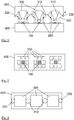
- FIG 1 shows a cross sectional side view of a first example of the proposed solid state laser device.
- the laser device comprises three plate shaped solid state laser media 100 mounted side by side on a plane surface of a heat sink 400.
- Each of these laser media 100 may be formed of the active area of a VCSEL and is surrounded by several pump laser diodes 200 as can be recognized from the top view onto the laser media and heat sink shown in figure 2 .
- the laser resonator in this example is formed of seven resonator mirrors arranged on both sides of the laser media.
- the first resonator mirrors are formed of the DBRs of the VCSELs which provide the laser media 100.
- the end mirror 320, the outcoupling mirror 330 and two folding mirrors 310 are arranged on the opposing second side of the laser media 100.
- the laser radiation 500 propagates on a zig-zag-path through the laser device.
- Each of the laser media 100 is passed on two different paths.
- the arrangement also comprises three pump radiation reflecting mirrors 300 which are arranged and designed to direct the pump radiation 510 towards the end faces of the laser media 100.
- the second resonator mirrors 310, 320, 330 are integrally formed together with the pump radiation reflecting mirrors 300 in one single optical element 600. Since this optical element can be fabricated with high precision, the relative orientation and arrangement between the pump radiation reflecting mirrors 300, i.e.
- the pump radiation reflecting mirrors are formed of three parabolic surfaces as indicated in figure 1 .
- the radiation of the pump laser diodes 200 is thus reflected and focused on the active media (laser media 100) and overlaps with the optical mode of the resonator in these media.
- Figure 3 shows a top view on the optical element 600 in which the adjacent arrangement of the pump radiation reflecting mirrors 300 and the second laser mirrors, end mirror 320, folding mirrors 310 and outcoupling mirror 330, can be recognized.
- the three laser media 100 could also be replaced by a single, rectangular shaped active medium extending between the two outer laser media 100 of figure 1 .
- the pump laser diodes 200 would then be located along the long edges of the rectangular laser medium.
- the mirror element 600 would provide the folding mirrors 310 directly adjacent to each other with the pump mirrors 300 on both sides.
- this is only one of several further possibility of an arrangement according to the present invention.
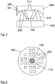
- Figure 4 shows a side view of a second example of the proposed solid state laser device.
- only one solid state laser medium 100 is arranged on a plane surface of a heat sink 400.
- This solid state laser medium is surrounded by several pump laser diodes on the same surface of the heat sink 400.
- An example for such an arrangement of the pump laser diodes 200 is shown in the top view on the solid state laser medium 100 in figure 5 .
- the mirror element 600 in this embodiment comprises an outer section 301 reflecting the pump radiation onto the end face of the solid state laser medium 100.
- the central portion 311 of the mirror element 600 forms the second resonator mirrors.
- the radiation of all pump laser diodes 200 is focused by the pump radiation reflecting mirror(s) in outer portion 301 of the mirror element 600 on a single spot 110 which is larger than the typical mode size of the resonator (see figure 5 ).
- a pumped area much larger than the mode size would result in multimode operation with a reduced brightness.
- a circular arrangement of several folding mirrors 310 reflects the laser mode at several different positions through the pumped area 110. This arrangement of the folding mirrors 310 is shown in the top view on the reflecting side of the mirror element 600 shown in figure 6 .
- Figure 7 shows the optical paths of the laser radiation in a cross sectional view along circular line A indicated in figure 6 .
- this cross sectional view also the end mirror 320 and the outcoupling mirror 330 of the laser resonator are indicated. Since figure 7 shows a cross section along a circular line, the resonator end mirror 320 and the outcoupling mirror 330 are arranged adjacent to each other on the mirror element 600. It is obvious for the skilled person that also the central part of the pumped area can be filled with the optical mode by an appropriate arrangement of the folding mirrors 310.
Landscapes
- Physics & Mathematics (AREA)
- Electromagnetism (AREA)
- Optics & Photonics (AREA)
- Condensed Matter Physics & Semiconductors (AREA)
- General Physics & Mathematics (AREA)
- Engineering & Computer Science (AREA)
- Plasma & Fusion (AREA)
- Chemical & Material Sciences (AREA)
- Crystallography & Structural Chemistry (AREA)
- Lasers (AREA)
- Semiconductor Lasers (AREA)
Claims (10)
- Optisch gepumptes Festkörperlasergerät, das Folgendes umfasst:- mindestens ein Festkörperlasermedium (100) in einem Laserresonator, wobei der Laserresonator aus einem VCSEL oder einem Halbleiter-Scheibenlaser besteht,- wobei der Laserresonator aus mindestens einem ersten Resonatorspiegel an einer ersten Seite des Festkörperlasermediums (100) sowie aus mindestens einem zweiten Resonatorspiegel (310, 320, 330) an einer zweiten, der ersten Seite gegenüberliegenden Seite des Festkörperlasermediums (100) besteht, wobei die ersten Resonatorspiegel aus verteilten Bragg-Reflektoren bestehen, auf denen sich die Festkörperlasermedien (100) befinden,- wobei die ersten und zweiten Resonatorspiegel (310, 320, 330) die Laserstrahlung (500) des Laserresonators auf mindestens zwei verschiedenen geraden Wegen durch die einzelnen Lasermedien (100) führen,- mindestens eine Pumplaserdiode (200) und mindestens ein reflektierende Pumpstrahlungsspiegel (300),- wobei die Pumplaserdioden (200) das Festkörperlasermedium (100) optisch pumpen, indem die Pumpstrahlung (510) von den reflektierenden Pumpstrahlungsspiegeln (300) reflektiert wird,- wobei die reflektierenden Pumpstrahlungsspiegel (300) auf der zweiten Seite angeordnet sind und die Pumpstrahlung (510) direkt auf das Festkörperlasermedium (100) reflektieren,- wobei die reflektierenden Pumpstrahlungsspiegel (300) und die zweiten Resonatorspiegel (310, 320, 330) ein einziges Spiegelelement (600) bilden, und- wobei die zweiten Resonatorspiegel (310, 320, 330) einen Auskopplungsspiegel (330) umfassen, der eines Teil der Laserstrahlung (500) durch den Auskopplungsspiegel (330) zur Außenseite des Laserresonators gelangen lässt.
- Das Gerät gemäß Anspruch 1,
wobei die Festkörperlasermedien (100) nebeneinander auf einem Kühlkörper (400) angebracht sind. - Das Gerät gemäß Anspruch 1,
wobei es sich bei den Festkörperlasermedien (100) um Quantentopf-Strukturen auf den verteilten Bragg-Reflektoren handelt. - Das Gerät gemäß Anspruch 2,
wobei das Gerät mindestens zwei der Festkörperlasermedien (100) umfasst, die jeweils von mehreren der Pumplaserdioden (200) auf dem Kühlkörper (400) umgeben sind. - Das Gerät gemäß Anspruch 4,
wobei das Spiegelelement (600) für die einzelnen Lasermedien (100) jeweils einen reflektierenden Pumpstrahlungsspiegel (300) umfasst, wobei sich der reflektierende Pumpstrahlungsspiegel (300) zwischen den zweiten Resonatorspiegeln (310, 320, 330) angeordnet ist, und wobei der äußere der zweiten Resonatorspiegel (310, 320, 330) den Auskopplungsspiegel bildet. - Das Gerät gemäß Anspruch 2,
wobei das Gerät ein einzelnes Festkörperlasermedium (100) umfasst, das von mehreren der Pumplaserdioden (200) auf dem Kühlkörper (400) umgeben ist. - Das Gerät gemäß Anspruch 6,
wobei das Spiegelelement (600) einen zentralen, den zweiten Resonatorspiegel (310, 320, 330) bildenden Bereich (311) und einen äußeren Bereich (301) umfasst, der die Pumpstrahlung (510) auf das Festkörperlasermedium (100) reflektiert und den reflektierenden Pumpstrahlungsspiegel (300) bildet, wobei einer der zweiten Resonatorspiegel (310, 320, 330) den Auskopplungsspiegel bildet. - Das Gerät gemäß Anspruch 7,
wobei der äußere Bereich (301) des Spiegelelements (600) die Intensitätsverteilung der Pumpstrahlung (510) im Festkörperlasermedium (100) erzeugt, wobei die Intensitätsverteilung sämtliche Wege der Laserstrahlung (500) durch das Festkörperlasermedium (100) abdeckt. - Das Gerät gemäß Anspruch 2,
wobei die Pumplaserdioden auf dem Kühlkörper angeordnet sind und alle Festkörperlasermedien umgeben. - Das Gerät gemäß Anspruch 2 oder 6,
wobei es sich bei den Pumplaserdioden um Oberflächenemitter oder um elektrisch gepumpte Oberflächenemitter handelt.
Applications Claiming Priority (2)
| Application Number | Priority Date | Filing Date | Title |
|---|---|---|---|
| US201261735682P | 2012-12-11 | 2012-12-11 | |
| PCT/IB2013/059898 WO2014091326A1 (en) | 2012-12-11 | 2013-11-05 | Optically pumped solid state laser device with self aligning pump optics and enhanced gain |
Publications (2)
| Publication Number | Publication Date |
|---|---|
| EP2932568A1 EP2932568A1 (de) | 2015-10-21 |
| EP2932568B1 true EP2932568B1 (de) | 2021-10-27 |
Family
ID=49639925
Family Applications (1)
| Application Number | Title | Priority Date | Filing Date |
|---|---|---|---|
| EP13795301.4A Active EP2932568B1 (de) | 2012-12-11 | 2013-11-05 | Optisch gepumpte festkörperlaservorrichtung mit selbstausrichtender pumpenoptik und erhöhter verstärkung |
Country Status (7)
| Country | Link |
|---|---|
| US (1) | US20150318656A1 (de) |
| EP (1) | EP2932568B1 (de) |
| JP (1) | JP6246228B2 (de) |
| CN (1) | CN104823341B (de) |
| BR (1) | BR112015013252A2 (de) |
| RU (1) | RU2654303C2 (de) |
| WO (1) | WO2014091326A1 (de) |
Families Citing this family (4)
| Publication number | Priority date | Publication date | Assignee | Title |
|---|---|---|---|---|
| JP6862658B2 (ja) * | 2016-02-15 | 2021-04-21 | 株式会社リコー | 光増幅器、光増幅器の駆動方法及び光増幅方法 |
| EP3419123A1 (de) * | 2017-06-22 | 2018-12-26 | Koninklijke Philips N.V. | Oberflächenemittierender laser mit vertikalem resonator (vcsel) mit verbessertem verstärkungsumschaltverhalten |
| DE102018009384B4 (de) | 2018-11-30 | 2022-01-20 | Diehl Defence Gmbh & Co. Kg | Laser-Detektorsystem |
| CN116053932A (zh) * | 2023-03-21 | 2023-05-02 | 北京工业大学 | 一种集成化vcsel泵浦薄片激光器 |
Family Cites Families (21)
| Publication number | Priority date | Publication date | Assignee | Title |
|---|---|---|---|---|
| US5553088A (en) | 1993-07-02 | 1996-09-03 | Deutsche Forschungsanstalt Fuer Luft- Und Raumfahrt E.V. | Laser amplifying system |
| DE19541020A1 (de) * | 1995-11-03 | 1997-05-07 | Daimler Benz Ag | Laserverstärkersystem |
| US5926494A (en) * | 1997-04-11 | 1999-07-20 | Hughes Electronics Corporation | Laser systems with improved performance and reduced parasitics and method |
| DE19728845A1 (de) * | 1997-07-05 | 1999-01-07 | Daimler Benz Ag | Laserverstärkersystem |
| US6097742A (en) * | 1999-03-05 | 2000-08-01 | Coherent, Inc. | High-power external-cavity optically-pumped semiconductor lasers |
| US6953340B2 (en) * | 1999-09-24 | 2005-10-11 | Cao Group, Inc. | Light for use in activating light-activated materials, the light having a detachable light module containing a heat sink and a semiconductor chip |
| JP2003060299A (ja) * | 2001-06-07 | 2003-02-28 | Ricoh Opt Ind Co Ltd | 光出力素子・光出力素子アレイおよびレンズ素子・レンズ素子アレイ |
| US6647050B2 (en) * | 2001-09-18 | 2003-11-11 | Agilent Technologies, Inc. | Flip-chip assembly for optically-pumped lasers |
| US7518801B2 (en) * | 2002-03-26 | 2009-04-14 | Brillant Film Llc | Method for making collimating or transflecting film having a reflective layer |
| US6980572B2 (en) * | 2002-05-28 | 2005-12-27 | The Regents Of The University Of California | Wavelength selectable light source |
| JP2006165292A (ja) * | 2004-12-08 | 2006-06-22 | Ricoh Co Ltd | 半導体レーザ励起固体レーザ装置 |
| DE502004002586D1 (de) * | 2004-12-23 | 2007-02-15 | Trumpf Laser Gmbh & Co Kg | Laserverstärker und Laserresonator mit mehreren laseraktiven Medien |
| US8014433B2 (en) * | 2005-03-16 | 2011-09-06 | Apollo Instruments | Laser apparatuses with large-number multi-reflection pump systems |
| US7408970B2 (en) * | 2005-05-06 | 2008-08-05 | Coherent, Inc. | Optically pumped external-cavity semiconductor laser with multiple gain structures |
| KR100718128B1 (ko) * | 2005-06-02 | 2007-05-14 | 삼성전자주식회사 | 단일한 히트싱크 위에 펌프 레이저와 함께 결합된 면발광레이저 |
| FR2896921B1 (fr) * | 2006-01-31 | 2010-06-04 | Centre Nat Rech Scient | Dispositif de pompage longitudinal d'un milieu laser |
| CN101093931B (zh) * | 2006-06-22 | 2010-11-24 | 中国科学院半导体研究所 | 集成泵浦光源的长波长垂直腔面发射激光器及制作方法 |
| US9397476B2 (en) * | 2007-05-07 | 2016-07-19 | Koninklijke Philips N.V. | Laser sensor for self-mixing interferometry having a vertical external cavity surface emission laser (VECSEL) as the light source |
| US8102893B2 (en) * | 2007-06-14 | 2012-01-24 | Necsel Intellectual Property | Multiple emitter VECSEL |
| RU2461932C2 (ru) * | 2010-12-14 | 2012-09-20 | Учреждение Российской академии наук Физический институт им. П.Н. Лебедева РАН (ФИАН) | Полупроводниковый дисковый лазер |
| US8847142B2 (en) * | 2011-07-20 | 2014-09-30 | Hong Kong Applied Science and Technology Research Institute, Co. Ltd. | Method and device for concentrating, collimating, and directing light |
-
2013
- 2013-11-05 RU RU2015128065A patent/RU2654303C2/ru not_active IP Right Cessation
- 2013-11-05 JP JP2015546114A patent/JP6246228B2/ja active Active
- 2013-11-05 CN CN201380064804.1A patent/CN104823341B/zh active Active
- 2013-11-05 WO PCT/IB2013/059898 patent/WO2014091326A1/en not_active Ceased
- 2013-11-05 US US14/650,606 patent/US20150318656A1/en not_active Abandoned
- 2013-11-05 BR BR112015013252A patent/BR112015013252A2/pt not_active Application Discontinuation
- 2013-11-05 EP EP13795301.4A patent/EP2932568B1/de active Active
Non-Patent Citations (1)
| Title |
|---|
| None * |
Also Published As
| Publication number | Publication date |
|---|---|
| JP2016503957A (ja) | 2016-02-08 |
| BR112015013252A2 (pt) | 2017-07-11 |
| JP6246228B2 (ja) | 2017-12-13 |
| RU2654303C2 (ru) | 2018-05-17 |
| CN104823341A (zh) | 2015-08-05 |
| WO2014091326A1 (en) | 2014-06-19 |
| RU2015128065A (ru) | 2017-01-19 |
| US20150318656A1 (en) | 2015-11-05 |
| CN104823341B (zh) | 2018-09-21 |
| EP2932568A1 (de) | 2015-10-21 |
Similar Documents
| Publication | Publication Date | Title |
|---|---|---|
| EP3641079B1 (de) | Vcsel-gepumpter faseroptischer regenerativer verstärker | |
| EP2727196B1 (de) | Modengekoppelter optisch gepumpter halbleiterlaser | |
| JP5744749B2 (ja) | 改善された空間モードを備えるハイパワーvcsel | |
| EP2842200B1 (de) | Optisch gepumpte festkörperlaservorrichtung mit selbstausrichtender pumpenoptik | |
| JP2004503118A (ja) | 半導体レーザ・ポンピング固体レーザ・システムに使用するvcselおよび集積マイクロレンズを有するvcselアレイ | |
| EP3063844B1 (de) | Laservorrichtung mit einem optisch gepumptem laser mit verlängertem resonator | |
| US20070274361A1 (en) | Vertical-Cavity Semiconductor Optical Devices | |
| US8416830B2 (en) | Wavelength stabilized light emitter and system for protecting emitter from backreflected light | |
| EP2932568B1 (de) | Optisch gepumpte festkörperlaservorrichtung mit selbstausrichtender pumpenoptik und erhöhter verstärkung | |
| WO2016080252A1 (ja) | 外部共振器型半導体レーザ | |
| EP1606862A2 (de) | Verbesserungen optischer halbleitervorrichtungen mit vertikalem resonator | |
| US20200328574A1 (en) | Increase VCSEL Power Using Multiple Gain Layers | |
| US20070263686A1 (en) | High-power optically end-pumped external-cavity semiconductor laser | |
| JP4246942B2 (ja) | 波長変換用光学サブアセンブリ | |
| KR100773540B1 (ko) | 광펌핑 방식의 면발광 레이저 | |
| US20070253458A1 (en) | Diode pumping of a laser gain medium | |
| JP2006339638A (ja) | 単一のヒートシンク上にポンプレーザと共に結合された面発光レーザ | |
| CN118610891A (zh) | 垂直腔面发射半导体芯片和垂直腔面半导体相干光产生装置 | |
| Wagner et al. | Infrared semiconductor laser modules for DIRCM applications | |
| CN112753145A (zh) | 高功率光泵浦半导体盘形激光器的宽带有源反射镜架构 | |
| Schiehlen et al. | Diode-pumped Intra-cavity Frequency Doubled Semiconductor Disk Laser with Improved Output Beam Properties | |
| Ranta et al. | Simultaneous dual-wavelength generation from vertical external-cavity surface-emitting semiconductor lasers | |
| Yan et al. | Distributed Bragg reflector mirror with a double-wavelength reflection: design and calculation |
Legal Events
| Date | Code | Title | Description |
|---|---|---|---|
| PUAI | Public reference made under article 153(3) epc to a published international application that has entered the european phase |
Free format text: ORIGINAL CODE: 0009012 |
|
| 17P | Request for examination filed |
Effective date: 20150713 |
|
| AK | Designated contracting states |
Kind code of ref document: A1 Designated state(s): AL AT BE BG CH CY CZ DE DK EE ES FI FR GB GR HR HU IE IS IT LI LT LU LV MC MK MT NL NO PL PT RO RS SE SI SK SM TR |
|
| AX | Request for extension of the european patent |
Extension state: BA ME |
|
| DAX | Request for extension of the european patent (deleted) | ||
| STAA | Information on the status of an ep patent application or granted ep patent |
Free format text: STATUS: EXAMINATION IS IN PROGRESS |
|
| 17Q | First examination report despatched |
Effective date: 20170816 |
|
| RAP1 | Party data changed (applicant data changed or rights of an application transferred) |
Owner name: PHILIPS GMBH Owner name: KONINKLIJKE PHILIPS N.V. |
|
| REG | Reference to a national code |
Ref country code: DE Ref legal event code: R079 Ref document number: 602013079820 Country of ref document: DE Free format text: PREVIOUS MAIN CLASS: H01S0005040000 Ipc: H01S0003020000 |
|
| GRAP | Despatch of communication of intention to grant a patent |
Free format text: ORIGINAL CODE: EPIDOSNIGR1 |
|
| STAA | Information on the status of an ep patent application or granted ep patent |
Free format text: STATUS: GRANT OF PATENT IS INTENDED |
|
| RIC1 | Information provided on ipc code assigned before grant |
Ipc: H01S 5/02325 20210101ALN20210426BHEP Ipc: H01S 5/00 20060101ALN20210426BHEP Ipc: H01S 3/08 20060101ALN20210426BHEP Ipc: H01S 3/07 20060101ALN20210426BHEP Ipc: H01S 5/42 20060101ALI20210426BHEP Ipc: H01S 5/14 20060101ALI20210426BHEP Ipc: H01S 5/04 20060101ALI20210426BHEP Ipc: H01S 3/0941 20060101ALI20210426BHEP Ipc: H01S 3/06 20060101ALI20210426BHEP Ipc: H01S 3/02 20060101AFI20210426BHEP |
|
| INTG | Intention to grant announced |
Effective date: 20210517 |
|
| GRAS | Grant fee paid |
Free format text: ORIGINAL CODE: EPIDOSNIGR3 |
|
| GRAA | (expected) grant |
Free format text: ORIGINAL CODE: 0009210 |
|
| STAA | Information on the status of an ep patent application or granted ep patent |
Free format text: STATUS: THE PATENT HAS BEEN GRANTED |
|
| AK | Designated contracting states |
Kind code of ref document: B1 Designated state(s): AL AT BE BG CH CY CZ DE DK EE ES FI FR GB GR HR HU IE IS IT LI LT LU LV MC MK MT NL NO PL PT RO RS SE SI SK SM TR |
|
| REG | Reference to a national code |
Ref country code: GB Ref legal event code: FG4D |
|
| REG | Reference to a national code |
Ref country code: CH Ref legal event code: EP |
|
| REG | Reference to a national code |
Ref country code: AT Ref legal event code: REF Ref document number: 1442687 Country of ref document: AT Kind code of ref document: T Effective date: 20211115 |
|
| REG | Reference to a national code |
Ref country code: DE Ref legal event code: R096 Ref document number: 602013079820 Country of ref document: DE |
|
| REG | Reference to a national code |
Ref country code: IE Ref legal event code: FG4D |
|
| REG | Reference to a national code |
Ref country code: LT Ref legal event code: MG9D |
|
| REG | Reference to a national code |
Ref country code: NL Ref legal event code: MP Effective date: 20211027 |
|
| REG | Reference to a national code |
Ref country code: AT Ref legal event code: MK05 Ref document number: 1442687 Country of ref document: AT Kind code of ref document: T Effective date: 20211027 |
|
| PG25 | Lapsed in a contracting state [announced via postgrant information from national office to epo] |
Ref country code: RS Free format text: LAPSE BECAUSE OF FAILURE TO SUBMIT A TRANSLATION OF THE DESCRIPTION OR TO PAY THE FEE WITHIN THE PRESCRIBED TIME-LIMIT Effective date: 20211027 Ref country code: LT Free format text: LAPSE BECAUSE OF FAILURE TO SUBMIT A TRANSLATION OF THE DESCRIPTION OR TO PAY THE FEE WITHIN THE PRESCRIBED TIME-LIMIT Effective date: 20211027 Ref country code: FI Free format text: LAPSE BECAUSE OF FAILURE TO SUBMIT A TRANSLATION OF THE DESCRIPTION OR TO PAY THE FEE WITHIN THE PRESCRIBED TIME-LIMIT Effective date: 20211027 Ref country code: BG Free format text: LAPSE BECAUSE OF FAILURE TO SUBMIT A TRANSLATION OF THE DESCRIPTION OR TO PAY THE FEE WITHIN THE PRESCRIBED TIME-LIMIT Effective date: 20220127 Ref country code: AT Free format text: LAPSE BECAUSE OF FAILURE TO SUBMIT A TRANSLATION OF THE DESCRIPTION OR TO PAY THE FEE WITHIN THE PRESCRIBED TIME-LIMIT Effective date: 20211027 |
|
| PG25 | Lapsed in a contracting state [announced via postgrant information from national office to epo] |
Ref country code: IS Free format text: LAPSE BECAUSE OF FAILURE TO SUBMIT A TRANSLATION OF THE DESCRIPTION OR TO PAY THE FEE WITHIN THE PRESCRIBED TIME-LIMIT Effective date: 20220227 Ref country code: SE Free format text: LAPSE BECAUSE OF FAILURE TO SUBMIT A TRANSLATION OF THE DESCRIPTION OR TO PAY THE FEE WITHIN THE PRESCRIBED TIME-LIMIT Effective date: 20211027 Ref country code: PT Free format text: LAPSE BECAUSE OF FAILURE TO SUBMIT A TRANSLATION OF THE DESCRIPTION OR TO PAY THE FEE WITHIN THE PRESCRIBED TIME-LIMIT Effective date: 20220228 Ref country code: PL Free format text: LAPSE BECAUSE OF FAILURE TO SUBMIT A TRANSLATION OF THE DESCRIPTION OR TO PAY THE FEE WITHIN THE PRESCRIBED TIME-LIMIT Effective date: 20211027 Ref country code: NO Free format text: LAPSE BECAUSE OF FAILURE TO SUBMIT A TRANSLATION OF THE DESCRIPTION OR TO PAY THE FEE WITHIN THE PRESCRIBED TIME-LIMIT Effective date: 20220127 Ref country code: NL Free format text: LAPSE BECAUSE OF FAILURE TO SUBMIT A TRANSLATION OF THE DESCRIPTION OR TO PAY THE FEE WITHIN THE PRESCRIBED TIME-LIMIT Effective date: 20211027 Ref country code: LV Free format text: LAPSE BECAUSE OF FAILURE TO SUBMIT A TRANSLATION OF THE DESCRIPTION OR TO PAY THE FEE WITHIN THE PRESCRIBED TIME-LIMIT Effective date: 20211027 Ref country code: HR Free format text: LAPSE BECAUSE OF FAILURE TO SUBMIT A TRANSLATION OF THE DESCRIPTION OR TO PAY THE FEE WITHIN THE PRESCRIBED TIME-LIMIT Effective date: 20211027 Ref country code: GR Free format text: LAPSE BECAUSE OF FAILURE TO SUBMIT A TRANSLATION OF THE DESCRIPTION OR TO PAY THE FEE WITHIN THE PRESCRIBED TIME-LIMIT Effective date: 20220128 Ref country code: ES Free format text: LAPSE BECAUSE OF FAILURE TO SUBMIT A TRANSLATION OF THE DESCRIPTION OR TO PAY THE FEE WITHIN THE PRESCRIBED TIME-LIMIT Effective date: 20211027 |
|
| REG | Reference to a national code |
Ref country code: CH Ref legal event code: PL |
|
| REG | Reference to a national code |
Ref country code: DE Ref legal event code: R097 Ref document number: 602013079820 Country of ref document: DE |
|
| PG25 | Lapsed in a contracting state [announced via postgrant information from national office to epo] |
Ref country code: SM Free format text: LAPSE BECAUSE OF FAILURE TO SUBMIT A TRANSLATION OF THE DESCRIPTION OR TO PAY THE FEE WITHIN THE PRESCRIBED TIME-LIMIT Effective date: 20211027 Ref country code: SK Free format text: LAPSE BECAUSE OF FAILURE TO SUBMIT A TRANSLATION OF THE DESCRIPTION OR TO PAY THE FEE WITHIN THE PRESCRIBED TIME-LIMIT Effective date: 20211027 Ref country code: RO Free format text: LAPSE BECAUSE OF FAILURE TO SUBMIT A TRANSLATION OF THE DESCRIPTION OR TO PAY THE FEE WITHIN THE PRESCRIBED TIME-LIMIT Effective date: 20211027 Ref country code: MC Free format text: LAPSE BECAUSE OF FAILURE TO SUBMIT A TRANSLATION OF THE DESCRIPTION OR TO PAY THE FEE WITHIN THE PRESCRIBED TIME-LIMIT Effective date: 20211027 Ref country code: LU Free format text: LAPSE BECAUSE OF NON-PAYMENT OF DUE FEES Effective date: 20211105 Ref country code: EE Free format text: LAPSE BECAUSE OF FAILURE TO SUBMIT A TRANSLATION OF THE DESCRIPTION OR TO PAY THE FEE WITHIN THE PRESCRIBED TIME-LIMIT Effective date: 20211027 Ref country code: DK Free format text: LAPSE BECAUSE OF FAILURE TO SUBMIT A TRANSLATION OF THE DESCRIPTION OR TO PAY THE FEE WITHIN THE PRESCRIBED TIME-LIMIT Effective date: 20211027 Ref country code: CZ Free format text: LAPSE BECAUSE OF FAILURE TO SUBMIT A TRANSLATION OF THE DESCRIPTION OR TO PAY THE FEE WITHIN THE PRESCRIBED TIME-LIMIT Effective date: 20211027 Ref country code: BE Free format text: LAPSE BECAUSE OF NON-PAYMENT OF DUE FEES Effective date: 20211130 |
|
| REG | Reference to a national code |
Ref country code: BE Ref legal event code: MM Effective date: 20211130 |
|
| PG25 | Lapsed in a contracting state [announced via postgrant information from national office to epo] |
Ref country code: LI Free format text: LAPSE BECAUSE OF NON-PAYMENT OF DUE FEES Effective date: 20211130 Ref country code: CH Free format text: LAPSE BECAUSE OF NON-PAYMENT OF DUE FEES Effective date: 20211130 |
|
| PLBE | No opposition filed within time limit |
Free format text: ORIGINAL CODE: 0009261 |
|
| STAA | Information on the status of an ep patent application or granted ep patent |
Free format text: STATUS: NO OPPOSITION FILED WITHIN TIME LIMIT |
|
| 26N | No opposition filed |
Effective date: 20220728 |
|
| PG25 | Lapsed in a contracting state [announced via postgrant information from national office to epo] |
Ref country code: IE Free format text: LAPSE BECAUSE OF NON-PAYMENT OF DUE FEES Effective date: 20211105 Ref country code: AL Free format text: LAPSE BECAUSE OF FAILURE TO SUBMIT A TRANSLATION OF THE DESCRIPTION OR TO PAY THE FEE WITHIN THE PRESCRIBED TIME-LIMIT Effective date: 20211027 |
|
| PG25 | Lapsed in a contracting state [announced via postgrant information from national office to epo] |
Ref country code: SI Free format text: LAPSE BECAUSE OF FAILURE TO SUBMIT A TRANSLATION OF THE DESCRIPTION OR TO PAY THE FEE WITHIN THE PRESCRIBED TIME-LIMIT Effective date: 20211027 |
|
| PG25 | Lapsed in a contracting state [announced via postgrant information from national office to epo] |
Ref country code: IT Free format text: LAPSE BECAUSE OF FAILURE TO SUBMIT A TRANSLATION OF THE DESCRIPTION OR TO PAY THE FEE WITHIN THE PRESCRIBED TIME-LIMIT Effective date: 20211027 Ref country code: HU Free format text: LAPSE BECAUSE OF FAILURE TO SUBMIT A TRANSLATION OF THE DESCRIPTION OR TO PAY THE FEE WITHIN THE PRESCRIBED TIME-LIMIT; INVALID AB INITIO Effective date: 20131105 |
|
| PG25 | Lapsed in a contracting state [announced via postgrant information from national office to epo] |
Ref country code: CY Free format text: LAPSE BECAUSE OF FAILURE TO SUBMIT A TRANSLATION OF THE DESCRIPTION OR TO PAY THE FEE WITHIN THE PRESCRIBED TIME-LIMIT Effective date: 20211027 |
|
| PG25 | Lapsed in a contracting state [announced via postgrant information from national office to epo] |
Ref country code: MK Free format text: LAPSE BECAUSE OF FAILURE TO SUBMIT A TRANSLATION OF THE DESCRIPTION OR TO PAY THE FEE WITHIN THE PRESCRIBED TIME-LIMIT Effective date: 20211027 |
|
| PG25 | Lapsed in a contracting state [announced via postgrant information from national office to epo] |
Ref country code: MT Free format text: LAPSE BECAUSE OF FAILURE TO SUBMIT A TRANSLATION OF THE DESCRIPTION OR TO PAY THE FEE WITHIN THE PRESCRIBED TIME-LIMIT Effective date: 20211027 |
|
| PGFP | Annual fee paid to national office [announced via postgrant information from national office to epo] |
Ref country code: DE Payment date: 20241128 Year of fee payment: 12 |
|
| PGFP | Annual fee paid to national office [announced via postgrant information from national office to epo] |
Ref country code: GB Payment date: 20241126 Year of fee payment: 12 |
|
| PGFP | Annual fee paid to national office [announced via postgrant information from national office to epo] |
Ref country code: FR Payment date: 20241126 Year of fee payment: 12 |
|
| PG25 | Lapsed in a contracting state [announced via postgrant information from national office to epo] |
Ref country code: TR Free format text: LAPSE BECAUSE OF FAILURE TO SUBMIT A TRANSLATION OF THE DESCRIPTION OR TO PAY THE FEE WITHIN THE PRESCRIBED TIME-LIMIT Effective date: 20211027 |