EP1453181B1 - Haltevorrichtung für einen Lüftermotor - Google Patents
Haltevorrichtung für einen Lüftermotor Download PDFInfo
- Publication number
- EP1453181B1 EP1453181B1 EP20040250875 EP04250875A EP1453181B1 EP 1453181 B1 EP1453181 B1 EP 1453181B1 EP 20040250875 EP20040250875 EP 20040250875 EP 04250875 A EP04250875 A EP 04250875A EP 1453181 B1 EP1453181 B1 EP 1453181B1
- Authority
- EP
- European Patent Office
- Prior art keywords
- motor
- casing
- barrel
- casings
- rubber
- Prior art date
- Legal status (The legal status is an assumption and is not a legal conclusion. Google has not performed a legal analysis and makes no representation as to the accuracy of the status listed.)
- Expired - Lifetime
Links
- 229910000831 Steel Inorganic materials 0.000 description 3
- 239000010959 steel Substances 0.000 description 3
- 230000001105 regulatory effect Effects 0.000 description 2
- 238000004378 air conditioning Methods 0.000 description 1
Images


Classifications
-
- H—ELECTRICITY
- H02—GENERATION; CONVERSION OR DISTRIBUTION OF ELECTRIC POWER
- H02K—DYNAMO-ELECTRIC MACHINES
- H02K5/00—Casings; Enclosures; Supports
- H02K5/24—Casings; Enclosures; Supports specially adapted for suppression or reduction of noise or vibrations
-
- F—MECHANICAL ENGINEERING; LIGHTING; HEATING; WEAPONS; BLASTING
- F04—POSITIVE - DISPLACEMENT MACHINES FOR LIQUIDS; PUMPS FOR LIQUIDS OR ELASTIC FLUIDS
- F04D—NON-POSITIVE-DISPLACEMENT PUMPS
- F04D29/00—Details, component parts, or accessories
- F04D29/66—Combating cavitation, whirls, noise, vibration or the like; Balancing
- F04D29/661—Combating cavitation, whirls, noise, vibration or the like; Balancing especially adapted for elastic fluid pumps
- F04D29/668—Combating cavitation, whirls, noise, vibration or the like; Balancing especially adapted for elastic fluid pumps damping or preventing mechanical vibrations
-
- H—ELECTRICITY
- H02—GENERATION; CONVERSION OR DISTRIBUTION OF ELECTRIC POWER
- H02K—DYNAMO-ELECTRIC MACHINES
- H02K5/00—Casings; Enclosures; Supports
- H02K5/04—Casings or enclosures characterised by the shape, form or construction thereof
Definitions
- the present invention relates to a supporting structure for a blower motor, and, more specifically, to a supporting structure for a blower motor suitable for a double shaft type blower motor (a two-blower type motor) used in an air conditioning unit for vehicles.
- a structure is known wherein a motor is fixed via bolts to an auxiliary steel plate attached to a rear surface of a casing, and a rubber vibration isolator is interposed between the auxiliary steel plate and the motor.
- One impeller is attached to the shaft of the motor.
- blower motor which can improve the stability in fixing the motor and which can be applied to a double shaft type blower motor (a two-blower type motor).
- US-B-6505807 discloses a support structure suitable for a motor according to the preamble of claim 1.
- a supporting structure for a blower motor having a motor and two fans each attached to each end of a rotational shaft of said motor, the structure comprising a ring-like rubber vibration isolator arranged to be disposed, in use, on a cylindrical barrel of said motor, wherein said rubber vibration isolator has a rubber projection provided thereon at a position corresponding, in use, to the position of a through-hole in the barrel, said rubber projection being arranged to be fitted into said barrel through-hole, a pair of casings for containing said barrel in use, and arranged such that said motor is held and fixed by engaging said barrel with said pair of casings via said rubber vibration isolator, a casing projection provided on at least one casing holding said rubber vibration isolator at a position corresponding to the position of said rubber projection, wherein said casing projection is arranged to be fitted into a through
- the stability in fixing the motor is increased, and it can be applied to a double shaft type blower motor (a two-blower type motor).
- a plurality of rubber vibration isolators are disposed between the barrel and the casings in an axial direction of the motor and engaged to the barrel and the casings.
- a casing rib may extend in the circumferential direction and is provided in the casing groove, the casing rib compressing the rubber vibration isolator by fixing the pair of casings to each other.
- each of the pair of casings has a casing stopper portion at one side in an axial direction of the motor for restricting an axial movement of the motor.
- Figs. 1 to 3 show a supporting structure for a blower motor according to an embodiment of the present invention.
- the supporting structure for a blower motor comprises a motor 1, two fans of right fan 6R and left fan 6L, and a pair of casings of upper casing 4 and lower casing 5.
- Right fan 6R and left fan 6L are fixed to both ends of a rotational shaft of motor 1, respectively.
- Upper casing 4 and lower casing 5 are fixed (fastened) to each other by a plurality of casing bolts 8 and casing nuts 9.
- the supporting structure for a blower motor exhibits a structure like a cover skin-content structure.
- Upper casing 4 and lower casing 5 correspond to the cover skin of the cover skin-content structure
- motor 1 and right fan 6R and left fan 6L correspond to the content of the cover skin-content structure.
- Each of upper casing 4 and lower casing 5 is made in a shape integrally forming a motor casing for motor 1 and blower casings for two fans of right fan 6R and left fan 6L.
- a hollow portion is formed therein. In this hollow portion, motor 1 and two fans of right fan 6R and left fan 6L are contained and fixed.
- a rubber vibration isolator or a plurality of rubber vibration isolators are interposed between motor 1 and upper casing 4 and lower casing 5, as described later, and by sandwiching (nipping) a cylindrical barrel of the motor 1 with the upper casing 4 and lower casing 5, the barrel is held and fixed by the upper casing 4 and lower casing 5 via the rubber vibration isolator(s).
- Discharge ports are provided on the blower casing forming a part of upper casing 4 and lower casing 5, and when a voltage is applied to motor 1, air is sent out by right fan 6R and left fan 6L attached to both sides of the motor 1.
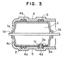
- motor 1 comprises a motor barrel 1a, a motor cover 1b and a motor shaft (a rotational shaft) 1d.
- Motor barrel 1a has a cylindrical shape and is formed as a shape having a bottom. A hole through which motor shaft 1d extends is provided on the bottom of motor barrel 1a at a central position.
- Motor cover 1b is formed as a disc-like shape, and at its central portion, a hole through which motor shaft 1d extends is provided.
- two ring-like rubber vibration isolators 2 and 3 are disposed on the outer surface of cylindrical motor barrel 1a of motor 1 in the axial direction of motor 1. Rubber vibration isolators 2 and 3 are interposed between motor barrel 1a and upper casing 4 and lower casing 5, and they function to suppress the vibration.
- ring-like rubber vibration isolators 2 and 3 are disposed on motor barrel 1a in the axial direction of motor 1 at right and left positions in the figure.
- the inner diameters of rubber vibration isolators 2 and 3 are set smaller than the outer diameter of motor barrel 1a, and therefore, the rubber vibration isolators 2 and 3 are disposed at a high accuracy without generation of a clearance.
- a plurality of ring-like casing grooves 4a extending in the circumferential direction are provided on the inner surfaces of upper casing 4 and lower casing 5 in correspondence with the attachment portions of rubber vibration isolators 2 and 3.
- rubber vibration isolators 2 and 3 are disposed in the respective casing grooves 4a.
- a casing rib 4b projecting toward rotational shaft 1 d and extending in the circumferential direction is provided in each casing groove 4a.
- Motor 1 and barrel 1a are disposed between upper casing 4 and lower casing 5, and as shown in Fig.
- lower casing 5 has a casing projection 4d.
- Casing projection 4d has a columnar shape and it is projected radially toward rotational shaft 1d from the inner surface of lower casing 5, in this embodiment, from the inner surface of the bottom of casing groove 4a.
- barrel hole 1c (through hole) is provided on barrel 1a of motor 1.
- Rubber projection 3a is provided on rubber vibration isolator 3, and the rubber projection 3a is inserted and fitted into barrel hole 1c.
- a through hole 3b is provided in rubber projection 3a.
- Casing projection 4d of lower casing 5 is inserted into through hole 3b of rubber vibration isolator 3 and at the same time, inserted into barrel hole 1c of barrel 1a of motor 1, as shown in Fig. 3.
- casing projection 4d restricts the movement of motor 1 in the rotational direction.
- casing stopper portion 4c is provided, and both casing stopper portions 4c restrict the movement of motor 1 in the axial direction.
- cylindrical barrel 1a of motor 1 is fixed directly by upper casing 4 and lower casing 5 and rubber vibration isolators 2 and 3 are interposed therebetween, the stability in fixing can be increased. Further, since motor 1 is completely floated from the pair of casings by the rubber vibration isolators, a vibration, etc. can be absorbed well and the vibration proof property can be improved. Moreover, because the structure for nipping the motor between the pair of casings is employed, the motor can be easily fixed.
- casing ribs 4b are provided on casings 4 and 5, when the casings 4 and 5 are fastened by casing bolts and nuts, rubber vibration isolators 2 and 3 can be easily compressed with a small fastening force, thereby improving the properties in attachment and fixing of the rubber vibration isolators 2 and 3.
- casing projection 4d is inserted into barrel hole 1c provided on barrel 1a of motor 1 via through hole 3b of rubber vibration isolator 3, the movement of motor 1 in the rotational direction can be regulated. Further, the movement of motor 1 in the axial direction can be regulated by the casing stopper portions provided on one side in the axial direction of the casings.
- the motor 1 and barrel 1a can be surely positioned in a proper position not only in the axial direction but also in the circumferential direction. Therefore, at the time of positioning, it is not necessary to use an exclusive jig, and the cost for assembly can be reduced.
Landscapes
- Engineering & Computer Science (AREA)
- Power Engineering (AREA)
- Mechanical Engineering (AREA)
- General Engineering & Computer Science (AREA)
- Motor Or Generator Frames (AREA)
- Air-Conditioning For Vehicles (AREA)
- Connection Of Motors, Electrical Generators, Mechanical Devices, And The Like (AREA)
- Vibration Prevention Devices (AREA)
Claims (4)
- Haltestruktur für einen Gebläsemotor, der einen Motor (1) und zwei Lüfterräder (6R, 6L), von denen jedes an ein jeweiliges Ende einer Rotationswelle des Motors befestigt ist, aufweist, wobei die Struktur einen ringartigen Gummivibrationsisolator (3) aufweist, der derart angeordnet ist, dass er im Einsatz auf einer zylindrischen Trommel (1b) des Motors angeordnet ist, und ein Paar von Gehäusen (4, 5) zum Enthalten der Trommel (1b) im Einsatz aufweist, und die derart angeordnet sind, dass der Motor durch Eingriff der Trommel (1b) über den Gummivibrationsisolator mit dem Paar von Gehäusen (4, 5) gehalten und befestigt wird, dadurch gekennzeichnet, dass der Gummivibrationsisolator (3) einen Gummivorsprung (3a) aufweist, der auf diesem an einer Position, welche im Einsatz der Position eines Durchgangsloches (1c) in der Trommel (1b) entspricht, vorgesehen ist, wobei der Gummivorsprung (3a) derart angeordnet ist, um in das Trommedurchgangsloch eingeführt zu werden, und dass ein Gehäusevorsprung (4d) auf mindestens einem Gehäuse, das den Gummivibrationsisolator (3) hält, an einer Position, die der Position des Gummivorsprunges (3a) entspricht, vorgesehen ist, wobei der Gehäusevorsprung (4d) derart angeordnet ist, um in ein Durchgangsloch (3b) des Gummivorsprunges (3a) eingeführt zu werden.
- Haltestruktur für einen Gebläsemotor (1) gemäß Anspruch 1, wobei eine Mehrzahl von Gummivibrationsisolatoren (2, 3) zwischen der Trommel (1a) und den Gehäusen (4, 5) in einer axialen Richtung des Motors vorgesehen sind und im Einsatz mit der Trommel und den Gehäusen im Eingriff stehen.
- Haltestruktur für einen Gebläsemotor gemäß Anspruch 1, wobei das Paar von Gehäusen (4, 5) eine Gehäuserille (4a), die sich in einer Umfangsrichtung erstreckt, und eine Gehäuserippe, die sich in der Umfangsrichtung erstreckt und in der Gehäuserille (4a) vorgesehen ist, aufweist, wobei im Einsatz der Gummivibrationsisolator (2) in der Gehäuserille angeordnet ist und die Gehäuserippe den Gummivibrationsisolator 2 zusammendrückt, wenn das Paar von Gehäusen aneinander gezogen wird.
- Haltestruktur für einen Gebläsemotor gemäß Anspruch 1, wobei jedes von dem Paar von Gehäusen (4, 5) einen Gehäusestopperabschnitt auf einer Seite in einer axialen Richtung des Motors (1) aufweist, um im Einsatz eine axiale Bewegung des Motors zu begrenzen.
Applications Claiming Priority (2)
| Application Number | Priority Date | Filing Date | Title |
|---|---|---|---|
| JP2003053054A JP4128889B2 (ja) | 2003-02-28 | 2003-02-28 | ブロワモータ支持構造 |
| JP2003053054 | 2003-02-28 |
Publications (3)
| Publication Number | Publication Date |
|---|---|
| EP1453181A2 EP1453181A2 (de) | 2004-09-01 |
| EP1453181A3 EP1453181A3 (de) | 2005-04-27 |
| EP1453181B1 true EP1453181B1 (de) | 2007-05-09 |
Family
ID=32767833
Family Applications (1)
| Application Number | Title | Priority Date | Filing Date |
|---|---|---|---|
| EP20040250875 Expired - Lifetime EP1453181B1 (de) | 2003-02-28 | 2004-02-18 | Haltevorrichtung für einen Lüftermotor |
Country Status (4)
| Country | Link |
|---|---|
| EP (1) | EP1453181B1 (de) |
| JP (1) | JP4128889B2 (de) |
| CN (1) | CN100344046C (de) |
| DE (1) | DE602004006325T2 (de) |
Cited By (1)
| Publication number | Priority date | Publication date | Assignee | Title |
|---|---|---|---|---|
| DE102007039814B4 (de) * | 2007-08-23 | 2025-05-08 | Valeo Klimasysteme Gmbh | Befestigungsvorrichtung für Gebläsemotor sowie Fahrzeuggebläse |
Families Citing this family (14)
| Publication number | Priority date | Publication date | Assignee | Title |
|---|---|---|---|---|
| US20040113339A1 (en) | 2002-12-17 | 2004-06-17 | Masterson Peter A. | Elastomeric pin isolator |
| GB2426286B (en) * | 2005-05-12 | 2010-11-10 | Nuaire Ltd | Fan enclosure |
| GB2468778A (en) * | 2005-05-12 | 2010-09-22 | Nuaire Ltd | An enclosure for a fan |
| EP1852957A3 (de) * | 2006-05-02 | 2009-03-11 | NSK Ltd. | Motor einer Servolenkung |
| DE102006048526A1 (de) * | 2006-10-13 | 2008-04-17 | Zf Lenksysteme Gmbh | Elektromotor zur Servounterstützung eines Lenksystems |
| DE102011107634A1 (de) * | 2011-06-30 | 2013-01-03 | Kiekert Aktiengesellschaft | Stelleinheit für kraftfahrzeugtechnische Anwendungen |
| DE102013103177A1 (de) * | 2013-03-28 | 2014-10-02 | Rieter Ingolstadt Gmbh | Antriebsanordnung einer Spinnereivorbereitungsmaschine |
| CN103490537A (zh) * | 2013-09-30 | 2014-01-01 | 苏州双航机电有限公司 | 汽车空调蒸发风机 |
| DE112015003037B4 (de) | 2014-06-27 | 2023-05-04 | Brose Fahrzeugteile SE & Co. Kommanditgesellschaft, Würzburg | Vorrichtung zur schwingungsentkoppelten Motorhalterung |
| CN105048688A (zh) * | 2015-08-31 | 2015-11-11 | 江苏凯德电控科技有限公司 | 电机的盖板与外壳装配结构 |
| GB2553507B (en) * | 2016-08-30 | 2019-11-27 | Dyson Technology Ltd | A handheld appliance |
| CN109873523A (zh) * | 2019-04-25 | 2019-06-11 | 广东工业大学 | 一种防共振电机 |
| FR3102516B1 (fr) * | 2019-10-25 | 2022-04-08 | Psa Automobiles Sa | Support de fixation notamment pour pompe à eau électrique de véhicule |
| CN112600319B (zh) * | 2020-11-24 | 2022-03-08 | 武汉船用电力推进装置研究所(中国船舶重工集团公司第七一二研究所) | 一种电机定子 |
Family Cites Families (5)
| Publication number | Priority date | Publication date | Assignee | Title |
|---|---|---|---|---|
| US282849A (en) * | 1883-08-07 | Fruit-jar | ||
| GB434758A (en) * | 1934-09-20 | 1935-09-09 | Paul Linke | Improvements in the mounting of high speed machines within a casing |
| GB433850A (en) * | 1934-10-11 | 1935-08-21 | Baumgarten G M B H | Electric vacuum cleaner |
| DE10002231A1 (de) * | 2000-01-20 | 2001-08-02 | Bosch Gmbh Robert | Gebläsemotor |
| JP3682397B2 (ja) * | 2000-02-28 | 2005-08-10 | 株式会社東芝 | ファンモータ |
-
2003
- 2003-02-28 JP JP2003053054A patent/JP4128889B2/ja not_active Expired - Lifetime
-
2004
- 2004-02-18 EP EP20040250875 patent/EP1453181B1/de not_active Expired - Lifetime
- 2004-02-18 DE DE602004006325T patent/DE602004006325T2/de not_active Expired - Lifetime
- 2004-02-27 CN CNB2004100082417A patent/CN100344046C/zh not_active Expired - Fee Related
Cited By (1)
| Publication number | Priority date | Publication date | Assignee | Title |
|---|---|---|---|---|
| DE102007039814B4 (de) * | 2007-08-23 | 2025-05-08 | Valeo Klimasysteme Gmbh | Befestigungsvorrichtung für Gebläsemotor sowie Fahrzeuggebläse |
Also Published As
| Publication number | Publication date |
|---|---|
| DE602004006325T2 (de) | 2008-01-10 |
| CN100344046C (zh) | 2007-10-17 |
| CN1531168A (zh) | 2004-09-22 |
| DE602004006325D1 (de) | 2007-06-21 |
| EP1453181A3 (de) | 2005-04-27 |
| EP1453181A2 (de) | 2004-09-01 |
| JP4128889B2 (ja) | 2008-07-30 |
| JP2004262286A (ja) | 2004-09-24 |
Similar Documents
| Publication | Publication Date | Title |
|---|---|---|
| EP1453181A2 (de) | Haltevorrichtung für einen Lüftermotor | |
| KR101873455B1 (ko) | 블로워 모터 | |
| US5530304A (en) | Miniature motor and fan using the same | |
| US7166940B2 (en) | External rotor motor | |
| US12129855B2 (en) | Sound absorbing cover and vibration insulating support for an electric compressor | |
| EP0339682A2 (de) | Lagerungsmechanismus für den Kompressor einer Fahrzeugklimaanlage | |
| WO2004061326A1 (en) | Elastomeric pin isolator | |
| US20210356014A1 (en) | Elastomer Bearing for Attaching an Assembly in a Vehicle | |
| US5145330A (en) | Compressor housing having a structure for preventing the slippage of vibroisolating members | |
| US20080230676A1 (en) | Rubber Mounting, in Particular for a Motor-Driven Pump Unit of a Power Steering System | |
| US20020139630A1 (en) | Torsional vibration damper | |
| JP2015089314A (ja) | 回転電機 | |
| US7175398B2 (en) | Integrally molded sound housing for blower motor | |
| CN110890808A (zh) | 马达隔离器 | |
| US20060276122A1 (en) | Electric fan | |
| CN111788397A (zh) | 真空泵及真空泵用风门 | |
| US6547208B2 (en) | Motor mounting assembly | |
| JPH0738786U (ja) | 防振装置 | |
| JP2002120735A (ja) | 舵取り装置の取付構造 | |
| WO2018225636A1 (ja) | 緩衝部材および緩衝部材を備えた送風装置 | |
| JP2005147226A (ja) | 減衰機能付き締結部材およびその締結部材を用いた防振装置 | |
| JP3904301B2 (ja) | 動力伝達機構 | |
| JP4493576B2 (ja) | 動力伝達装置 | |
| JP4304387B2 (ja) | 電動機の回転子 | |
| JP2004304857A (ja) | モータ取付構造 |
Legal Events
| Date | Code | Title | Description |
|---|---|---|---|
| PUAI | Public reference made under article 153(3) epc to a published international application that has entered the european phase |
Free format text: ORIGINAL CODE: 0009012 |
|
| AK | Designated contracting states |
Kind code of ref document: A2 Designated state(s): AT BE BG CH CY CZ DE DK EE ES FI FR GB GR HU IE IT LI LU MC NL PT RO SE SI SK TR |
|
| AX | Request for extension of the european patent |
Extension state: AL LT LV MK |
|
| PUAL | Search report despatched |
Free format text: ORIGINAL CODE: 0009013 |
|
| AK | Designated contracting states |
Kind code of ref document: A3 Designated state(s): AT BE BG CH CY CZ DE DK EE ES FI FR GB GR HU IE IT LI LU MC NL PT RO SE SI SK TR |
|
| AX | Request for extension of the european patent |
Extension state: AL LT LV MK |
|
| RIC1 | Information provided on ipc code assigned before grant |
Ipc: 7F 16F 15/08 B Ipc: 7H 02K 5/24 B Ipc: 7H 02K 5/04 A |
|
| 17P | Request for examination filed |
Effective date: 20051014 |
|
| AKX | Designation fees paid |
Designated state(s): DE FR IT |
|
| GRAP | Despatch of communication of intention to grant a patent |
Free format text: ORIGINAL CODE: EPIDOSNIGR1 |
|
| GRAS | Grant fee paid |
Free format text: ORIGINAL CODE: EPIDOSNIGR3 |
|
| GRAA | (expected) grant |
Free format text: ORIGINAL CODE: 0009210 |
|
| AK | Designated contracting states |
Kind code of ref document: B1 Designated state(s): DE FR IT |
|
| REF | Corresponds to: |
Ref document number: 602004006325 Country of ref document: DE Date of ref document: 20070621 Kind code of ref document: P |
|
| ET | Fr: translation filed | ||
| PLBE | No opposition filed within time limit |
Free format text: ORIGINAL CODE: 0009261 |
|
| STAA | Information on the status of an ep patent application or granted ep patent |
Free format text: STATUS: NO OPPOSITION FILED WITHIN TIME LIMIT |
|
| 26N | No opposition filed |
Effective date: 20080212 |
|
| PGFP | Annual fee paid to national office [announced via postgrant information from national office to epo] |
Ref country code: IT Payment date: 20120216 Year of fee payment: 9 |
|
| PGFP | Annual fee paid to national office [announced via postgrant information from national office to epo] |
Ref country code: DE Payment date: 20130228 Year of fee payment: 10 Ref country code: FR Payment date: 20130218 Year of fee payment: 10 |
|
| REG | Reference to a national code |
Ref country code: DE Ref legal event code: R119 Ref document number: 602004006325 Country of ref document: DE |
|
| REG | Reference to a national code |
Ref country code: FR Ref legal event code: ST Effective date: 20141031 |
|
| REG | Reference to a national code |
Ref country code: DE Ref legal event code: R119 Ref document number: 602004006325 Country of ref document: DE Effective date: 20140902 |
|
| PG25 | Lapsed in a contracting state [announced via postgrant information from national office to epo] |
Ref country code: FR Free format text: LAPSE BECAUSE OF NON-PAYMENT OF DUE FEES Effective date: 20140228 Ref country code: DE Free format text: LAPSE BECAUSE OF NON-PAYMENT OF DUE FEES Effective date: 20140902 |
|
| PG25 | Lapsed in a contracting state [announced via postgrant information from national office to epo] |
Ref country code: IT Free format text: LAPSE BECAUSE OF NON-PAYMENT OF DUE FEES Effective date: 20140218 |