EP1453341A2 - Paketdatenfunkkommunikationssystem, -verfahren, Basisstation und Mobilstation - Google Patents
Paketdatenfunkkommunikationssystem, -verfahren, Basisstation und Mobilstation Download PDFInfo
- Publication number
- EP1453341A2 EP1453341A2 EP04004199A EP04004199A EP1453341A2 EP 1453341 A2 EP1453341 A2 EP 1453341A2 EP 04004199 A EP04004199 A EP 04004199A EP 04004199 A EP04004199 A EP 04004199A EP 1453341 A2 EP1453341 A2 EP 1453341A2
- Authority
- EP
- European Patent Office
- Prior art keywords
- interference amount
- adjacent cell
- packet communication
- base station
- radio
- Prior art date
- Legal status (The legal status is an assumption and is not a legal conclusion. Google has not performed a legal analysis and makes no representation as to the accuracy of the status listed.)
- Granted
Links
Images


Classifications
-
- H—ELECTRICITY
- H04—ELECTRIC COMMUNICATION TECHNIQUE
- H04W—WIRELESS COMMUNICATION NETWORKS
- H04W72/00—Local resource management
- H04W72/02—Selection of wireless resources by user or terminal
-
- H—ELECTRICITY
- H04—ELECTRIC COMMUNICATION TECHNIQUE
- H04W—WIRELESS COMMUNICATION NETWORKS
- H04W24/00—Supervisory, monitoring or testing arrangements
-
- H—ELECTRICITY
- H04—ELECTRIC COMMUNICATION TECHNIQUE
- H04W—WIRELESS COMMUNICATION NETWORKS
- H04W88/00—Devices specially adapted for wireless communication networks, e.g. terminals, base stations or access point devices
- H04W88/08—Access point devices
Definitions
- the present invention relates to a radio packet communication system and a radio packet communication method for performing radio packet communication between a base station and a mobile station.
- the present invention also relates to a base station and a mobile station which are used in the system and the method.
- each of base and mobile stations estimates a condition of a propagation path in a transmission frequency toward itself by using a signal received by itself, and determines a transmission-modulation mode for each other.
- each of the base and mobile stations estimates a condition of a propagation path in a transmission frequency toward itself by use of a received signal included in a time slot in a transmission frame, and then determines the transmission-modulation mode which can transmit the largest quantity of information within a given transmission error rate under the estimated condition of the transmission path. Subsequently, each of the base and mobile stations transmits data including information indicating the determined transmission-modulation mode by use of a time slot in a subsequent transmission frame. Then, each of the base and mobile stations, which has received the transmitted data, transmits a subsequent transmission frame by the transmission-modulation mode included in the data.
- the base station or the mobile station transmits the transmission frames with the maximum transmission power by use of the transmission-modulation mode which can transmit the largest quantity of information within the given transmission error rate under the estimated condition of each transmission path. Therefore, the base station or the mobile station can achieve the maximum communication speed. That is, even when the condition of the propagation path changes, the base station or the mobile station modifies the transmission-modulation mode, but does not modify the transmission power.
- a basic concept of the radio packet communication system is to reduce the number of packets to be transmitted in the same time slot or the number of mobile stations transmitting packets in the same time slot, so as to enable each packet or each mobile station to use many radio resources instantaneously, to complete transmission as soon as possible, and to offer the used radio resources to a subsequent packet or a different mobile station.
- each of the base and mobile stations detects a signal to interference power ratio (SIR) which is an interference amount in a received signal included in a transmission frame, then selects a digital modulation mode out of a plurality of digital modulation modes which can transmit the largest quantity of information within a given transmission error rate based on the detected interference amount, and then transmits data including information indicating the selected digital modulation mode to each other.
- SIR signal to interference power ratio
- the base station or the mobile station can change the digital modulation mode adaptively.
- This radio packet communication system tracks a variation in the interference amount attributable to a traffic variation, phasing, or the like, by detecting the interference amount at the base station or the mobile station, and uses the digital modulation mode which can transmit the largest quantity of information in accordance with the interference at that moment. In this way, the radio packet communication system can use the frequency effectively.
- the radio packet communication system when many mobile stations are located close to a cell border, the interference amount with an adjacent cell fluctuates instantaneously and significantly because of an instantaneous increase in the traffic in the cell. Accordingly, there has been a problem in that the radio packet communication system has a risk of an increase in occurrence of a communication error in the adjacent cell.
- the interference amount with the adjacent cell fluctuates instantaneously and significantly because of a variation in distance between the base station and the mobile station. Accordingly, there has been a problem in that a possibility of occurrence of a communication error in the adjacent cell increases.
- a first aspect of the present invention is summarized as a radio packet communication system for performing radio packet communication between a base station and a mobile station.
- the base station includes an adjacent cell interference amount calculator and an adjacent cell interference amount notifier.
- the adjacent cell interference amount calculator is configured to calculate an adjacent cell interference amount caused by an adjacent cell which is adjacent to an original cell managed by the base station.
- the adjacent cell interference amount notifier is configured to notify the mobile station of the adjacent cell interference amount.
- the mobile station includes a plurality of radio resource associators, a selector, a propagation loss calculator, and a radio resource assigner.
- the radio resource associators are configured to associate a radio resource with a propagation loss in the radio packet communication.
- the selector is configured to select a radio resource associator in accordance with the adjacent cell interference amount notified by the base station.
- the propagation loss calculator is configured to calculate a propagation loss in the radio packet communication.
- the radio resource assigner is configured to assign the radio resource associated with the calculated propagation loss to the radio packet communication, in accordance with the selected radio resource associator.
- a second aspect of the present invention is summarized as a radio packet communication method for performing radio packet communication between a base station and a mobile station.
- the mobile station has a plurality of radio resource associators configured to associate a radio resource with a propagation loss in the radio packet communication.
- the base station calculates an adj acent interference amount caused by an adj acent cell which is adjacent to an original cell managed by the base station.
- the base station notifies the mobile station of the adjacent cell interference amount.
- the mobile station selects a radio resource associator in accordance with the adjacent cell interference amount notified by the base station.
- the mobile station calculates a propagation loss in the radio packet communication.
- the mobile station assigns the radio resource associated with the calculated propagation loss to the radio packet communication, in accordance with the selected radio resource associator.
- a third aspect of the present invention is summarized as a base station for performing radio packet communication with a mobile station.
- the base station includes a plurality of radio resource associators, an adjacent cell interference amount calculator, a selector, a propagation loss calculator, and a radio resource assigner.
- the radio resource associators are configured to associate a radio resource with a propagation loss in the radio packet communication.
- the adjacent cell interference amount calculator is configured to calculate an adjacent cell interference amount caused by an adjacent cell which is adjacent to an original cell managed by the base station.
- the selector is configured to select a radio resource associator in accordance with the adjacent cell interference amount.
- the propagation loss calculator is configured to calculate a propagation loss in the radio packet communication.
- the radio resource assigner is configured to assign the radio resource associated with the calculated propagation loss to the radio packet communication, in accordance with the selected radio resource associator.
- a fourth aspect of the present invention is summarized as a base station for performing radio packet communication with a mobile station.
- the base station includes an adjacent cell interference amount calculator and an adjacent cell interference amount notifier.
- the adjacent cell interference amount calculator is configured to calculate an adjacent cell interference amount caused by an adj acent cell which is adj acent to an original cell managed by the base station.
- the adjacent cell interference amount notifier is configured to notify the mobile station of the adjacent cell interference amount.
- a fifth aspect of the present invention is summarized as a mobile station for performing radio packet communication with a base station.
- the mobile station includes a plurality of radio resource associators, a selector, a propagation loss calculator, and a radio resource assigner.
- the radio resource associators are configured to associate a radio resource with a propagation loss in the radio packet communication.
- the selector is configured to select a radio resource associator in accordance with an adjacent cell interference amount notified by the base station.
- the adjacent cell interference amount are caused by an adjacent cell which is adjacent to an original cell managed by the base station.
- the propagation loss calculator is configured to calculate a propagation loss in the radio packet communication.
- the radio resource assigner is configured to assign the radio resource associated with the calculated propagation loss to the radio packet communication, in accordance with the selected radio resource associator.
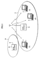
- Fig. 1 is an overall block diagram of a radio packet communication system according to a first embodiment of the present invention.
- Fig. 2 is a functional block diagram of a mobile station in the radio packet communication system according to the first embodiment of the present invention.
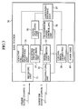
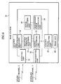
- Fig. 3 is a functional block diagram of a base station in the radio packet communication system according to the first embodiment of the present invention.
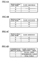
- Figs. 4A to 4D show examples of tables to be managed by the base station in the radio packet communication system according to the first embodiment of the present invention.
- Fig. 5 is a view for explaining an operation to allocate radio resources. by the base station in the radio packet communication system according to the first embodiment of the present invention.
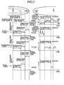
- Fig. 6 is a flowchart showing the operation to allocate the radio resources by the base station in the radio packet communication system according to the first embodiment of the present invention.
- Fig. 7 is a functional block diagram of a mobile station in a radio packet communication system according to a second embodiment of the present invention.
- Fig. 8 is a functional block diagram of a base station in the radio packet communication system according to the second embodiment of the present invention.
- Fig. 9 is a flowchart showing an operation to allocate radio resources by the base station in the radio packet communication system according to the second embodiment of the present invention.
- a radio packet communication system of this embodiment is configured to perform radio packet communication of the CDMA method between a base station 30 and a plurality of mobile stations 10a to 10c.
- packet signals from the plurality of mobile stations 10a to 10c located in a cell (a radio zone) A formed by the base station 30 are transmitted to the base station 30 on a common uplink radio channel.
- the mobile station 10 includes a receiving unit 11, a signal converting unit 12, a signal analyzing unit 13, a transmission power controlling unit 14, a transmitting unit 15, a packet generating unit 16, a control signal generating unit 17, and a timer unit 18.
- the receiving unit 11 is a circuit configured to receive control signals and packet signals transmitted from the base station 30 through a downlink radio channel 3.
- the control signals include an assignment signal, a synchronization signal, a confirmation signal, and a pilot signal, for example.
- the receiving unit 11 transmits the received control signal to the signal converting unit 12.
- the signal converting unit 12 is a circuit configured to perform given signal conversion. Specifically, the signal converting unit 12 subjects a packet from the packet generating unit 16, or a control signal from the control signal generating unit 17 such as a reservation signal or a pilot signal, to an encoding process, a spreading process, and a modulating process, and then outputs the packet or the control signal to the transmitting unit 15.
- the signal converting unit 12 subjects a control signal from the receiving unit 11 such as an assignment signal, or a packet signal, to a demodulating process, a despreading process, and a decoding process, and then outputs the control signal or the packet signal to the signal analyzing unit 13.
- a control signal from the receiving unit 11 such as an assignment signal, or a packet signal
- the signal converting unit 12 may be configured to subject the packet from the packet generating unit 16 to the spreading process and the modulating process by use of a spreading code and a modulation mode which are notified by an enabling signal from the signal analyzing unit 13, and to output the packet signal subjected to the spreading process and the modulating process to the transmitting unit 15 based on timing information which is notified by the enabling signal.
- the signal analyzing unit 13 is a circuit configured to analyze the control signal and the packet signal from the signal converting unit 12, and to output an analysis result to the respective units in response to the type of the signal.
- the signal analyzing unit 13 analyzes the assignment signal from the base station 30, and thereby outputs the spreading code, the timing information, and the like, which are assigned to the packet signal transmitted from the base station 30, to the signal converting unit 12.
- the signal analyzing unit 13 analyzes the control signal from the base station 30, and thereby outputs information concerning the transmission power, which is assigned to the packet signal transmitted from the base station 30, to the transmission power controlling unit 14.
- the signal analyzing unit 13 analyzes the synchronization signal or the pilot signal from the base station 30, and thereby outputs synchronization information to the control signal generating unit 17.
- the signal analyzing unit 13 analyzes the packet signal from the base station 30, and thereby outputs output data.
- the transmission power controlling unit 14 is a circuit configured to control the transmission power of a signal to be transmitted through the transmitting unit 15.
- the transmission power controlling unit 14 outputs information concerning the transmission power of the reservation signal and information concerning the maximum transmission power of the mobile station 10, to the control signal generating unit 17.
- the transmitting unit 15 is a circuit configured to transmit the control signal such as the reservation signal or the pilot signal, and the packet signal which have been converted by the signal converting unit 12, to the base station 30 with the transmission power controlled by the transmission power controlling unit 14 through an uplink radio channel 2.
- the packet generating unit 16 is a circuit configured to generate packets based on input data. Specifically, the packet generating unit 16 generates a plurality of packets by dividing input data having at least a given length. The packet generating unit 16 outputs the generated packets to the signal converting unit 12.
- the control signal generating unit 17 is a circuit configured to generate various control signals such as the reservation signal, the synchronization signal or the pilot signal.
- the control signal generating unit 17 outputs the control signals thus generated to the signal converting unit 12.
- control signal generating unit 17 can generate the reservation signal which includes the information concerning the transmission power of the reservation signal and the information concerning the maximum transmission power of the mobile station 10 from the transmission power controlling unit 14, and the like.
- control signal generating unit 17 may be configured to generate the control signals such as the synchronization signal or the reservation signal periodically in response to an instruction from the timer unit 18.
- control signal generating unit 17 can generate the reservation signal for acquiring the spreading code, the modulation mode, the transmission power, the timing information, and the like, from the base station 30 prior to transmission of the packet signal.
- control signal generating unit 17 can generate the reservation signal which includes information concerning an amount (or the number) of subsequent packets and the current transmission power.
- the base station 30 includes a receiving unit 31, a transmitting unit 32, a signal converting unit 33, an adjacent cell interference measuring unit 34, a reception strength measuring unit 35, a signal analyzing unit 36, an assignment deciding unit 37, a transmission power controlling unit 38, a control signal generating unit 39, and a timer unit 40.
- the receiving unit 31 is a circuit configured to receive the control signals such as the reservation signal or the pilot signal, and the packet signals, through the uplink radio channel 2.
- the receiving unit 31 outputs the received signals to the signal converting unit 33 through the adjacent cell interference measuring unit 34 and the reception strength measuring unit 35.
- the transmitting unit 32 is a circuit configured to transmit the control signal such as the assignment signal, the synchronization signal, the confirmation signal or the pilot signal, and the packet signal, through the downlink radio channel 3.
- the transmitting unit 32 transmits the control signal and the packet signal from the signal converting unit 33 with the transmission power controlled by the transmission power controlling unit 38.
- the signal converting unit 33 is a circuit configured to perform given signal conversion.
- the signal converting unit 33 subjects a control signal from the control signal generating unit 39 to the encoding process, the spreading process, and the modulating process, and then outputs the control signal to the transmitting unit 32.
- the signal converting unit 33 subjects a control signal such as the assignment signal or the packet signal from the reception strength measuring unit 35, to the demodulating process, the despreading process, and the decoding process, and then outputs the control signal or the packet signal to the signal analyzing unit 36.
- a control signal such as the assignment signal or the packet signal from the reception strength measuring unit 35
- the adjacent cell interference measuring unit 34 constitutes an adjacent cell interference amount calculator configured to calculate an adjacent cell interference amount caused by an adjacent cell B, which is adj acent to the original cell A to be managed by the base station 30.
- the adjacent cell interference measuring unit 34 can calculate a total interference amount based on the signal transmitted from the mobile station 10, and calculate an original cell interference amount in the original cell A based on the received amount of packets (the received packet amount) , and thereby calculate the adjacent cell interference amount caused by the adjacent cell B by use of the total interference amount and the original cell interference amount.
- the adjacent cell interference measuring unit 34 can detect the total interference amount, based on SIR and desired signal received power of the pilot signal transmitted from the mobile station 10.
- the adjacent cell interference measuring unit 34 can estimate the original cell interference amount in the original cell A based on the received amount of packets. Therefore, the adjacent cell interference measuring unit 34 can determine the remaining interference amount obtained by subtracting the original cell interference amount from the total interference amount, as the adjacent cell interference amount.
- the adjacent cell interference measuring unit 34 outputs the calculated adjacent cell interference amount to the assignment deciding unit 37.
- the adjacent cell interference measuring unit 34 may be configured to average the calculated adj acent cell interference amount in a given period, and to output information concerning the averaged adj acent cell interference amount to the assignment deciding unit 37.
- the reception strength measuring unit 35 is a circuit configured to measure reception strength of the reservation signal from the adjacent cell interference measuring unit 34, and to output a measurement result to the signal analyzing unit 36.
- the signal analyzing unit 36 is a circuit configured to analyze the control signals from the signal converting unit 33.
- the signal analyzing unit 36 mainly analyzes the reservation signal or the synchronization signal, and outputs an analysis result to the assignment deciding unit 37 and the transmission power controlling unit 38.
- the signal analyzing unit 36 may be configured to analyzes the reservation signal, and thereby to extract the information concerning the amount of packets and the current transmission power, the information concerning the maximum transmission power of the mobile station 10, or the like, and to output the information to the assignment deciding unit 37.
- the signal analyzing unit 36 constitutes a propagation loss calculator configured to calculate a propagation loss in the radio packet communication with the mobile station 10, based on the information concerning the current transmission power included in the reservation signal and based on the reception strength of the reservation signal from the reception strength measuring unit 35.
- the signal analyzing unit 36 outputs the information concerning the calculated propagation loss to the assignment deciding unit 37 and the transmission power controlling unit 38.
- the assignment deciding unit 37 includes a plurality of radio resources assignment tables (radio resource associators) configured to associate the radio resources with the propagation loss in the radio packet communication the mobile station 10.
- radio resources assignment tables radio resource associators
- Figs. 4A to 4C show examples of the radio resources assignment tables for the original cell A. As shown in Figs. 4A to 4C, the radio resources assignment tables are configured to associate "propagation loss ranks" with the "radio resources".
- the "propagation loss rank” is defined by the propagation loss between the mobile station 10 and the base station 30 in the original cell A.
- the propagation loss rank assigned to the area having the smallest propagation loss i.e. the area having the shortest distance from the base station 30 is defined as "A”.
- the propagation loss rank assigned to the area having the second smallest propagation loss, i.e. the area having the second shortest distance from the base station 30 is defined as "B”.
- the propagation loss rank assigned to the area having the largest propagation loss, i.e. the area having the longest distance from the base station 30 is defined as "C”.
- radio resources indicate radio resources to be assigned to the respective mobile stations located in the areas corresponding to the above-described propagation loss ranks A to C.
- the "radio resources" indicates at least one of spreading ratio, the number of spreading codes, the modulation mode, a coding rate of an error correction code, and the transmission power.
- An initial table shown in Fig. 4A is set as follows.
- upper limits of transmission rates to be assigned to the respective areas corresponding to the propagation loss ranks A to C are determined based on the maximum transmission power of the mobile station 10 and the highest propagation losses in the respective areas corresponding to the propagation loss ranks A to C.
- radio resources a1 to c1 to be associated with the respective propagation loss ranks A to C are determined.
- a final table shown in Fig. 4C is set as follows.
- the minimum transmission rates to be guaranteed by the respective areas corresponding to the propagation loss ranks A to C are determined.
- radio resources a3 to c3 to be associated with the respective propagation loss ranks A to C are determined.
- an intermediate table shown in Fig. 4B is set as follows.
- transmission rates between the above-described upper limits of the transmission rates and the above-described minimum transmission rates are determined for the respective areas corresponding to the propagation loss ranks A to C.
- radio resources a2 to c2 to be associated with the respective propagation loss ranks A to C are determined.
- the spreading ratio set as "4" is associated with the propagation loss rank A
- the spreading ratio set as "16” is associated with the propagation loss rank B
- the spreading ratio set as "64" is associated with the propagation loss rank C.
- the spreading ratio set as "4" is associated with the propagation loss rank A
- the spreading ratio set as "16” is associated with the propagation loss rank B
- the spreading ratio set as "128” is associated with the propagation loss rank C.
- the spreading ratio set as "4" is associated with the propagation loss rank A
- the spreading ratio set as "32” is associated with the propagation loss rank B
- the spreading ratio set as "256" is associated with the propagation loss rank C.
- the transmission rate of the mobile station 10 in the propagation loss rank B is set slightly higher than the transmission rate of the mobile station 10 in the propagation loss rank C.
- the transmission rate of the mobile station 10 in the propagation loss rank A is set equal.
- the assignment deciding unit 37 constitutes a selector configured to select a radio resources assignment table (a radio resource associator) in response to the adjacent cell interference amount which is transmitted from the adjacent cell interference measuring unit 34.
- the assignment deciding unit 37 makes reference to a selection table shown in Fig. 4D, and selects the specific radio resources assignment table in response to the adjacent cell interference amount.
- Fig. 4D shows an example of the selection table for the original cell A. As shown in Fig. 4D, the selection table is configured to associate "interference amount rank" with "radio resources assignment tables".
- the "interference amount rank" is defined by the interference amount caused by the adjacent cell B.
- the interference amount rank is defined as "1".
- the interference amount rank is defined as "2".
- the interference amount rank is defined as "3".
- the "radio resources assignment table” indicates a radio resources assignment table to be selected by the assignment deciding unit 37 in the case of corresponding to the above-described interference amount ranks "1" to "3" respectively.
- the selection table is configured such that the initial table for setting the fastest transmission rate is selected when the interference amount caused by the adjacent cell B is small (in the case of the interference amount rank "1").
- the selection table is configured such that the intermediate table is selected when the interference amount caused by the adjacent cell B is large (in the case of the interference amount rank "2").
- the selection table is configured such that the final table for setting the slowest transmission rate is selected when the interference amount caused by the adjacent cell B is extremely large (in the case of the interference amount rank "3").
- the radio resources are assigned to a mobile station located in the vicinity of the cell border (the mobile station in the propagation loss rank C) so as to slow down transmission rate thereof when the interference amount caused by the adj acent cell B is large (i.e. when a traffic amount of the adjacent cell B is large). Therefore, it is possible to stabilize or reduce the interference amount from the original cell A to the adj acent cell B.
- the mobile station located in the vicinity of the cell border (the mobile station in the propagation loss rank C) is changed from high-speed intermittent transmission to continuous low-speed transmission. Therefore, the interference amount with the adjacent cell B (the interference amount from the original cell A to the adjacent cell B) is averaged.
- a variation in the interference amount with the adjacent cell B is moderated by a statistical multiplexing effect attributable to an increase in the number of mobile stations which are simultaneously transmittable.
- the transmission rate of the mobile station located in the vicinity of the cell border (the mobile station in the propagation loss rank C) is reduced. Therefore, the interference amount with the adjacent cell B is reduced.
- the interference amount caused by the adjacent cell B is increased, it is possible to reduce the interference amount with the adjacent cell B and to achieve effective use of the radio resources in a multi-cell environment, by assigning the radio resources (such as the spreading ratio) to the mobile station located in the vicinity of the cell border so as to slow down the transmission rate thereof, and by reducing the transmission power at the same time. In this way, it is possible to increase the system throughput, and to improve the communication quality.
- the radio resources such as the spreading ratio
- the reason for assigning the radio resources (such as the spreading ratio) to the mobile station so as to slow down the transmission rate as described above, only when the interference amount caused by the adjacent cell B is large (i.e. when the traffic amount of the adjacent cell B is large) is as follows.
- the adjacent call B can perform transmission with a large interference margin, and it is less likely to cause a failure to receive information bits. Accordingly, a desire to exert the maximum communication speed of the mobile station in the original cell A has a priority.
- the interference amount caused by the adjacent cell B is large (i.e. when the traffic amount of the adjacent cell B is large)
- the interference amount caused by the original cell A, which is estimated by the adjacent cell B is smaller than the real amount. Therefore, there is an increasing risk of occurrence of a failure to receive a large amount of information bits at the adjacent cell B.
- the reason for modifying only the transmission rate of the mobile station located in the vicinity of the cell border i.e. the mobile station in the propagation loss rank C is as follows.
- Simultaneous transmission among fewer mobile stations has a smaller ratio between interfered reception power and total reception power, as compared to simultaneous transmission among more mobile stations (8 stations or more, for example) . Accordingly, the simultaneous transmission among fewer mobile stations can achieve higher system throughput.
- the transmission rate of the mobile station located in a central part of the cell i.e. the mobile station in the propagation loss rank A
- the transmission rate of the mobile station located in a central part of the cell i.e. the mobile station in the propagation loss rank A
- the propagation loss rank A which can use the entire radio resources with fewer mobile stations
- an effect to the system throughput is limited even if the number of mobile stations for performing the simultaneous transmission is increased, by reducing the transmission rate of the mobile station located in the vicinity of the cell border (i.e. the mobile station in the propagation loss rank C) which cannot use the entire radio resources in the absence of the large number of mobile stations due to the propagation losses and the like. Accordingly, only the transmission rate of the mobile station located in the vicinity of the cell border is modified.
- the interference amount with the adjacent cell B caused by the mobile station located in the vicinity of the cell border is larger than the interference amount with the adjacent cell B caused by the mobile station located in the central part of the cell, it is effective to stabilize or reduce the interference amount with the adjacent cell B caused by the mobile station located in the vicinity of the cell border.
- the assignment deciding unit 37 constitutes a radio resources assigner configured to make reference to the selected radio resources assignment table, and thereby to assign the radio resources associated with the calculated propagation loss, to the radio packet communication with the mobile station 10.
- the assignment deciding unit 37 can update the radio resources assignment table in response to the adjacent cell interference amount within a given period (such as an average interference amount caused by the adjacent cell) , which is transmitted from the adjacent cell interference measuring unit 34.
- the assignment deciding unit 37 transmits a result of assignment of the radio resources to the control signal generating unit 39.
- the transmission power controlling unit 38 determines the transmission power based on the information concerning the propagation loss from the signal analyzing unit 36, and outputs the transmission power to the transmitting unit 32.
- the control signal generating unit 39 generates an assignment signal, and outputs the assignment signal to the signal converting unit 33.
- the assignment signal is transmitted from the assignment deciding unit 37, and notifies the mobile station 10 of the result of assignment of the radio resources.
- control signal generating unit 39 may be configured to generate the control signals such as the assignment signal, the synchronization signal, the confirmation signal or the pilot signal periodically in response to an instruction from the timer unit 40.
- the reception strength measuring unit 35 of the base station 30 receives the reservation signal transmitted from the mobile station 10, prior to transmission of the packet signal, and measures the reception power (the reception strength) of the reservation signal.
- Step 502 the signal analyzing unit 36 of the base station 30 calculates the propagation loss in the radio packet communication with the mobile station 10, based on the information concerning the current transmission power included in the reservation signal, and based on the reception strength of the reservation signal from the reception strength measuring unit 35.
- Step 503 the adjacent cell interference measuring unit 34 calculates the total interference amount (total interference signal strength) based on the signal transmitted from the mobile station 10.
- the adjacent cell interference measuring unit 34 calculates the interference amount caused by the adjacent cell B, based on the calculated total interference amount (the total interference signal strength) and the interference amount in the original cell A calculated by the received amount of packets.
- Step 505 the assignment deciding unit 37 makes reference to the selection table shown in Fig. 4D, and selects the specific radio resources assignment table in response to the interference amount caused by the adjacent cell B.
- the radio resources assignment table is updated in response to the interference amount caused by the adjacent cell B within a given period (such as several tens of seconds or several minutes).
- the interference amount caused by the adjacent cell B within the given period is calculated by adding the interference amount caused by the adjacent cell B in each time slot.
- Step 506 the assignment deciding unit 37 makes reference to the selected radio resources assignment table, and assigns the radio resources associated with the propagation loss calculated by the adjacent cell interference measuring unit 34, to the radio packet communication with the mobile station 10.
- Step 507 the control signal generating unit 39 generates the assignment signal for notifying the mobile station 10 of the radio resources assigned by the assignment deciding unit 37, and transmits the assignment signal to the mobile station 10 through the signal converting unit 33 and the transmitting unit 32.
- the assignment deciding unit 37 of the base station 30 assigns the radio resources in response to the interference amount caused by the adjacent cell B. Therefore, it is possible to adjust the radio resources to be assigned to the mobile station 10 having the large interference amount with the adjacent cell (such as the mobile station located in the vicinity of the cell border) and the radio resources to be assigned to the mobile station 10 having the small interference amount with the adjacent cell (such as the mobile station located in the central part of the cell). In this way, it is possible to reduce an influence of the variation in the interference amount with the adjacent cell B without reducing the transmission rate of the mobile station located in the central part of the cell.
- the radio packet communication system according the above-described first embodiment is an example of a reservation-type system in which the base station 30 assignes the radio resources to the mobile station 10
- the radio packet communication system according to this embodiment is a non-reservation-type system in which the mobile station 10 assigns the radio resources by itself.
- the configuration of the radio packet communication system according to this embodiment is the same as the configuration of the radio packet communication system according to the above-described first embodiment, except that the reception strength measuring unit 35 and the assignment deciding unit 37 is provided to the mobile station 10 instead of the base station 30.
- the reception strength measuring unit 35 constitutes the propagation loss calculator configured to calculate a propagation loss in the radio packet communication with the base station 30.
- the reception strength measuring unit 35 can calculate the above-described propagation loss by use of reception power of a pilot signal from the base station 30.
- the assignment deciding unit 37 includes the plurality of radio resources assignment tables configured to associate the propagation loss in the radio packet communication, between the base station 30 and the mobile station 10, with the radio resources (see Figs. 4A to 4C).
- the assignment deciding unit 37 constitutes the selector configured to select the specific radio resources assignment table in response to the interference amount caused by the adjacent cell which is notified by the base station 30.
- the assignment deciding unit 37 constitutes the radio resources assigner configured to make reference to the selected radio resources assignment table and thereby to assign the radio resources associated with the calculated propagation loss, to the radio packet communication with the base station 30.
- control signal generating unit 39 of the base station 30 generates control information including the interference amount caused by the adjacent cell B which is calculated by the adjacent cell interference measuring unit 34, and then transmits the control information to the mobile station 10 through the signal converting unit 33 and the transmitting unit 32.
- Step 801 the adjacent cell interference measuring unit 34 of the base station 30 calculates the total interference amount (the total interference signal strength) based on the signal transmitted from the mobile station 10.
- the adjacent cell interference measuring unit 34 calculates the interference amount caused by the adjacent cell B, based on the calculated total interference amount (the total interference signal strength) and the interference amount in the original cell A calculated by the received amount of packets.
- Step 803 the control signal generating unit 39 of the base station 30 generates the control information including the interference amount caused by the adjacent cell B which is calculated by the adjacent cell interference measuring unit 34, and then transmits the control information to the mobile station 10 through the signal converting unit 33 and the transmitting unit 32.
- the reception strength measuring unit 35 of the mobile station 10 receives the pilot signal from the base station 30 in Step 811, and calculates the above-described propagation loss by use of the reception power of the received pilot signal in Step 812.
- Step 813 the assignment deciding unit 37 of the mobile station 10 extracts the interference amount caused by the adjacent cell B included in the control information from the base station 30.
- Step 814 the assignment deciding unit 37 makes reference to the selection table shown in Fig. 4D, and selects the specific radio resources assignment table in response to the extracted interference amount caused by the adjacent cell B.
- the radio resources assignment table is updated in response to the interference amount caused by the adjacent cell B within a given period (such as several tens of seconds or several minutes).
- the interference amount caused by the adjacent cell B within the given period is calculated by adding the interference amount caused by the adjacent cell B in each time slot.
- Step 815 the assignment deciding unit 37 makes reference to the selected radio resources assignment table, and assigns the radio resources associated with the propagation loss calculated by the adjacent cell interference measuring unit 34, to the radio packet communication with the base station 30.
- the assignment deciding unit 37 of the mobile station 10 assigns the radio resources in response to the interference amount caused by the adjacent cell B which is transmitted from the base station 30. Therefore, it is possible to adjust the radio resources to be assigned to the mobile station 10 having the large interference amount with the adjacent cell (such as the mobile station located in the vicinity of the cell border) and the radio resources to be assigned to the mobile station 10 having the small interference amount with the adjacent cell (such as the mobile station located in the central part of the cell). In this way, it is possible to reduce the influence of the variation in the interference amount relative to the adjacent cell B without reducing the transmission rate of the mobile station located in the central part of the cell.
- the radio packet communication system and the radio packet communication method which effectuates stable radio packet communication by moderating the influence of the variation in the interference amount with the adjacent cell B, and the base station and the mobile station which are suitable for use in the foregoing system and method.
Landscapes
- Engineering & Computer Science (AREA)
- Computer Networks & Wireless Communication (AREA)
- Signal Processing (AREA)
- Mobile Radio Communication Systems (AREA)
Applications Claiming Priority (2)
| Application Number | Priority Date | Filing Date | Title |
|---|---|---|---|
| JP2003048035A JP4178055B2 (ja) | 2003-02-25 | 2003-02-25 | 無線パケット通信システム、無線パケット通信方法、基地局及び移動局 |
| JP2003048035 | 2003-02-25 |
Publications (3)
| Publication Number | Publication Date |
|---|---|
| EP1453341A2 true EP1453341A2 (de) | 2004-09-01 |
| EP1453341A3 EP1453341A3 (de) | 2007-10-03 |
| EP1453341B1 EP1453341B1 (de) | 2009-07-15 |
Family
ID=32767738
Family Applications (1)
| Application Number | Title | Priority Date | Filing Date |
|---|---|---|---|
| EP20040004199 Expired - Lifetime EP1453341B1 (de) | 2003-02-25 | 2004-02-25 | Paketdatenfunkkommunikationssystem, -verfahren, Basisstation und Mobilstation |
Country Status (5)
| Country | Link |
|---|---|
| US (1) | US7184709B2 (de) |
| EP (1) | EP1453341B1 (de) |
| JP (1) | JP4178055B2 (de) |
| CN (1) | CN1279707C (de) |
| DE (1) | DE602004021984D1 (de) |
Cited By (5)
| Publication number | Priority date | Publication date | Assignee | Title |
|---|---|---|---|---|
| GB2415330A (en) * | 2004-06-17 | 2005-12-21 | Siemens Ag | Determining neighbour cell selection |
| WO2007047274A3 (en) * | 2005-10-12 | 2007-07-19 | Motorola Inc | Apparatus and method for neighbour assisted combining for multicast services |
| EP1895795A3 (de) * | 2006-08-30 | 2013-01-09 | Pantech Co., Ltd. | Verfahren zur Steuerung der Zwischenzellinterferenz in einem mobilen Kommunikationssystem |
| CN103476127A (zh) * | 2007-05-10 | 2013-12-25 | 日本电气株式会社 | 基站装置和通信控制方法 |
| EP2856665A4 (de) * | 2012-06-04 | 2016-06-15 | Samsung Electronics Co Ltd | Verfahren und vorrichtung zum senden und empfangen von steuerungsinformationen in einem drahtlosen kommunikationssystem |
Families Citing this family (36)
| Publication number | Priority date | Publication date | Assignee | Title |
|---|---|---|---|---|
| US7197692B2 (en) | 2004-06-18 | 2007-03-27 | Qualcomm Incorporated | Robust erasure detection and erasure-rate-based closed loop power control |
| US8452316B2 (en) | 2004-06-18 | 2013-05-28 | Qualcomm Incorporated | Power control for a wireless communication system utilizing orthogonal multiplexing |
| KR101226347B1 (ko) * | 2004-07-28 | 2013-01-24 | 닛본 덴끼 가부시끼가이샤 | 무선 통신 시스템, 이동국 및 기지국에서의 통신 방법, 및 프로그램을 기록한 컴퓨터 판독가능 기록 매체 |
| US20060074966A1 (en) * | 2004-10-05 | 2006-04-06 | Arto Isokoski | Programme survey system, arrangement and method |
| KR100612045B1 (ko) * | 2004-12-08 | 2006-08-14 | 한국전자통신연구원 | 인접 셀 간의 간섭을 억제하기 위한 기지국 제어 방법 |
| EP2547162B1 (de) * | 2005-02-18 | 2015-10-28 | Fujitsu Limited | Interferenzreduktionsverfahren in der Basisstation |
| US8848574B2 (en) * | 2005-03-15 | 2014-09-30 | Qualcomm Incorporated | Interference control in a wireless communication system |
| US8942639B2 (en) * | 2005-03-15 | 2015-01-27 | Qualcomm Incorporated | Interference control in a wireless communication system |
| WO2006109786A1 (ja) * | 2005-04-11 | 2006-10-19 | Matsushita Electric Industrial Co., Ltd. | 無線基地局装置、端末装置及び無線通信方法 |
| EP2662997B1 (de) * | 2005-04-20 | 2021-01-06 | Mitsubishi Denki K. K. | Kommunikationsverfahren, basisstation und mobilstation |
| CN101180804B (zh) * | 2005-04-20 | 2011-06-08 | 三菱电机株式会社 | 通信质量判断方法、移动台、基站以及通信系统 |
| KR100648926B1 (ko) * | 2005-07-11 | 2006-11-27 | 삼성전자주식회사 | 사용자 식별 정보 부가기능을 갖는 복합기 및 그 방법 |
| JP4578346B2 (ja) * | 2005-07-25 | 2010-11-10 | 株式会社エヌ・ティ・ティ・ドコモ | 無線制御装置および通信方法 |
| KR101097021B1 (ko) | 2005-10-27 | 2011-12-20 | 콸콤 인코포레이티드 | 무선 통신 시스템에서 역방향 링크 로딩을 추정하기 위한 방법 및 장치 |
| US8260340B2 (en) * | 2006-02-17 | 2012-09-04 | Alcatel Lucent | Methods of reverse link power control |
| CN100417255C (zh) * | 2006-04-30 | 2008-09-03 | 中兴通讯股份有限公司 | 一种获取邻区基站信息实现自适应组网的系统 |
| JP4986702B2 (ja) * | 2006-06-02 | 2012-07-25 | 京セラ株式会社 | 割当方法およびそれを利用した基地局装置 |
| KR100753369B1 (ko) | 2006-08-30 | 2007-08-30 | 주식회사 팬택 | 이동통신 시스템의 셀간 간섭을 저감하는 방법 |
| CN101141755B (zh) * | 2006-09-05 | 2010-05-12 | 华为技术有限公司 | 无线区域网络系统中的干扰通知方法及其实现系统 |
| US8670777B2 (en) | 2006-09-08 | 2014-03-11 | Qualcomm Incorporated | Method and apparatus for fast other sector interference (OSI) adjustment |
| US8442572B2 (en) | 2006-09-08 | 2013-05-14 | Qualcomm Incorporated | Method and apparatus for adjustments for delta-based power control in wireless communication systems |
| JP4885971B2 (ja) | 2006-09-29 | 2012-02-29 | 富士通株式会社 | 基地局装置 |
| JP4806449B2 (ja) * | 2006-10-24 | 2011-11-02 | パナソニック株式会社 | 無線通信装置及び無線通信方法 |
| BRPI0717362A2 (pt) | 2006-10-31 | 2014-04-01 | Qualcomm Inc | Controle de potência inter-célula na presença de reuso de frequência fracionária. |
| JP4989289B2 (ja) * | 2007-04-23 | 2012-08-01 | 株式会社エヌ・ティ・ティ・ドコモ | 無線通信制御装置及び無線通信制御方法 |
| US20080310485A1 (en) * | 2007-06-15 | 2008-12-18 | Qualcomm Incorporated | System and methods for controlling modem hardware |
| JP5134083B2 (ja) * | 2007-06-19 | 2013-01-30 | テレフオンアクチーボラゲット エル エム エリクソン(パブル) | 無線ネットワーク内のユーザにデータレートを付与する無線ネットワーク用の配置構成及び方法 |
| US9026123B2 (en) * | 2008-07-09 | 2015-05-05 | Broadcom Corporation | Method and apparatus for managing uplink communication in wireless communication network |
| JP2010011490A (ja) * | 2009-10-07 | 2010-01-14 | Mitsubishi Electric Corp | 基地局 |
| JP5546379B2 (ja) * | 2010-07-16 | 2014-07-09 | 三菱電機株式会社 | 通信方法、移動局及び基地局 |
| CN104067667A (zh) * | 2012-01-23 | 2014-09-24 | 英特尔公司 | 用于集成的多rat异类网络的网络辅助的用户关联和卸载技术 |
| WO2013181823A1 (en) * | 2012-06-07 | 2013-12-12 | Nec(China) Co., Ltd. | Method and apparatus for interference control |
| WO2014012192A1 (en) * | 2012-07-20 | 2014-01-23 | Huawei Technologies Co., Ltd. | Network system with local cluster, central controller, micro base station and macro base station |
| US9992734B2 (en) * | 2013-03-15 | 2018-06-05 | Rf Venue, Inc. | Systems and methods for deploying, controlling, and managing wireless communication equipment |
| JP2013176121A (ja) * | 2013-04-15 | 2013-09-05 | Mitsubishi Electric Corp | 通信方法、移動局及び基地局 |
| US9510273B2 (en) * | 2013-09-18 | 2016-11-29 | Samsung Electronics Co., Ltd. | Communication system with cell selection mechanism and method of operation thereof |
Family Cites Families (20)
| Publication number | Priority date | Publication date | Assignee | Title |
|---|---|---|---|---|
| US5697053A (en) * | 1994-07-28 | 1997-12-09 | Lucent Technologies Inc. | Method of power control and cell site selection |
| JPH09129139A (ja) | 1995-11-01 | 1997-05-16 | Oki Electric Ind Co Ltd | 交流型プラズマディスプレイパネルおよびその駆動方法 |
| US6801515B1 (en) * | 1996-12-27 | 2004-10-05 | Ntt Mobile Communications Network Inc. | Call acceptance control method for CDMA mobile radio communication system and mobile station device |
| JP3259681B2 (ja) * | 1998-04-14 | 2002-02-25 | 日本電気株式会社 | 交流放電型プラズマディスプレイパネル及びその駆動方法 |
| JP3477372B2 (ja) * | 1998-07-03 | 2003-12-10 | 株式会社エヌ・ティ・ティ・ドコモ | 移動通信システムにおける送信電力制御方法 |
| US6597705B1 (en) * | 1998-09-10 | 2003-07-22 | Qualcomm Incorporated | Method and apparatus for distributed optimal reverse link scheduling of resources, such as a rate and power in a wireless communication system |
| JP2000278734A (ja) * | 1999-03-19 | 2000-10-06 | Nec Corp | 移動通信用移動端末及び移動通信用基地局、並びに拡散符号割当方法 |
| US6498934B1 (en) * | 1999-03-24 | 2002-12-24 | Telefonaktiebologet Lm Ericsson (Publ) | Channel allocation using enhanced pathloss estimates |
| JP2001309425A (ja) * | 2000-04-26 | 2001-11-02 | Yrp Mobile Telecommunications Key Tech Res Lab Co Ltd | Cdma移動通信システム |
| JP2001238251A (ja) * | 2000-02-23 | 2001-08-31 | Nec Corp | セルラシステムの隣接キャリア周波数干渉回避方法、移動局、及び基地局制御装置 |
| JP2001251243A (ja) * | 2000-03-08 | 2001-09-14 | Ntt Docomo Inc | 回線品質を用いた送信電力制御方法および装置 |
| JP2002075213A (ja) * | 2000-09-01 | 2002-03-15 | Fujitsu Hitachi Plasma Display Ltd | プラズマ表示装置 |
| JP2002140033A (ja) * | 2000-11-02 | 2002-05-17 | Fujitsu Hitachi Plasma Display Ltd | プラズマディスプレイの駆動方法 |
| EP1358777A1 (de) * | 2001-02-08 | 2003-11-05 | Siemens Aktiengesellschaft | Verfahren und vorrichtung zur ortsbestimmung von paketdatendienst-fähigen funkstationen in einem kommunikationssystem |
| JP2002320257A (ja) * | 2001-04-24 | 2002-10-31 | Ntt Docomo Inc | 無線通信システム、このシステムにおけるスロット選択方法、及び、スロット選択プログラム |
| JP2003031130A (ja) | 2001-07-13 | 2003-01-31 | Pioneer Electronic Corp | プラズマディスプレイパネル |
| US6674238B2 (en) * | 2001-07-13 | 2004-01-06 | Pioneer Corporation | Plasma display panel |
| US20050002422A1 (en) * | 2001-11-09 | 2005-01-06 | Yoshifumi Morihiro | Information rate contol method, mobile station, radio control apparatus, base station, and mobile communication system |
| CA2415132C (en) * | 2001-12-28 | 2007-07-03 | Ntt Docomo, Inc. | Radio communication system, base station, relay station, mobile station, and packet transmission control method |
| JP2003289280A (ja) * | 2002-03-28 | 2003-10-10 | Sony Corp | 無線通信システム、移動無線通信装置および方法、固定無線通信装置および方法、並びにプログラム |
-
2003
- 2003-02-25 JP JP2003048035A patent/JP4178055B2/ja not_active Expired - Fee Related
-
2004
- 2004-02-24 US US10/784,222 patent/US7184709B2/en not_active Expired - Fee Related
- 2004-02-25 EP EP20040004199 patent/EP1453341B1/de not_active Expired - Lifetime
- 2004-02-25 CN CNB2004100060348A patent/CN1279707C/zh not_active Expired - Fee Related
- 2004-02-25 DE DE200460021984 patent/DE602004021984D1/de not_active Expired - Lifetime
Cited By (19)
| Publication number | Priority date | Publication date | Assignee | Title |
|---|---|---|---|---|
| GB2415330B (en) * | 2004-06-17 | 2006-07-05 | Siemens Ag | A method of determining neighbour cell selection |
| GB2415330A (en) * | 2004-06-17 | 2005-12-21 | Siemens Ag | Determining neighbour cell selection |
| CN101322325B (zh) * | 2005-10-12 | 2015-09-16 | 摩托罗拉移动公司 | 用于多播业务的近邻辅助合并的设备和方法 |
| WO2007047274A3 (en) * | 2005-10-12 | 2007-07-19 | Motorola Inc | Apparatus and method for neighbour assisted combining for multicast services |
| US7400597B2 (en) | 2005-10-12 | 2008-07-15 | Motoorla Inc | Apparatus and method for neighbor assisted combining for multicast services |
| EP1895795A3 (de) * | 2006-08-30 | 2013-01-09 | Pantech Co., Ltd. | Verfahren zur Steuerung der Zwischenzellinterferenz in einem mobilen Kommunikationssystem |
| EP3379885A1 (de) * | 2007-05-10 | 2018-09-26 | NEC Corporation | Basis-station-apparat und kommunikations-kontrollverfahren |
| EP2150068A4 (de) * | 2007-05-10 | 2014-10-22 | Nec Corp | Basisstationseinrichtung und kommunikationssteuerverfahren |
| US9474079B2 (en) | 2007-05-10 | 2016-10-18 | Nec Corporation | Base station apparatus and communication control method |
| CN103476127B (zh) * | 2007-05-10 | 2017-11-24 | 日本电气株式会社 | 基站装置和通信控制方法 |
| US9924524B2 (en) | 2007-05-10 | 2018-03-20 | Nec Corporation | Base station apparatus and communication control method |
| CN103476127A (zh) * | 2007-05-10 | 2013-12-25 | 日本电气株式会社 | 基站装置和通信控制方法 |
| US10959237B2 (en) | 2007-05-10 | 2021-03-23 | Denso Corporation | Base station apparatus and communication control method |
| EP2856665A4 (de) * | 2012-06-04 | 2016-06-15 | Samsung Electronics Co Ltd | Verfahren und vorrichtung zum senden und empfangen von steuerungsinformationen in einem drahtlosen kommunikationssystem |
| US10763994B2 (en) | 2012-06-04 | 2020-09-01 | Samsung Electronics Co., Ltd. | Method and apparatus for transmitting and receiving control information in wireless communication system |
| US10917193B2 (en) | 2012-06-04 | 2021-02-09 | Samsung Electronics Co., Ltd. | Method and apparatus for transmitting and receiving control information in wireless communication system |
| US11463196B2 (en) | 2012-06-04 | 2022-10-04 | Samsung Electronics Co., Ltd. | Method and apparatus for transmitting and receiving control information in wireless communication system |
| US11764900B2 (en) | 2012-06-04 | 2023-09-19 | Samsung Electronics Co., Ltd. | Method and apparatus for transmitting and receiving control information in wireless communication system |
| US12301353B2 (en) | 2012-06-04 | 2025-05-13 | Samsung Electronics Co., Ltd. | Method and apparatus for transmitting and receiving control information in wireless communication system |
Also Published As
| Publication number | Publication date |
|---|---|
| CN1525660A (zh) | 2004-09-01 |
| EP1453341A3 (de) | 2007-10-03 |
| JP2004260467A (ja) | 2004-09-16 |
| US7184709B2 (en) | 2007-02-27 |
| DE602004021984D1 (de) | 2009-08-27 |
| JP4178055B2 (ja) | 2008-11-12 |
| CN1279707C (zh) | 2006-10-11 |
| US20040166900A1 (en) | 2004-08-26 |
| EP1453341B1 (de) | 2009-07-15 |
Similar Documents
| Publication | Publication Date | Title |
|---|---|---|
| US7184709B2 (en) | Radio packet communication system, radio packet communication method, base station and mobile station | |
| JP5126543B2 (ja) | セルラシステム、通信路品質測定方法、基地局および移動局 | |
| CN101990231B (zh) | 确定空闲频段的方法和系统、中心节点和感知节点 | |
| KR100967325B1 (ko) | 채널 품질 측정치의 평균 제곱 추정 | |
| CN101060705B (zh) | 通信模式控制方法,移动通信系统,基站控制装置,基站和移动通信终端 | |
| US20050174982A1 (en) | Communication terminal device and base station device | |
| EP2117186B1 (de) | Schedulingverfahren und system für hsupa | |
| KR101678582B1 (ko) | 통신 시스템에서의 적응형 링크 적용 방법 및 장치. | |
| CN103024915B (zh) | 一种实现上行侦听参考信号周期自适应的方法 | |
| EP1689132A1 (de) | Verfahren und System zur Planung der Datenübertragung für HSUPA in einer Basisstation | |
| EA024107B1 (ru) | Устройство мобильной станции, устройство базовой станции, способ связи и система связи | |
| EP2870806B1 (de) | Verfahren und knoten zur mehrbenutzer-mimo-terminplanung und -leistungsregelung | |
| US20150195842A1 (en) | Methods and Nodes for Multiple User MIMO Scheduling | |
| GB2420939A (en) | Determining a radio link characteristic | |
| CN103945515A (zh) | 功率控制、参数配置方法及装置 | |
| KR20080089432A (ko) | 기지국 장치 및 패킷 스케줄링 방법 | |
| CN101909301B (zh) | 消除相邻小区干扰的方法和系统 | |
| JP2005101783A (ja) | 移動通信システム、無線基地局、スケジューリング装置及びそれに用いるスケジューリング方法 | |
| WO2018196407A1 (zh) | 一种资源配置方法和基站 | |
| CN107666675A (zh) | 一种调度优先级的调整方法、装置及基站 | |
| KR100735271B1 (ko) | 단말 장치와 그의 전송률 제어 방법 | |
| KR20060054708A (ko) | 데이터 전송률 결정 방법 및 장치 | |
| CN107104706B (zh) | Cqi的接收方法和报告方法、基站、用户设备以及集成电路 | |
| EP2720490B1 (de) | Steuerverfahren für eine adaptive modulationsschaltung sowie vorrichtung für drahtlose übertragung mit der adaptiven modulationsschaltung | |
| KR20130064522A (ko) | 적응형 변조 및 코딩 스킴 선택 방법 및 장치 |
Legal Events
| Date | Code | Title | Description |
|---|---|---|---|
| PUAI | Public reference made under article 153(3) epc to a published international application that has entered the european phase |
Free format text: ORIGINAL CODE: 0009012 |
|
| 17P | Request for examination filed |
Effective date: 20040225 |
|
| AK | Designated contracting states |
Kind code of ref document: A2 Designated state(s): AT BE BG CH CY CZ DE DK EE ES FI FR GB GR HU IE IT LI LU MC NL PT RO SE SI SK TR |
|
| AX | Request for extension of the european patent |
Extension state: AL LT LV MK |
|
| PUAL | Search report despatched |
Free format text: ORIGINAL CODE: 0009013 |
|
| AK | Designated contracting states |
Kind code of ref document: A3 Designated state(s): AT BE BG CH CY CZ DE DK EE ES FI FR GB GR HU IE IT LI LU MC NL PT RO SE SI SK TR |
|
| AX | Request for extension of the european patent |
Extension state: AL LT LV MK |
|
| 17Q | First examination report despatched |
Effective date: 20080227 |
|
| AKX | Designation fees paid |
Designated state(s): DE GB |
|
| GRAP | Despatch of communication of intention to grant a patent |
Free format text: ORIGINAL CODE: EPIDOSNIGR1 |
|
| RIC1 | Information provided on ipc code assigned before grant |
Ipc: H04W 72/08 20090101AFI20090202BHEP |
|
| GRAS | Grant fee paid |
Free format text: ORIGINAL CODE: EPIDOSNIGR3 |
|
| GRAA | (expected) grant |
Free format text: ORIGINAL CODE: 0009210 |
|
| AK | Designated contracting states |
Kind code of ref document: B1 Designated state(s): DE GB |
|
| REG | Reference to a national code |
Ref country code: GB Ref legal event code: FG4D |
|
| REF | Corresponds to: |
Ref document number: 602004021984 Country of ref document: DE Date of ref document: 20090827 Kind code of ref document: P |
|
| PLBE | No opposition filed within time limit |
Free format text: ORIGINAL CODE: 0009261 |
|
| STAA | Information on the status of an ep patent application or granted ep patent |
Free format text: STATUS: NO OPPOSITION FILED WITHIN TIME LIMIT |
|
| 26N | No opposition filed |
Effective date: 20100416 |
|
| PGFP | Annual fee paid to national office [announced via postgrant information from national office to epo] |
Ref country code: GB Payment date: 20140219 Year of fee payment: 11 |
|
| PGFP | Annual fee paid to national office [announced via postgrant information from national office to epo] |
Ref country code: DE Payment date: 20140417 Year of fee payment: 11 |
|
| REG | Reference to a national code |
Ref country code: DE Ref legal event code: R119 Ref document number: 602004021984 Country of ref document: DE |
|
| GBPC | Gb: european patent ceased through non-payment of renewal fee |
Effective date: 20150225 |
|
| PG25 | Lapsed in a contracting state [announced via postgrant information from national office to epo] |
Ref country code: GB Free format text: LAPSE BECAUSE OF NON-PAYMENT OF DUE FEES Effective date: 20150225 Ref country code: DE Free format text: LAPSE BECAUSE OF NON-PAYMENT OF DUE FEES Effective date: 20150901 |