EP1453355B1 - Signalverarbeitung in einem Hörgerät - Google Patents
Signalverarbeitung in einem Hörgerät Download PDFInfo
- Publication number
- EP1453355B1 EP1453355B1 EP03405125A EP03405125A EP1453355B1 EP 1453355 B1 EP1453355 B1 EP 1453355B1 EP 03405125 A EP03405125 A EP 03405125A EP 03405125 A EP03405125 A EP 03405125A EP 1453355 B1 EP1453355 B1 EP 1453355B1
- Authority
- EP
- European Patent Office
- Prior art keywords
- coefficients
- signal
- frequency
- input signal
- noise suppression
- Prior art date
- Legal status (The legal status is an assumption and is not a legal conclusion. Google has not performed a legal analysis and makes no representation as to the accuracy of the status listed.)
- Expired - Lifetime
Links
Images

Classifications
-
- H—ELECTRICITY
- H04—ELECTRIC COMMUNICATION TECHNIQUE
- H04R—LOUDSPEAKERS, MICROPHONES, GRAMOPHONE PICK-UPS OR LIKE ACOUSTIC ELECTROMECHANICAL TRANSDUCERS; ELECTRIC HEARING AIDS; PUBLIC ADDRESS SYSTEMS
- H04R25/00—Electric hearing aids
- H04R25/50—Customised settings for obtaining desired overall acoustical characteristics
- H04R25/505—Customised settings for obtaining desired overall acoustical characteristics using digital signal processing
-
- H—ELECTRICITY
- H04—ELECTRIC COMMUNICATION TECHNIQUE
- H04R—LOUDSPEAKERS, MICROPHONES, GRAMOPHONE PICK-UPS OR LIKE ACOUSTIC ELECTROMECHANICAL TRANSDUCERS; ELECTRIC HEARING AIDS; PUBLIC ADDRESS SYSTEMS
- H04R2225/00—Details of deaf aids covered by H04R25/00, not provided for in any of its subgroups
- H04R2225/43—Signal processing in hearing aids to enhance the speech intelligibility
-
- H—ELECTRICITY
- H04—ELECTRIC COMMUNICATION TECHNIQUE
- H04R—LOUDSPEAKERS, MICROPHONES, GRAMOPHONE PICK-UPS OR LIKE ACOUSTIC ELECTROMECHANICAL TRANSDUCERS; ELECTRIC HEARING AIDS; PUBLIC ADDRESS SYSTEMS
- H04R25/00—Electric hearing aids
- H04R25/35—Electric hearing aids using translation techniques
- H04R25/356—Amplitude, e.g. amplitude shift or compression
Definitions
- the invention relates to a device and a method for signal processing in a hearing aid according to the preambles of the independent claims.
- the invention is particularly suitable for improving speech intelligibility by suppressing noise in hearing aids or hearing aids.
- a generic method is for example from the EP 1 067 821 A1 known.
- a hearing aid is described in which there is a suppression of noise in an input signal in a main signal path, which has neither a transformation in the frequency domain nor a division into subband signals, but only a suppression filter.
- a transfer function of the suppression filter is periodically re-determined due to attenuation factors which are determined in a signal analysis path parallel to the main signal path. The attenuation factors are used to attenuate signal components in frequency bands with a significant amount of noise.
- the suppression filter is implemented as a transversal filter, whose impulse response is periodically expressed as the weighted sum of the impulse responses of transversal filters Bandpass filters is recalculated. In this way, a processing with a low signal delay is possible.
- the term "adaptation of a signal” means both amplification and attenuation.
- the invention makes it possible, the amplitude response of the filter to changing voice and interference signals and to the needs of a to match a person with the same name, whereby a delay time for the filtering of the input signal is kept small.
- Another advantage is that the compression gain allows different gain values for different frequency ranges of the input signal.
- Another advantage is that only a single controllable filter is used both for compression enhancement and for noise suppression.
- a signal level is determined from a sub-signal of the input signal, which is formed by filtering the input signal and dividing into sub-signals with signal components in only one frequency range at a time.
- the signal levels are determined iteratively as instantaneous rms values of a signal power in the respective frequency ranges of the input signal. This makes it possible to track the compression gain with a temporal resolution corresponding to a sampling rate of the input signal.
- the modulation depths d m are determined from a temporal sequence of maximum and minimum values of a signal level p m in the respective frequency range ⁇ m . This makes it possible to selectively filter out weakly modulated, ie monotone, noise.
- Time constants for the adaptation of the Noise suppression is preferably in the range of around 50 milliseconds or less.
- the frequency ranges ⁇ m for the noise suppression are small in comparison with the frequency ranges F n for the compression gain.
- at least one frequency range F n comprises two or more frequency ranges ⁇ m .
- filters for determining proportions of the input signal in the frequency ranges ⁇ m have a greater signal propagation time or delay than filters for the frequency ranges F n . This allows a sharp division of the frequency range to suppress interference and at the same time a rapid adjustment of the compression gain to a changing voice signal.
- a maximum tolerable delay for the adaptation of coefficients of the compression gain is 5 milliseconds, values below 2.5 milliseconds are preferred. Values below one millisecond can be achieved according to the invention.
- the filter is not tracked exactly to the newly calculated coefficients in each sampling interval. Instead, it is tracked only according to one or more changed coefficients. This allows adaptation with low computational effort and correspondingly low energy consumption.
- the adaptation preferably takes place only for the one or more coefficients whose change exceeds a predetermined threshold or which is comparatively large or largest. Also possible is a periodic change of one or a few coefficients or a pseudorandom traversal and adaptation of all coefficients.
- an influence of the noise suppression is taken into account in the determination of the coefficients for the compression gain.
- a means to Determining Noise Suppression Coefficients A compression gain coefficient determining means Corresponding to a signal attenuation caused by the noise suppression.
- a hearing aid according to the invention has means for carrying out the method according to the invention.
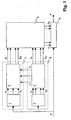
- FIG. 1 schematically shows a structure of the signal processing in a hearing aid according to the invention.
- An input signal X is fed to a controllable filter 6, to a means for determining a compression gain 7 and to a means for determining a noise suppression 8.
- the controllable filter 6 is designed to form an output signal Y in accordance with filter coefficients c 1 ... C M.
- the input signal X is fed to a first filter unit 1.
- the signal components x 1 .x N are used to calculate parameters or coefficients or adaptation values of the compression gain g 1 ..g M. These coefficients are also referred to as gain values with regard to the amplification function of the hearing aid. However, other coefficients are also referred to as gain values.
- the input signal X is fed to a second filter unit 2.
- the signal components y 1 .y M are used to calculate parameters or coefficients or adaptation values of the noise suppression a 1 .a M. These coefficients are also referred to as attenuation values in view of the noise suppression achieved thereby.
- the combining unit 5 combines the coefficients of the compression gain g 1 ..g M with the coefficients of noise suppression a 1 ..a M and calculates therefrom combined logarithmic amplification values c 1 ... c M as filter coefficients of the controllable filter 6.
- the noise suppression signal processing 4 transmits correction values r 1 ..r N corresponding to a respective signal attenuation caused by the noise suppression in the frequency ranges F 1 ..F n .
- the first filter unit 1 and the second filter unit 2 are not implemented as separate units, but as a combined filter unit. For example, filtering with broad frequency bands is carried out sequentially to determine the signal components x 1 ..x N , and these filtered signals are further filtered to determine the signal components y 1 ..y M.
- the invention in the embodiment shown works in summary as follows:
- the input signal is split into three signal paths, a main signal path with a controllable filter, a first parallel signal analysis path for the compression gain, and a second parallel signal analysis path for noise suppression.
- FIG. 12 shows a block diagram of a calculation of gain values in compression amplification signal processing 3.
- signal levels in N are computed in relatively few frequency ranges.
- FIG. 2 shows the calculation for one of these N frequency ranges, for the remaining frequency ranges the same structure is used.
- a signal component x n in this frequency range a signal power is formed in a block 21, for example, as a running sum of squared signal values.
- a signal level p n is formed by logarithmization.
- the term signal level here refers to the effective value of the instantaneous signal power in the frequency range F n expressed in a logarithmic number range, eg in dB.
- a modified signal level p n ' is calculated by subtracting 23 a correction value r n .
- correction values r n will be discussed separately below.
- Each frequency range F n of the compression gain is assigned at least one frequency range ⁇ m of the noise suppression.
- ⁇ m in the FIG. 2 if these are three, corresponding to blocks 24, 24 ', 24 "
- These functions f m into account an individual hearing loss and audiological experience.
- Parameters, amplification values or hearing correction values contained in the functions f m are preferably user-specific and stored, for example, in an EPROM of the hearing device.
- the total number of these functions f m and the gain values g m , ie over all N frequency ranges F n of the compression gain, is equal to the number M of the frequency ranges ⁇ m of the noise suppression.
- the signal levels p n must be determined such that Differences between quiet and loud consecutive phonemes are well captured.
- the continuously determined amplification values g m must be applied in a timely manner to those signal sections in which the associated phonemes are located, ie the amplification values must act synchronously on the audio signal X. So fast, in the rhythm of successive phonemes acting, synchronous compression gain gives only good results when the number of separate frequency ranges is chosen small, for example, N ⁇ 5, preferably N ⁇ 3.
- the signal analysis for determining signal levels in frequency ranges f n for the compression gain is preferably carried out iteratively, wherein current signal levels are determined for each new value of the input signal.
- recursive signal analysis methods are preferably used.
- the noise suppression is about attenuating sub-signals in frequency ranges of the audio signal, which are mainly only monotone noise.
- the signal level p m is formed in segments for segments of a length of about 20-30 ms as the instantaneous effective value of the signal power in the corresponding frequency range ⁇ m .
- the noise suppression can be tracked with a temporal resolution p m, for example under 50 ms.
- a stored maximum value is either reduced by a small increment linearly or according to an exponential function in each sampling interval, or the current level value is accepted if it exceeds this reduced maximum value.
- the minimum value is increased by a small increment in each sampling interval, or the current level value is adopted if it falls below the raised minimum value.
- the modulation depth is the difference between these two estimates. A small modulation depth thus arises at constant signal energy. In order to avoid sudden changes in the modulation depth, the difference values thus determined are preferably subjected to a smoothing process. By appropriate selection of the mentioned increments, the extremes with time constants in the range of a few seconds sound.
- the modulation depth assumes values of 30 dB and more.
- the low frequency range up to about 500 Hz is often dominated by monotone noise, so that even in the presence of speech signals, the modulation depth in this frequency range drops to near 0 dB.
- Other noise in turn covers the speech signal in higher frequency ranges.
- partial signals in frequency ranges ⁇ m are attenuated, in which the modulation depth d m below a critical value of eg 15 dB precipitated, the amount of attenuation a monotonic and m, for example, increases linearly with decreasing modulation depth.
- the gain values g m of the compression gain 3 and the attenuation values a m of the noise suppression 4 are combined per frequency range and fed as control quantities c m to the controllable filter 6 in the main signal path. If required, the transfer function of the controllable filter is tracked in each sampling interval of the input signal in a frequency-specific manner in one or a few frequency ranges and left unchanged in all other frequency ranges.
- the use of the segment-wise signal processing results in the following further disadvantages:
- the signal levels p n are calculated as mean values in a segment, whereby a pronounced signal rise at a specific time is detected only with the temporal resolution of a processing segment. Also, the determination of the individual gain values and thus the entire transfer function is carried out only in time with the successive segments.
- the filtering of the input signal X is performed on the basis of a separate and parallel signal analysis for the noise suppression as well as for the compression amplification.
- the combined and parallel processing takes place in detail as follows: In the lowest signal path, the audio signal passes through a controllable filter 6, which performs the required frequency-dependent signal modifications.
- the two upper signal paths each contain a filter unit which divides the audio signal into sub-signals of separate frequency ranges.
- the first filter unit 1 causes a signal division into only a few, N wide frequency ranges F n , which can be carried out with little signal delay.
- the second filter unit 2 causes a signal division into many, M narrow frequency ranges ⁇ m , which entails a long delay time.
- the frequency ranges are preferably selected such that each frequency range ⁇ m is a subrange of a frequency range F n .
- the frequency ranges to compression gain F n coincide preferably the same frequency range as the frequency ranges for noise suppression ⁇ m .
- a frequency range for compression amplification covers several frequency ranges for noise suppression. Ratios between the widths of frequency ranges and between the distribution of frequency ranges are preferably at least approximately logarithmic.
- a typical frequency range for the input signal is: 0 to 10 kHz.
- this is divided into the following frequency ranges for compression gain and noise cancellation: Compression gain (Hz) Noise suppression (Hz) 0 to 1250 0 to 312.5 312.5 to 625 625 to 937.5 937.5 to 1250 1250 to 2500 1250 to 1562.5 1562.5 to 1875 1875 to 2187.5 2187.5 to 2500 2500 to 10,000 2500 to 3125 3125 to 3750 3750 to 4375 4375 to 5000 50000 to 6250 6250 to 7500 7500 to 10000
- the sampling rate is for example 20 kHz and accordingly the useful bandwidth is half, that is 10 kHz. In another embodiment of the invention, these values are 16 kHz and 8 kHz, respectively.
- the signal analysis for noise suppression for each of the M frequency ranges ⁇ m is a determination of the associated signal level p m , the modulation depth d m and the attenuation value a m , the latter being advantageously expressed in a logarithmic number range.
- the determination of the modulation depth d m is carried out as described above in accordance with ie as a function of the time profile of the corresponding signal level p m , and the determination of the coefficients a m in accordance with the corresponding modulation depths d m .
- the second filter unit 2 and a part of the noise suppression signal processing 4 thus form a means for determining these quantities p m , d m and a m in a second set of frequency ranges of the input signal X.
- the signal level p n is determined such that each signal value of the sub-signal x n [ k] contributes to an update of the signal level, resulting in a higher temporal resolution than the mere Determination of a segment-wise mean value.
- the correction values r n take into account a possible attenuation of the signal power due to the noise suppression.
- the compression gain in the signal processing combined according to the invention is also realizable with a much more flexible transfer function, ie with M instead of only N functions f m , than if only one gain value for each broad frequency range F n would be set.
- the gain values g m are again preferably expressed in a logarithmic number range.
- the functions f m specify frequency-specific as a function of the signal level, a desired frequency-specific amplification according to audiological principles.
- the M combined logarithmic gain values c m arrive at the controllable filter 6, where they are transformed into linear gain values ⁇ m .
- delta H z ⁇ k ⁇ m k - ⁇ m ⁇ m ⁇ H m z .
- ⁇ m denotes the sampling interval in which the frequency range ⁇ m was last updated.
- the frequency range ⁇ m is updated in a specific sampling interval. For example, it is possible to update in each case that frequency range ⁇ m for which
- the following fact is taken into account by means of the correction values r 1 ..r n :
- the noise suppression determines attenuation values which depend only on the modulation depths but not on the signal levels themselves, as is correct for normal hearing persons. Hearing impaired people, whose subjective perception of loudness, however, in In general, in a non-linear manner with the signal level, a signal attenuation by a fixed value a m will be perceived differently depending on the signal level. In a serial processing, ie in a noise suppression with subsequent compression gain, this effect would be corrected automatically. However, since there is a parallel processing, the correction values r 1 ..r n are transmitted from the noise suppression to the compression gain to make this correction.
- Attenuation-related correction values r n are determined for the N signal levels of the compression gain, and the gain values are calculated with signal levels reduced by these correction values.
- the compression gain is corrected according to the noise suppression. This ensures that the signals optimally processed by means of noise suppression for the normal hearing person are individually correctly imaged in the hearing range of each hearing impaired person.
- the s [k] and the u [k] are added separately. From the logarithmic ratio of the two sums with respect to F is obtained n valid logarithmic correction value r n.
- FIG. 3 shows a block diagram for a corresponding signal processing, as in the signal processing for noise suppression 4 takes place to determine the correction quantities r n .
- a signal power s [k] is determined in a known manner on signal path 38 and from this a signal level in block 32, and from this in block 33 a modulation depth d m and therefrom in Block 34 has an attenuation value a m .
- the logarithmic attenuation value a m is linearly scaled, and the reduced signal power u [k] on signal path 36 is calculated by multiplication with the signal power s [k].
- the reduced signal power u [k] is calculated in parallel for each of the three frequency ranges, that is to say for y m , y m + 1 , y m + 2 , and summed up in node 37.
- Signal power s [k] of the three frequency ranges is summed in summation point 39.
- the sums are scaled logarithmically in blocks 40 and 41 respectively and in subtraction 41 the correction value r n is formed as a difference.
- the device according to the invention is preferably implemented at least partially as an analog circuit or microprocessor-based or using application-specific integrated circuits or with a combination of these techniques.
Landscapes
- Health & Medical Sciences (AREA)
- General Health & Medical Sciences (AREA)
- Neurosurgery (AREA)
- Otolaryngology (AREA)
- Physics & Mathematics (AREA)
- Engineering & Computer Science (AREA)
- Acoustics & Sound (AREA)
- Signal Processing (AREA)
- Tone Control, Compression And Expansion, Limiting Amplitude (AREA)
Priority Applications (4)
| Application Number | Priority Date | Filing Date | Title |
|---|---|---|---|
| EP03405125A EP1453355B1 (de) | 2003-02-26 | 2003-02-26 | Signalverarbeitung in einem Hörgerät |
| DK03405125.0T DK1453355T3 (da) | 2003-02-26 | 2003-02-26 | Signalbearbejdning i et høreapparat |
| AU2004200726A AU2004200726B2 (en) | 2003-02-26 | 2004-02-24 | Signal processing in a hearing aid |
| US10/784,152 US7340072B2 (en) | 2003-02-26 | 2004-02-24 | Signal processing in a hearing aid |
Applications Claiming Priority (1)
| Application Number | Priority Date | Filing Date | Title |
|---|---|---|---|
| EP03405125A EP1453355B1 (de) | 2003-02-26 | 2003-02-26 | Signalverarbeitung in einem Hörgerät |
Publications (2)
| Publication Number | Publication Date |
|---|---|
| EP1453355A1 EP1453355A1 (de) | 2004-09-01 |
| EP1453355B1 true EP1453355B1 (de) | 2012-10-24 |
Family
ID=32749030
Family Applications (1)
| Application Number | Title | Priority Date | Filing Date |
|---|---|---|---|
| EP03405125A Expired - Lifetime EP1453355B1 (de) | 2003-02-26 | 2003-02-26 | Signalverarbeitung in einem Hörgerät |
Country Status (4)
| Country | Link |
|---|---|
| US (1) | US7340072B2 (da) |
| EP (1) | EP1453355B1 (da) |
| AU (1) | AU2004200726B2 (da) |
| DK (1) | DK1453355T3 (da) |
Families Citing this family (9)
| Publication number | Priority date | Publication date | Assignee | Title |
|---|---|---|---|---|
| EP1453355B1 (de) * | 2003-02-26 | 2012-10-24 | Bernafon AG | Signalverarbeitung in einem Hörgerät |
| EP1703494A1 (en) * | 2005-03-17 | 2006-09-20 | Emma Mixed Signal C.V. | Listening device |
| KR100678770B1 (ko) * | 2005-08-24 | 2007-02-02 | 한양대학교 산학협력단 | 궤환 신호 제거 기능을 구비한 보청기 |
| US7774396B2 (en) * | 2005-11-18 | 2010-08-10 | Dynamic Hearing Pty Ltd | Method and device for low delay processing |
| GB0707640D0 (en) * | 2007-04-20 | 2007-05-30 | Strathclyde | Acoustic deterrence |
| DE102007030067B4 (de) * | 2007-06-29 | 2011-08-25 | Siemens Medical Instruments Pte. Ltd. | Hörgerät mit passiver, eingangspegelabhängiger Geräuschreduktion und Verfahren |
| WO2010051857A1 (en) * | 2008-11-10 | 2010-05-14 | Oticon A/S | N band fm demodulation to aid cochlear hearing impaired persons |
| US20120244969A1 (en) | 2011-03-25 | 2012-09-27 | May Patents Ltd. | System and Method for a Motion Sensing Device |
| EP2560410B1 (en) * | 2011-08-15 | 2019-06-19 | Oticon A/s | Control of output modulation in a hearing instrument |
Family Cites Families (4)
| Publication number | Priority date | Publication date | Assignee | Title |
|---|---|---|---|---|
| US6434246B1 (en) * | 1995-10-10 | 2002-08-13 | Gn Resound As | Apparatus and methods for combining audio compression and feedback cancellation in a hearing aid |
| AU771005B2 (en) * | 1999-07-08 | 2004-03-11 | Bernafon Ag | Hearing aid |
| EP1191813A1 (en) * | 2000-09-25 | 2002-03-27 | TOPHOLM & WESTERMANN APS | A hearing aid with an adaptive filter for suppression of acoustic feedback |
| EP1453355B1 (de) * | 2003-02-26 | 2012-10-24 | Bernafon AG | Signalverarbeitung in einem Hörgerät |
-
2003
- 2003-02-26 EP EP03405125A patent/EP1453355B1/de not_active Expired - Lifetime
- 2003-02-26 DK DK03405125.0T patent/DK1453355T3/da active
-
2004
- 2004-02-24 AU AU2004200726A patent/AU2004200726B2/en not_active Ceased
- 2004-02-24 US US10/784,152 patent/US7340072B2/en not_active Expired - Lifetime
Also Published As
| Publication number | Publication date |
|---|---|
| US20040175011A1 (en) | 2004-09-09 |
| US7340072B2 (en) | 2008-03-04 |
| AU2004200726A1 (en) | 2004-09-16 |
| DK1453355T3 (da) | 2013-02-11 |
| EP1453355A1 (de) | 2004-09-01 |
| AU2004200726B2 (en) | 2008-12-11 |
Similar Documents
| Publication | Publication Date | Title |
|---|---|---|
| DE69428119T2 (de) | Verringerung des hintergrundrauschens zur sprachverbesserung | |
| DE69915711T2 (de) | Verfahren und signalprozessor zur verstärkung von sprachsignal-komponenten in einem hörhilfegerät | |
| DE69313480T2 (de) | Rauschverminderungseinrichtung | |
| DE69933141T2 (de) | Tonprozessor zur adaptiven dynamikbereichsverbesserung | |
| DE69630580T2 (de) | Rauschunterdrücker und Verfahren zur Unterdrückung des Hintergrundrauschens in einem verrauschten Sprachsignal und eine Mobilstation | |
| EP1919257B1 (de) | Pegelabhängige Geräuschreduktion | |
| EP2158588B1 (de) | Spektralglättungsverfahren von verrauschten signalen | |
| EP1647972B1 (de) | Verbesserung der Verständlichkeit von Sprache enthaltenden Audiosignalen | |
| EP1453194A2 (de) | Verfahren zur automatischen Verstärkungseinstellung in einem Hörhilfegerät sowie Hörhilfegerät | |
| EP1143416A2 (de) | Geräuschunterdrückung im Zeitbereich | |
| EP1103956B1 (de) | Exponentielle Echo- und Geräuschabsenkung in Sprachpausen | |
| EP3393143B1 (de) | Verfahren zum betrieb eines hörgerätes | |
| EP1453355B1 (de) | Signalverarbeitung in einem Hörgerät | |
| EP3089481B1 (de) | Verfahren zur frequenzabhängigen rauschunterdrückung eines eingangssignals | |
| EP2080197B1 (de) | Vorrichtung zur geräuschunterdrückung bei einem audiosignal | |
| DE112016004394T5 (de) | Heulunterdrückungsvorrichtung | |
| DE602004006912T2 (de) | Verfahren zur Verarbeitung eines akustischen Signals und ein Hörgerät | |
| EP1052881B1 (de) | Hörhilfsgerät mit Oszillationsdetektor sowie Verfahren zur Feststellung von Oszillationen in einem Hörhilfsgerät | |
| DE19624092B4 (de) | Verstärkungsschaltung, vorzugsweise für analoge oder digitale Hörgeräte sowie Hörgeräte unter Verwendung einer entsprechenden Verstärkungsschaltung bzw. eines entsprechenden Signalverarbeitungs-Algorithmus | |
| EP0779706B1 (de) | Schaltungsanordnung zur Verbesserung des Störabstandes | |
| EP1458216B1 (de) | Vorrichtung und Verfahren zur Adaption von Hörgerätemikrofonen | |
| EP1351550B1 (de) | Verfahren zur Anpassung einer Signalverstärkung in einem Hörgerät sowie ein Hörgerät | |
| EP0777326A2 (de) | Verfahren und Vorrichtung zur Filterung eines Audiosignals | |
| DE102012204193B4 (de) | Audioprozessor und Verfahren zum Verstärken oder Dämpfen eines empfangenen Audiosignals | |
| EP1869765B1 (de) | Kompandersystem |
Legal Events
| Date | Code | Title | Description |
|---|---|---|---|
| PUAI | Public reference made under article 153(3) epc to a published international application that has entered the european phase |
Free format text: ORIGINAL CODE: 0009012 |
|
| AK | Designated contracting states |
Kind code of ref document: A1 Designated state(s): AT BE BG CH CY CZ DE DK EE ES FI FR GB GR HU IE IT LI LU MC NL PT SE SI SK TR |
|
| AX | Request for extension of the european patent |
Extension state: AL LT LV MK RO |
|
| 17P | Request for examination filed |
Effective date: 20040903 |
|
| AKX | Designation fees paid |
Designated state(s): AT BE BG CH CY CZ DE DK EE ES FI FR GB GR HU IE IT LI LU MC NL PT SE SI SK TR |
|
| GRAP | Despatch of communication of intention to grant a patent |
Free format text: ORIGINAL CODE: EPIDOSNIGR1 |
|
| GRAS | Grant fee paid |
Free format text: ORIGINAL CODE: EPIDOSNIGR3 |
|
| GRAA | (expected) grant |
Free format text: ORIGINAL CODE: 0009210 |
|
| AK | Designated contracting states |
Kind code of ref document: B1 Designated state(s): AT BE BG CH CY CZ DE DK EE ES FI FR GB GR HU IE IT LI LU MC NL PT SE SI SK TR |
|
| REG | Reference to a national code |
Ref country code: GB Ref legal event code: FG4D Free format text: NOT ENGLISH |
|
| REG | Reference to a national code |
Ref country code: CH Ref legal event code: EP |
|
| REG | Reference to a national code |
Ref country code: CH Ref legal event code: NV Representative=s name: FIAMMENGHI-FIAMMENGHI, CH Ref country code: AT Ref legal event code: REF Ref document number: 581452 Country of ref document: AT Kind code of ref document: T Effective date: 20121115 |
|
| REG | Reference to a national code |
Ref country code: IE Ref legal event code: FG4D Free format text: LANGUAGE OF EP DOCUMENT: GERMAN |
|
| REG | Reference to a national code |
Ref country code: DE Ref legal event code: R096 Ref document number: 50314550 Country of ref document: DE Effective date: 20121220 |
|
| REG | Reference to a national code |
Ref country code: DK Ref legal event code: T3 |
|
| REG | Reference to a national code |
Ref country code: NL Ref legal event code: VDEP Effective date: 20121024 |
|
| PG25 | Lapsed in a contracting state [announced via postgrant information from national office to epo] |
Ref country code: NL Free format text: LAPSE BECAUSE OF FAILURE TO SUBMIT A TRANSLATION OF THE DESCRIPTION OR TO PAY THE FEE WITHIN THE PRESCRIBED TIME-LIMIT Effective date: 20121024 Ref country code: SE Free format text: LAPSE BECAUSE OF FAILURE TO SUBMIT A TRANSLATION OF THE DESCRIPTION OR TO PAY THE FEE WITHIN THE PRESCRIBED TIME-LIMIT Effective date: 20121024 Ref country code: FI Free format text: LAPSE BECAUSE OF FAILURE TO SUBMIT A TRANSLATION OF THE DESCRIPTION OR TO PAY THE FEE WITHIN THE PRESCRIBED TIME-LIMIT Effective date: 20121024 |
|
| PG25 | Lapsed in a contracting state [announced via postgrant information from national office to epo] |
Ref country code: SI Free format text: LAPSE BECAUSE OF FAILURE TO SUBMIT A TRANSLATION OF THE DESCRIPTION OR TO PAY THE FEE WITHIN THE PRESCRIBED TIME-LIMIT Effective date: 20121024 Ref country code: PT Free format text: LAPSE BECAUSE OF FAILURE TO SUBMIT A TRANSLATION OF THE DESCRIPTION OR TO PAY THE FEE WITHIN THE PRESCRIBED TIME-LIMIT Effective date: 20130225 Ref country code: GR Free format text: LAPSE BECAUSE OF FAILURE TO SUBMIT A TRANSLATION OF THE DESCRIPTION OR TO PAY THE FEE WITHIN THE PRESCRIBED TIME-LIMIT Effective date: 20130125 Ref country code: CY Free format text: LAPSE BECAUSE OF FAILURE TO SUBMIT A TRANSLATION OF THE DESCRIPTION OR TO PAY THE FEE WITHIN THE PRESCRIBED TIME-LIMIT Effective date: 20121024 |
|
| PG25 | Lapsed in a contracting state [announced via postgrant information from national office to epo] |
Ref country code: EE Free format text: LAPSE BECAUSE OF FAILURE TO SUBMIT A TRANSLATION OF THE DESCRIPTION OR TO PAY THE FEE WITHIN THE PRESCRIBED TIME-LIMIT Effective date: 20121024 Ref country code: BG Free format text: LAPSE BECAUSE OF FAILURE TO SUBMIT A TRANSLATION OF THE DESCRIPTION OR TO PAY THE FEE WITHIN THE PRESCRIBED TIME-LIMIT Effective date: 20130124 Ref country code: SK Free format text: LAPSE BECAUSE OF FAILURE TO SUBMIT A TRANSLATION OF THE DESCRIPTION OR TO PAY THE FEE WITHIN THE PRESCRIBED TIME-LIMIT Effective date: 20121024 Ref country code: CZ Free format text: LAPSE BECAUSE OF FAILURE TO SUBMIT A TRANSLATION OF THE DESCRIPTION OR TO PAY THE FEE WITHIN THE PRESCRIBED TIME-LIMIT Effective date: 20121024 |
|
| PG25 | Lapsed in a contracting state [announced via postgrant information from national office to epo] |
Ref country code: IT Free format text: LAPSE BECAUSE OF FAILURE TO SUBMIT A TRANSLATION OF THE DESCRIPTION OR TO PAY THE FEE WITHIN THE PRESCRIBED TIME-LIMIT Effective date: 20121024 |
|
| PLBE | No opposition filed within time limit |
Free format text: ORIGINAL CODE: 0009261 |
|
| STAA | Information on the status of an ep patent application or granted ep patent |
Free format text: STATUS: NO OPPOSITION FILED WITHIN TIME LIMIT |
|
| BERE | Be: lapsed |
Owner name: BERNAFON A.G. Effective date: 20130228 |
|
| PG25 | Lapsed in a contracting state [announced via postgrant information from national office to epo] |
Ref country code: MC Free format text: LAPSE BECAUSE OF NON-PAYMENT OF DUE FEES Effective date: 20130228 |
|
| 26N | No opposition filed |
Effective date: 20130725 |
|
| PG25 | Lapsed in a contracting state [announced via postgrant information from national office to epo] |
Ref country code: ES Free format text: LAPSE BECAUSE OF FAILURE TO SUBMIT A TRANSLATION OF THE DESCRIPTION OR TO PAY THE FEE WITHIN THE PRESCRIBED TIME-LIMIT Effective date: 20130204 |
|
| REG | Reference to a national code |
Ref country code: DE Ref legal event code: R097 Ref document number: 50314550 Country of ref document: DE Effective date: 20130725 |
|
| REG | Reference to a national code |
Ref country code: IE Ref legal event code: MM4A |
|
| PG25 | Lapsed in a contracting state [announced via postgrant information from national office to epo] |
Ref country code: IE Free format text: LAPSE BECAUSE OF NON-PAYMENT OF DUE FEES Effective date: 20130226 Ref country code: BE Free format text: LAPSE BECAUSE OF NON-PAYMENT OF DUE FEES Effective date: 20130228 |
|
| REG | Reference to a national code |
Ref country code: AT Ref legal event code: MM01 Ref document number: 581452 Country of ref document: AT Kind code of ref document: T Effective date: 20130226 |
|
| PG25 | Lapsed in a contracting state [announced via postgrant information from national office to epo] |
Ref country code: AT Free format text: LAPSE BECAUSE OF NON-PAYMENT OF DUE FEES Effective date: 20130226 |
|
| PG25 | Lapsed in a contracting state [announced via postgrant information from national office to epo] |
Ref country code: TR Free format text: LAPSE BECAUSE OF FAILURE TO SUBMIT A TRANSLATION OF THE DESCRIPTION OR TO PAY THE FEE WITHIN THE PRESCRIBED TIME-LIMIT Effective date: 20121024 |
|
| PG25 | Lapsed in a contracting state [announced via postgrant information from national office to epo] |
Ref country code: LU Free format text: LAPSE BECAUSE OF NON-PAYMENT OF DUE FEES Effective date: 20130226 Ref country code: HU Free format text: LAPSE BECAUSE OF FAILURE TO SUBMIT A TRANSLATION OF THE DESCRIPTION OR TO PAY THE FEE WITHIN THE PRESCRIBED TIME-LIMIT; INVALID AB INITIO Effective date: 20030226 |
|
| REG | Reference to a national code |
Ref country code: FR Ref legal event code: PLFP Year of fee payment: 14 |
|
| REG | Reference to a national code |
Ref country code: FR Ref legal event code: PLFP Year of fee payment: 15 |
|
| REG | Reference to a national code |
Ref country code: FR Ref legal event code: PLFP Year of fee payment: 16 |
|
| REG | Reference to a national code |
Ref country code: CH Ref legal event code: PUE Owner name: OTICON A/S, DK Free format text: FORMER OWNER: BERNAFON AG, CH |
|
| REG | Reference to a national code |
Ref country code: DE Ref legal event code: R082 Ref document number: 50314550 Country of ref document: DE Ref country code: DE Ref legal event code: R081 Ref document number: 50314550 Country of ref document: DE Owner name: OTICON A/S, DK Free format text: FORMER OWNER: BERNAFON AG, BERN, CH |
|
| REG | Reference to a national code |
Ref country code: GB Ref legal event code: 732E Free format text: REGISTERED BETWEEN 20191003 AND 20191009 |
|
| PGFP | Annual fee paid to national office [announced via postgrant information from national office to epo] |
Ref country code: GB Payment date: 20220128 Year of fee payment: 20 Ref country code: DK Payment date: 20220128 Year of fee payment: 20 Ref country code: DE Payment date: 20220201 Year of fee payment: 20 Ref country code: CH Payment date: 20220203 Year of fee payment: 20 |
|
| PGFP | Annual fee paid to national office [announced via postgrant information from national office to epo] |
Ref country code: FR Payment date: 20220128 Year of fee payment: 20 |
|
| REG | Reference to a national code |
Ref country code: DE Ref legal event code: R071 Ref document number: 50314550 Country of ref document: DE |
|
| REG | Reference to a national code |
Ref country code: DK Ref legal event code: EUP Expiry date: 20230226 |
|
| REG | Reference to a national code |
Ref country code: CH Ref legal event code: PL |
|
| REG | Reference to a national code |
Ref country code: GB Ref legal event code: PE20 Expiry date: 20230225 |
|
| PG25 | Lapsed in a contracting state [announced via postgrant information from national office to epo] |
Ref country code: GB Free format text: LAPSE BECAUSE OF EXPIRATION OF PROTECTION Effective date: 20230225 |