EP1453640B1 - Akku-handwerkzeugmaschine - Google Patents
Akku-handwerkzeugmaschine Download PDFInfo
- Publication number
- EP1453640B1 EP1453640B1 EP02774298A EP02774298A EP1453640B1 EP 1453640 B1 EP1453640 B1 EP 1453640B1 EP 02774298 A EP02774298 A EP 02774298A EP 02774298 A EP02774298 A EP 02774298A EP 1453640 B1 EP1453640 B1 EP 1453640B1
- Authority
- EP
- European Patent Office
- Prior art keywords
- housing
- battery pack
- auxiliary tool
- hand
- held power
- Prior art date
- Legal status (The legal status is an assumption and is not a legal conclusion. Google has not performed a legal analysis and makes no representation as to the accuracy of the status listed.)
- Expired - Lifetime
Links
- 238000003780 insertion Methods 0.000 claims description 8
- 230000037431 insertion Effects 0.000 claims description 8
- 238000007373 indentation Methods 0.000 claims description 2
- 208000027418 Wounds and injury Diseases 0.000 description 2
- 230000006378 damage Effects 0.000 description 2
- 208000014674 injury Diseases 0.000 description 2
- 230000035515 penetration Effects 0.000 description 1
- 230000001681 protective effect Effects 0.000 description 1
Images


Classifications
-
- B—PERFORMING OPERATIONS; TRANSPORTING
- B25—HAND TOOLS; PORTABLE POWER-DRIVEN TOOLS; MANIPULATORS
- B25F—COMBINATION OR MULTI-PURPOSE TOOLS NOT OTHERWISE PROVIDED FOR; DETAILS OR COMPONENTS OF PORTABLE POWER-DRIVEN TOOLS NOT PARTICULARLY RELATED TO THE OPERATIONS PERFORMED AND NOT OTHERWISE PROVIDED FOR
- B25F5/00—Details or components of portable power-driven tools not particularly related to the operations performed and not otherwise provided for
- B25F5/02—Construction of casings, bodies or handles
- B25F5/029—Construction of casings, bodies or handles with storage compartments
Definitions
- the present invention relates to a cordless power tool according to the preamble of claim 1.
- cordless hand tool machines are known in which between the housing and the detachable battery pack, an elongate auxiliary tool is placed invisibly from the outside, which is removable only after removal of the battery pack.
- the auxiliary tool serves to release or attach the tool of the cordless power tool, e.g. the saw blade of a hand saw.
- the invention with the features of claim 1 has the advantage that the auxiliary tool is secured to exposed position of the cordless power tool against loss but housed clearly visible and particularly fast, so to speak blind, is available.
- the auxiliary tool is designed to be angled, wherein both ends are mounted in the housing and a central region, in particular the angled portion protrudes from the housing, the auxiliary tool forms a projection which is particularly good palpable or tangible.
- the auxiliary tool forms by this arrangement an eyelet on which it can be hung, stored or transported.
- the auxiliary tool can be comfortably grasped and particularly easily removed, at least by a finger.
- the auxiliary tool has two, in particular a longer and shorter leg, wherein the one leg in a hidden by the battery pack hole in the housing parallel to the battery insertion direction can be inserted and the other leg in a groove in the housing adjacent to the battery Pack is inserted, the auxiliary tool is stored vibration protected and the risk of rattling noises when working with the cordless power tool excluded.
- the auxiliary tool can only be removed when the battery pack has been released and is captively locked to the handheld power tool by the inserted battery pack, the auxiliary tool can not be removed while the battery pack can be activated, thus ensuring the safety of the user during the tool change and the Risk of injury is minimized.
- Figure 1 shows a side view of a designed as a circular saw hand tool 10, the housing 12 with a handle 14 for the holding hand and a guide handle 15 for the leading hand of the user.
- the main handle 14 carries a switch button 16 for switching on and off of the drive motor, not shown.
- a laterally depressible locking button 17 is arranged for detecting the shift key 16 in the switch-on mode.
- a saw blade housing 19 Flanged laterally to the housing 12 is a saw blade housing 19, which carries a motor housing 18, which extends in the viewing direction out of the plane of the drawing.
- the housing 12 and the saw blade housing 19 are coupled to a base plate and mounted by means of a joint 24 adjustable in height and pivotally.
- the joint 24 can be locked, so that any pivotal positions of the housing 12, 18 relative to the base plate 22 can be determined.
- a battery pack 28 from the housing 12 occurs in the viewing direction right down parallel to the extension of the main handle 14, a battery pack 28 from.
- This has lateral release buttons 30, by the impressions of the battery pack 28 from the housing 12 parallel to the main handle 14 releasably or according to the movement arrow 46 is removable.
- In extension of the lower edge 32 of the housing 12 extends designed as a hexagon wrench auxiliary tool 38 which protrudes outward at an angle out of the contour of the housing 12 and defines a passage opening 50.
- the auxiliary tool 38 enters with a long leg 35 parallel to the insertion of the battery pack 28 in a tight, resilient insertion opening 40 into the interior of the housing 12 and is with its short leg 37 in an insertion groove 42 parallel to the lower edge of the housing 12 flush to the Groove base 44 can be inserted.
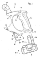
- Figure 2 shows the housing 12 of the power tool 10 without motor housing 18 and without saw blade housing 19 in exploded view with the battery pack 28 and the auxiliary tool 38th
- a contact cylinder 29 of the battery pack 28 is clearly visible, with which, the battery pack 28 - according to the movement arrow 46 - deep into the interior of the handle 14 and the housing 12 is inserted.
- the auxiliary tool 38 also referred to as Allen key, is pushed with its long leg into the insertion opening 40 and to the stop of the shorter leg 37 on Groove base 44 can be inserted. Only then can the battery pack 28 be latchably secured to the housing 12.
- the removal of the battery pack 28 is done in the opposite direction as the insertion. Only after removing the battery pack 28 from the housing 12 is also a removal of the auxiliary tool 38 at all or comfortably possible.
- the passage opening 50 which is formed by the indentation 43 formed by a concave housing contour of the housing 12 and the angled portion of the auxiliary tool 38.
- the housing 12 has lateral screw openings 74, 76, through which screws 34, 36 can be plugged, with which the saw blade housing 19 can be screwed laterally to the housing 12 in the manner of a flange.
- the auxiliary tool 38 can therefore only be taken out of the housing 12 when the battery pack 28 is removed.
- a hexagon socket screw (not shown) for fastening the saw blade not shown on the motor shaft can then be screwed in the loosening direction or fastening direction. This ensures that accidentally touching the switch button 16, the electric motor of the cordless power tool is not set in motion and the user is then injured in the saw blade change by the rotation.
Landscapes
- Engineering & Computer Science (AREA)
- Mechanical Engineering (AREA)
- Sawing (AREA)
- Battery Mounting, Suspending (AREA)
Description
- Die vorliegende Erfindung geht aus von einer Akku-Handwerkzeugmaschine nach dem Oberbegriff des Anspruchs 1.
- Es sind schon Akku-Handwerkzeugmaschinen bekannt, bei denen zwischen dem Gehäuse und dem lösbaren Akku-Pack ein längliches Hilfswerkzeug von außen unsichtbar untergebracht ist, das nur nach Entnahme des Akku-Packs herausnehmbar ist.
- Das Hilfswerkzeug dient dabei zum Lösen bzw. Befestigen des Werkzeugs der Akku-Handwerkzeugmaschine, z.B. des Sägeblatts einer Handsäge. Durch die besagte Unterbringung des Hilfswerkzeugs zwischen dem Akku-Pack und dem Gehäuse ist gesichert, dass ein Sägeblattwechsel nur bei gelöstem Akku-Pack möglich ist. Dadurch ist auszuschließen, dass bei versehentlichem Berühren der Schalttaste das Sägeblatt während des Sägeblattwechsels bewegt wird und den Benutzer verletzt.
- Da das Hilfswerkzeug zwischen Akku-Pack und Gehäuse unsichtbar versteckt ist, ist es schwerer aufzufinden. Schlimmstenfalls vergißt der Benutzer, wo das Hilfswerkzeug untergebracht ist und benützt ohne Abnehmen des Akkus ein anderes passendes Hilfswerkzeug mit der bereits geschilderten Verletzungsgefahr.
- Die Erfindung mit den Merkmalen des Anspruchs 1 hat den Vorteil, dass das Hilfswerkzeug an exponierter Lage der Akku-Handwerkzeugmaschine gegen Verlieren gesichert aber deutlich sichtbar untergebracht ist und besonders schnell, sozusagen blind, verfügbar ist.
- Dadurch, dass das Hilfswerkzeug winklig ausgestaltet ist, wobei beide Enden im Gehäuse gelagert sind und ein mittlerer Bereich, insbesondere der winklige Bereich, aus dem Gehäuse herausragt, bildet das Hilfswerkzeug einen Vorsprung, der besonders gut tastbar bzw. greifbar ist.
- Dadurch; dass der winklige Bereich des Hilfswerkzeugs soweit über die Außenkontur des Gehäuses heraustritt, daß er durchgreifbar ist, kann er bei hakenartigem Durchgriff des Fingers nach Abnahme des Akku-Packs besonders einfach entnommen werden. Außerdem bildet das Hilfswerkzeug durch diese Anordnung eine Öse, an der es aufhängbar, lagerbar bzw. transportierbar ist.
- Dadurch, dass die Außenkontur des Gehäuses im Bereich der heraustretenden Hilfswerkzeugs einen Einzug bildet, ist das Hilfswerkzeug zumindest von einem Finger bequem durchgreifbar und besonders einfach entnehmbar.
- Dadurch, dass das Hilfswerkzeug zwei, insbesondere einen längeren und kürzeren Schenkel aufweist, wobei der eine Schenkel in ein durch den Akku-Pack verdecktes Loch im Gehäuse parallel zur Akku-Einschubrichtung einsteckbar ist und der andere Schenkel in eine Nut im Gehäuse benachbart zum Akku-Pack einlegbar ist, ist das Hilfswerkzeug vibrationsgeschützt aufbewahrt und die Gefahr von Klappergeräuschen beim Arbeiten mit der Akku-Handwerkzeugmaschine ausgeschlossen.
- Dadurch, dass das Hilfswerkzeug nur bei gelöstem Akku-Pack entnehmbar ist und durch den eingesteckten Akku-Pack unverlierbar an der Handwerkzeugmaschine verriegelt ist, kann das Hilfswerkzeug nicht bei aktivierbarem Akku-Pack entnommen werden, so dass die Sicherheit des Benutzers beim Werkzeugwechsel gewährleistet und die Verletzungsgefahr minimiert ist.
- Nachstehend ist die vorliegende Erfindung anhand eines Ausführungsbeispiels mit zugehöriger Zeichnung erläutert.
- Es zeigen
- Figur 1 eine Seitenansicht der Handwerkzeugmaschine mit Hilfswerkzeug,
- Figur 2 einen Handgriffteil der Handwerkzeugmaschine mit Akku-Pack und Hilfswerkzeug als Explosionsdarstellung und
- Figur 3 die Darstellung gemäß Figur 2 zusammengekuppelt.
- Figur 1 zeigt eine Seitenansicht einer als Kreissäge ausgestalteten Handwerkzeugmaschine 10, deren Gehäuse 12 mit einem Handgriff 14 für die haltende Hand und einen Führungshandgriff 15 für die führende Hand des Benutzers.
- Der Haupthandgriff 14 trägt eine Schalttaste 16 zum Ein- und Ausschalten des nicht dargestellten Antriebsmotors. Oberhalb der Schalttaste 16 ist ein seitlich eindrückbarer Arretierknopf 17 zum Feststellen der Schalttaste 16 im Einschaltmodus angeordnet.
- Seitlich an das Gehäuse 12 angeflanscht ist ein Sägeblattgehäuse 19, das ein Motorgehäuse 18 trägt, das sich in Betrachtungsrichtung aus der Zeichenebene heraus erstreckt.
- Unten trägt das Sägeblattgehäuse 19 eine Pendeischutzhaube 20, die schützend das nicht dargestellte Kreissägeblatt umgreift.
- Das Gehäuse 12 und das Sägeblattgehäuse 19 sind mit einer Fußplatte gekoppelt und mittels eines Gelenks 24 daran höhenverstellbar und schwenkbar gelagert.
- Mittels einer Feststellschraube 26 ist das Gelenk 24 arretierbar, so dass beliebige Schwenkpositionen des Gehäuses 12, 18 gegenüber der Fußplatte 22 feststellbar sind.
- Aus dem Gehäuse 12 tritt in Betrachtungsrichtung rechts nach unten parallel zur Erstreckung des Haupthandgriffs 14 ein Akku-Pack 28 aus. Dieses hat seitliche Lösetasten 30, durch deren Eindrücken der Akku-Pack 28 vom Gehäuse 12 parallel zum Haupthandgriff 14 lösbar bzw. entsprechend dem Bewegungspfeil 46 abnehmbar ist. In Verlängerung des Unterrandes 32 des Gehäuses 12 erstreckt sich ein als Sechskantwinkelschlüssel ausgestaltetes Hilfswerkzeug 38, das winklig nach außen aus der Kontur des Gehäuses 12 herausragt und eine Durchgriffsöffnung 50 definiert.
- Das Hilfswerkzeug 38 tritt mit einem langen Schenkel 35 parallel zur Einsteckrichtung des Akku-Packs 28 in eine enggepasste, federnde Einstecköffnung 40 ins Innere des Gehäuses 12 und ist dabei mit ihrem kurzen Schenkel 37 in einer Einlegenut 42 parallel zum Unterrand des Gehäuses 12 bündig bis zum Nutgrund 44 einlegbar.
- Figur 2 zeigt das Gehäuse 12 der Handwerkzeugmaschine 10 ohne Motorgehäuse 18 und ohne Sägeblattgehäuse 19 in auseinandergezogener Darstellung mit dem Akku-Pack 28 und dem Hilfswerkzeug 38.
- Dabei ist ein Kontaktzylinder 29 des Akku-Packs 28 deutlich erkennbar, mit dem, der Akku-Pack 28 - entsprechend dem Bewegungspfeil 46 - tief ins Innere des Handgriffs 14 bzw. des Gehäuses 12 eingeschoben wird.
- Das Hilfswerkzeug 38, auch als Imbusschlüssel bezeichnet, ist mit seinem langen Schenkel in die Einstecköffnung 40 geschoben und bis zum Anschlag des kürzeren Schenkels 37 am Nutgrund 44 einschiebbar. Erst dann kann der Akku-Pack 28 einrastbar am Gehäuse 12 befestigt werden.
- Das Abnehmen des Akku-Packs 28 geschieht in umgekehrter Richtung wie das Einfügen. Erst nach Abnehmen des Akku-Packs 28 vom Gehäuse 12 ist auch ein Entnehmen des Hilfswerkzeugs 38 überhaupt bzw. bequem möglich. Durch Eingreifen in die Durchgriffsöffnung 50, die von dem durch eine konkav gewölbte Gehäusekontur gebildeten Einzug 43 des Gehäuses 12 und dem winkligen Bereich des Hilfswerkzeugs 38 gebildet wird.
- Das Gehäuse 12 weist seitliche Schrauböffnungen 74, 76 auf, durch das Schrauben 34, 36 steckbar sind, mit denen das Sägeblattgehäuse 19 flanschartig seitlich an das Gehäuse 12 schraubbar ist.
- Das Hilfswerkzeug 38 kann demnach nur bei entnommenem Akku-Pack 28 aus dem Gehäuse 12 genommen werden. Mit dem Hilfswerkzeug 38 kann dann eine nicht dargestellte Innensechskantschraube zur Befestigung des nicht mit dargestellten Sägeblatts auf der Motorwelle schraubend in Löserichtung bzw. Befestigungsrichtung gedreht werden. Damit ist gewährleistet, dass bei versehentlichem Berühren der Schalttaste 16 der Elektromotor der Akkuhandwerkzeugmaschine nicht in Bewegung gesetzt wird und der Benutzer dann beim Sägeblattwechsel durch dessen Rotation verletzt wird.
Claims (7)
- Akku-Handwerkzeugmaschine (10), insbesondere Handsägemaschine (101), mit einem Gehäuse (12), an dem ein Akku-Pack (28) unverlierbar, lösbar einsteckbar ist, wobei zwischen dem Akku-Pack (28) und dem Gehäuse (12) ein längliches Hilfswerkzeug (38) aufbewahrt ist, inbesondere zum Lösen des Werkzeugs, vorzugsweise des Sägeblatts, dadurch gekennzeichnet, daß das Hilfswerkzeug (38) von außen sichtbar und bequem tastbar, insbesondere durchgreifbar, angeordnet ist.
- Handwerkzeugmaschine nach Anspruch 1, dadurch gekennzeichnet, daß das Hilfswerkzeug (38) winklig, insbesondere 1-förmig, ausgestaltet ist, wobei beide Enden (35, 37) von außen unsichtbar im Gehäuse (12) gelagert sind und ein mittlerer Bereich, insbesondere der winklige Bereich, aus dem Gehäuse (12) heraustritt.
- Handwerkzeugmaschine nach Anspruch 1 oder 2, dadurch gekennzeichnet, daß der winklige Bereich des Hilfswerkzeugs (38) über die Außenkontur der Gehäuses (12) hinaus heraustritt.
- Handwerkzeugmaschine nach einem der Ansprüche 1 bis 3, dadurch gekennzeichnet, daß die Außenkontur des Gehäuses (12) einen Einzug (43) bildet, der zumindest miton einem Finger durchgreifbar ist.
- Handwerkzeugmaschine nach einem der Ansprüche 1 bis 4, dadurch gekennzeichnet, daß das Hilfswerkzeug (38) zwei, insbesondere einen längeren und einen kürzeren, Schenkel (35, 37) aufweist, wobei der eine Schenkel in ein durch den Akku-Pack (28) verdecktes Loch im Gehäuse (12) parallel zur Akku-Einschubrichtung einsteckbar ist und der andere Schenkel in eine.Nut (42) im Gehäuse (12) benachbart zum Akku-Pack (28) einlegbar ist.
- Handwerkzeugmaschine nach einem der Ansprüche 1 bis 5, dadurch gekennzeichnet, daß das Hilfswerkzeug (38) nur bei vollständig vom Gehäuse (12) gelöstem Akkupack (28) entnehmbar ist.
- Handwerkzeugmaschine nach einem der Ansprüche 1 bis 6, dadurch gekennzeichnet, daß das Hilfswerkzeug (38) durch Einstecken des Akkupacks (28) unlösbar verriegelt am Gehäuse (12) festgelegt ist.
Applications Claiming Priority (3)
| Application Number | Priority Date | Filing Date | Title |
|---|---|---|---|
| DE10159050A DE10159050A1 (de) | 2001-11-30 | 2001-11-30 | Akku-Handwerkzeugmaschine |
| DE10159050 | 2001-11-30 | ||
| PCT/DE2002/003263 WO2003047818A1 (de) | 2001-11-30 | 2002-09-04 | Akku-handwerkzeugmaschine |
Publications (2)
| Publication Number | Publication Date |
|---|---|
| EP1453640A1 EP1453640A1 (de) | 2004-09-08 |
| EP1453640B1 true EP1453640B1 (de) | 2006-06-07 |
Family
ID=7707698
Family Applications (1)
| Application Number | Title | Priority Date | Filing Date |
|---|---|---|---|
| EP02774298A Expired - Lifetime EP1453640B1 (de) | 2001-11-30 | 2002-09-04 | Akku-handwerkzeugmaschine |
Country Status (6)
| Country | Link |
|---|---|
| US (1) | US6889439B2 (de) |
| EP (1) | EP1453640B1 (de) |
| JP (1) | JP2005511329A (de) |
| CN (1) | CN1308121C (de) |
| DE (2) | DE10159050A1 (de) |
| WO (1) | WO2003047818A1 (de) |
Families Citing this family (48)
| Publication number | Priority date | Publication date | Assignee | Title |
|---|---|---|---|---|
| USD502073S1 (en) * | 2003-03-10 | 2005-02-22 | Positec Power Tools (Suzhou) Co., Ltd. | Circular saw |
| USD521835S1 (en) * | 2004-01-27 | 2006-05-30 | Makita Corporation | Circular saw |
| USD521336S1 (en) * | 2004-07-09 | 2006-05-23 | Choon Nang Electrical Appliance Mfy., Ltd. | Circular saw |
| USD527599S1 (en) * | 2004-08-27 | 2006-09-05 | Winsource Industries Limited | Electric circular saw |
| USD520830S1 (en) * | 2004-11-29 | 2006-05-16 | Hitachi Koki Co., Ltd. | Portable electric circular saw |
| CN2762964Y (zh) * | 2005-01-10 | 2006-03-08 | 南京德朔实业有限公司 | 用电池供电的电动工具 |
| USD520831S1 (en) * | 2005-03-09 | 2006-05-16 | Hitachi Koki Co., Ltd. | Portable electric circular saw |
| USD522833S1 (en) * | 2005-04-22 | 2006-06-13 | Makita Corporation | Portable electric circular saw |
| USD531473S1 (en) * | 2005-10-12 | 2006-11-07 | Black & Decker Inc. | Power tool |
| US20070089301A1 (en) * | 2005-10-21 | 2007-04-26 | Arias David A | Carving apparatus |
| DE102006018006B4 (de) * | 2006-04-07 | 2014-01-09 | Robert Bosch Gmbh | Akkupack und Elektrogerät |
| USD562662S1 (en) * | 2006-05-05 | 2008-02-26 | Roofmates, Inc. | Circular saw |
| USD575126S1 (en) * | 2006-05-05 | 2008-08-19 | Roofmates, Inc. | Circular saw |
| US7619387B2 (en) * | 2006-05-08 | 2009-11-17 | Ingersoll-Rand Company | Battery pack attachment arrangement |
| USD571177S1 (en) | 2006-05-31 | 2008-06-17 | Ingersoll-Rand Company | Tool grip with pattern |
| USD583314S1 (en) | 2006-05-31 | 2008-12-23 | Ingersoll-Rand Company | Battery charger |
| USD592479S1 (en) | 2006-05-31 | 2009-05-19 | Ingersoll-Rand Company | Portable tool housing having elongated semi-elliptical shaped accents |
| AU312299S (en) * | 2006-05-31 | 2007-01-15 | Nanjing Chervon Ind Co | Circular saw |
| USD590333S1 (en) | 2006-05-31 | 2009-04-14 | Ingersoll-Rand Company | Battery pack |
| USD584124S1 (en) | 2006-05-31 | 2009-01-06 | Ingersoll-Rand Company | Contrasted surface of a portable tool housing |
| USD596007S1 (en) | 2006-05-31 | 2009-07-14 | Ingersoll-Rand Company | Contrasted color surface of a portable tool housing |
| USD559644S1 (en) * | 2006-06-26 | 2008-01-15 | Makita Corporation | Portable electric circular saw |
| USD568705S1 (en) * | 2006-07-26 | 2008-05-13 | Black & Decker Inc. | Circular saw |
| USD555450S1 (en) * | 2007-02-05 | 2007-11-20 | Black & Decker Inc. | Cordless saw |
| JP5100325B2 (ja) * | 2007-11-19 | 2012-12-19 | 株式会社マキタ | ねじ締め機 |
| JP5039574B2 (ja) * | 2008-01-11 | 2012-10-03 | リョービ株式会社 | バッテリー付き電動工具 |
| MD3813C2 (ro) * | 2008-03-18 | 2009-08-31 | Михай МАЧУКА | Procedeu de fabricare a vinului spumant |
| USD594724S1 (en) * | 2008-06-20 | 2009-06-23 | Panasonic Electric Works Co., Ltd. | Portable electric round saw |
| USD596006S1 (en) * | 2008-08-21 | 2009-07-14 | Black & Decker Inc. | Cordless circular saw |
| DE102008042601A1 (de) * | 2008-10-03 | 2010-04-08 | Hilti Aktiengesellschaft | Akkubetriebene Winkelschleifmaschine |
| JP5396643B2 (ja) * | 2009-03-05 | 2014-01-22 | マックス株式会社 | 携帯用切断機 |
| CN201483079U (zh) * | 2009-06-01 | 2010-05-26 | 南京德朔实业有限公司 | 直流电圆锯 |
| USD638680S1 (en) * | 2010-02-02 | 2011-05-31 | Chervon Limited | Circular saw |
| JP5730602B2 (ja) * | 2011-02-09 | 2015-06-10 | 株式会社マキタ | 切断工具 |
| WO2012117870A1 (ja) * | 2011-02-28 | 2012-09-07 | 株式会社マキタ | 切断工具 |
| DE102011018188A1 (de) * | 2011-04-19 | 2012-10-25 | Mafell Ag | Bearbeitungsmaschine |
| JP2014166745A (ja) * | 2013-01-30 | 2014-09-11 | Makita Corp | 充電式切断工具 |
| USD703019S1 (en) * | 2013-09-13 | 2014-04-22 | William R. Faile, Jr. | Circular saw |
| DE102013020725B4 (de) * | 2013-12-07 | 2024-05-02 | Festool Gmbh | Hand-Werkzeugmaschine mit einem Montagewerkzeug |
| DE102013020723B4 (de) * | 2013-12-07 | 2024-05-08 | Festool Gmbh | Hand-Werkzeugmaschine mit einer Sicherungseinrichtung |
| US20190111634A1 (en) * | 2017-10-13 | 2019-04-18 | Tti (Macao Commercial Offshore) Limited | Battery powered carpet seamer |
| JP2019155485A (ja) * | 2018-03-07 | 2019-09-19 | パナソニックIpマネジメント株式会社 | 電動工具 |
| US10875109B1 (en) | 2018-04-30 | 2020-12-29 | Kreg Enterprises, Inc. | Adaptive cutting system |
| DE102020102046A1 (de) | 2020-01-29 | 2021-07-29 | Alfred Kärcher SE & Co. KG | Handgehaltene und handgeführte Werkzeugvorrichtung |
| US11897114B1 (en) * | 2022-08-16 | 2024-02-13 | Techtronic Cordless Gp | Accessory storage location for power tool |
| USD1055655S1 (en) | 2022-08-16 | 2024-12-31 | Techtronic Cordless Gp | Power tool |
| DE202024102094U1 (de) * | 2023-04-25 | 2024-09-05 | Milwaukee Electric Tool Corporation | Kombinationsschraubendreher und Schraubenschlüssel-Halter und Werkzeuge mit Kombinationsschraubendreher und Schraubenschlüssel-Haltern |
| CN219844166U (zh) * | 2023-05-23 | 2023-10-20 | 东莞市嘉航实业有限公司 | 一种集成刀片拆装工具的电剪刀 |
Family Cites Families (14)
| Publication number | Priority date | Publication date | Assignee | Title |
|---|---|---|---|---|
| US3353573A (en) * | 1965-05-19 | 1967-11-21 | Mc Graw Edison Co | Portable power tool |
| GB1432409A (en) * | 1973-07-18 | 1976-04-14 | Campbell D | Electric hand drill safety means |
| JPS6040202A (ja) * | 1983-08-13 | 1985-03-02 | 松下電工株式会社 | 電動丸鋸 |
| US4983080A (en) | 1987-08-05 | 1991-01-08 | Black & Decker, Inc. | Push-button controlled apparatus for releasably storing a tool bit |
| US4876797A (en) * | 1989-01-17 | 1989-10-31 | Alvaro Zapata | Reduced vibration portable gas operated hand saw |
| US5121803A (en) * | 1991-08-09 | 1992-06-16 | Skil Corporation | Cordless tool bit storage |
| DE4393469C2 (de) * | 1992-07-28 | 1999-07-22 | Matsushita Electric Works Ltd | Pendelhub-Stichsäge |
| US5755293A (en) * | 1995-03-31 | 1998-05-26 | Bourke; George C. | Drill/saw apparatus |
| US5902080A (en) | 1997-07-11 | 1999-05-11 | Roto Zip Tool Corporation | Spiral cutting tool with detachable battery pack |
| GB9802587D0 (en) * | 1998-02-07 | 1998-04-01 | Black & Decker Inc | Power tool |
| US6189217B1 (en) * | 1998-06-17 | 2001-02-20 | Black & Decker Inc. | Power saw having blade storage chamber |
| US6161293A (en) * | 1998-08-14 | 2000-12-19 | One World Technologies, Inc. | Battery powered circular saw |
| US20020054798A1 (en) * | 2000-02-10 | 2002-05-09 | One World Technologies, Inc. | Hand-held tool containing a removably attachable object sensor |
| US6739224B1 (en) * | 2000-07-12 | 2004-05-25 | Richard Wershe | Multi-function portable tool |
-
2001
- 2001-11-30 DE DE10159050A patent/DE10159050A1/de not_active Withdrawn
-
2002
- 2002-09-04 US US10/432,294 patent/US6889439B2/en not_active Expired - Fee Related
- 2002-09-04 JP JP2003549050A patent/JP2005511329A/ja active Pending
- 2002-09-04 CN CNB028031776A patent/CN1308121C/zh not_active Expired - Fee Related
- 2002-09-04 DE DE50207139T patent/DE50207139D1/de not_active Expired - Lifetime
- 2002-09-04 WO PCT/DE2002/003263 patent/WO2003047818A1/de not_active Ceased
- 2002-09-04 EP EP02774298A patent/EP1453640B1/de not_active Expired - Lifetime
Also Published As
| Publication number | Publication date |
|---|---|
| WO2003047818A1 (de) | 2003-06-12 |
| DE50207139D1 (de) | 2006-07-20 |
| CN1308121C (zh) | 2007-04-04 |
| CN1512930A (zh) | 2004-07-14 |
| US20040045176A1 (en) | 2004-03-11 |
| EP1453640A1 (de) | 2004-09-08 |
| DE10159050A1 (de) | 2003-06-12 |
| JP2005511329A (ja) | 2005-04-28 |
| US6889439B2 (en) | 2005-05-10 |
Similar Documents
| Publication | Publication Date | Title |
|---|---|---|
| EP1453640A1 (de) | Akku-handwerkzeugmaschine | |
| EP2077924B1 (de) | Elektrische schere | |
| DE19745306C2 (de) | Handgriffanordnung für einen Winkelschleifer | |
| DE102017108209B4 (de) | Schutzabdeckung für ein schleifgerät | |
| EP2594360B1 (de) | Werkzeugzubehör für ein Elektrowerkzeug | |
| DE10316182A1 (de) | Handschleifmaschine mit Schutzhaube | |
| EP4013571B1 (de) | Elektrisches, pistolenartiges handgerät | |
| EP2756928A2 (de) | Handwerkzeugmaschine mit einem ergonomischen Handgriff | |
| DE102012217550A1 (de) | Kreissägen-schutzsystem | |
| US6393701B1 (en) | Manually operated electric machine tool | |
| EP1789235A1 (de) | Elektrowerkzeug mit doppeltem schalter | |
| DE102012208180A1 (de) | Handwerkzeugmaschine | |
| EP4619193A1 (de) | Schutzvorrichtung, akkuschutzelement, portables arbeitsgerät und verfahren zumindest zu einem schutz eines akkumulators | |
| DE102023201336A1 (de) | Handwerkzeugmaschine mit einem Befestigungsbereich für eine Sicherungsschlinge | |
| EP2598289A1 (de) | Handwerkzeugmaschine | |
| EP1513655A1 (de) | Handhobelmaschine | |
| DE4119325A1 (de) | Motorisch angetriebenes werkzeug | |
| DE102007035096A1 (de) | Gerätesicherungsvorrichtung | |
| DE29922880U1 (de) | Handbandschleifer mit Seitenanschlag | |
| EP1986211A2 (de) | Bearbeitungstisch für Handwerkzeugmaschinen und Maschinenschalter | |
| DE19647992A1 (de) | Motorisch angetriebenes Handwerkzeug zum Bohren, Schrauben oder ähnlichen Verrichtungen | |
| DE102012217536A1 (de) | Motorsägen-Gehrungsschnittführung | |
| EP1017545A1 (de) | Handwerkzeugmaschine mit einer vorderen und einer hinteren abknickung des gehäuses für zweihandbedienung | |
| EP1595661B1 (de) | Griff mit Sicherheitsvorrichtung für motorangetriebenes Handwerkzeug | |
| DE202015003673U1 (de) | Halteelementanordnung |
Legal Events
| Date | Code | Title | Description |
|---|---|---|---|
| PUAI | Public reference made under article 153(3) epc to a published international application that has entered the european phase |
Free format text: ORIGINAL CODE: 0009012 |
|
| 17P | Request for examination filed |
Effective date: 20040630 |
|
| AK | Designated contracting states |
Kind code of ref document: A1 Designated state(s): AT BE BG CH CY CZ DE DK EE ES FI FR GB GR IE IT LI LU MC NL PT SE SK TR |
|
| AX | Request for extension of the european patent |
Extension state: AL LT LV MK RO SI |
|
| GRAP | Despatch of communication of intention to grant a patent |
Free format text: ORIGINAL CODE: EPIDOSNIGR1 |
|
| GRAS | Grant fee paid |
Free format text: ORIGINAL CODE: EPIDOSNIGR3 |
|
| GRAA | (expected) grant |
Free format text: ORIGINAL CODE: 0009210 |
|
| AK | Designated contracting states |
Kind code of ref document: B1 Designated state(s): DE FR GB |
|
| REG | Reference to a national code |
Ref country code: GB Ref legal event code: FG4D Free format text: NOT ENGLISH |
|
| REF | Corresponds to: |
Ref document number: 50207139 Country of ref document: DE Date of ref document: 20060720 Kind code of ref document: P |
|
| GBT | Gb: translation of ep patent filed (gb section 77(6)(a)/1977) |
Effective date: 20060924 |
|
| ET | Fr: translation filed | ||
| PLBE | No opposition filed within time limit |
Free format text: ORIGINAL CODE: 0009261 |
|
| STAA | Information on the status of an ep patent application or granted ep patent |
Free format text: STATUS: NO OPPOSITION FILED WITHIN TIME LIMIT |
|
| 26N | No opposition filed |
Effective date: 20070308 |
|
| PGFP | Annual fee paid to national office [announced via postgrant information from national office to epo] |
Ref country code: FR Payment date: 20111005 Year of fee payment: 10 Ref country code: GB Payment date: 20110923 Year of fee payment: 10 |
|
| GBPC | Gb: european patent ceased through non-payment of renewal fee |
Effective date: 20120904 |
|
| REG | Reference to a national code |
Ref country code: FR Ref legal event code: ST Effective date: 20130531 |
|
| PG25 | Lapsed in a contracting state [announced via postgrant information from national office to epo] |
Ref country code: GB Free format text: LAPSE BECAUSE OF NON-PAYMENT OF DUE FEES Effective date: 20120904 |
|
| PG25 | Lapsed in a contracting state [announced via postgrant information from national office to epo] |
Ref country code: FR Free format text: LAPSE BECAUSE OF NON-PAYMENT OF DUE FEES Effective date: 20121001 |
|
| PGFP | Annual fee paid to national office [announced via postgrant information from national office to epo] |
Ref country code: DE Payment date: 20191125 Year of fee payment: 18 |
|
| REG | Reference to a national code |
Ref country code: DE Ref legal event code: R119 Ref document number: 50207139 Country of ref document: DE |
|
| PG25 | Lapsed in a contracting state [announced via postgrant information from national office to epo] |
Ref country code: DE Free format text: LAPSE BECAUSE OF NON-PAYMENT OF DUE FEES Effective date: 20210401 |