EP1454028B1 - System zur stützmittelrückgewinnung - Google Patents
System zur stützmittelrückgewinnung Download PDFInfo
- Publication number
- EP1454028B1 EP1454028B1 EP02802816A EP02802816A EP1454028B1 EP 1454028 B1 EP1454028 B1 EP 1454028B1 EP 02802816 A EP02802816 A EP 02802816A EP 02802816 A EP02802816 A EP 02802816A EP 1454028 B1 EP1454028 B1 EP 1454028B1
- Authority
- EP
- European Patent Office
- Prior art keywords
- proppant
- hopper
- separated
- collection tank
- shore
- Prior art date
- Legal status (The legal status is an assumption and is not a legal conclusion. Google has not performed a legal analysis and makes no representation as to the accuracy of the status listed.)
- Expired - Lifetime
Links
Images



Classifications
-
- E—FIXED CONSTRUCTIONS
- E21—EARTH OR ROCK DRILLING; MINING
- E21B—EARTH OR ROCK DRILLING; OBTAINING OIL, GAS, WATER, SOLUBLE OR MELTABLE MATERIALS OR A SLURRY OF MINERALS FROM WELLS
- E21B41/00—Equipment or details not covered by groups E21B15/00 - E21B40/00
- E21B41/005—Waste disposal systems
-
- E—FIXED CONSTRUCTIONS
- E21—EARTH OR ROCK DRILLING; MINING
- E21B—EARTH OR ROCK DRILLING; OBTAINING OIL, GAS, WATER, SOLUBLE OR MELTABLE MATERIALS OR A SLURRY OF MINERALS FROM WELLS
- E21B21/00—Methods or apparatus for flushing boreholes, e.g. by use of exhaust air from motor
- E21B21/01—Arrangements for handling drilling fluids or cuttings outside the borehole, e.g. mud boxes
Definitions
- the present invention relates to the disposal of oil and gas well proppant used during the drilling and production of an oil and gas well, wherein a fluid carries excess proppant to a removal area at the well head for separating proppant from the fluid. Even more particularly, the present invention relates to an improved proppant recovery system that collects the excess proppant to later be reused with new proppant.
- Proppant e.g., sand
- Proppant is pumped into wellbore fractures to increase the surface area of the fracture.
- the increased surface area allows for increased production from the fracture.
- not all of the proppant pumped into the wellbore deposits into the fracture. Instead, some of the proppant remains in the wellbore. This excess proppant must be removed from the wellbore for production from the fracture.
- a typical well is designed with up to 10 proppant-fractured zones.
- the stimulation technique involves the pumping of as much as 136.000 kG (300,000 pounds) of proppant into each zone. During this process up to 31.900 KG (70,000 pounds) of excess proppant may remain in the wellbore, which is cleaned out using coiled tubing.
- the proppant material contains a resin coating to facilitate adhesion in the reservoir, which restricts disposal.
- the present invention provides an improved method and system for removing excess proppant from fluid used in an oil and gas well and recovering the excess proppant for reuse in future operations.
- the preferred embodiment includes separating the excess proppant from the well fluid at the well site.
- the excess proppant falls via gravity from solid separators (e.g. shale shakers) into a material trough with a chute.
- solid separators e.g. shale shakers
- cuttings fall through the trough chute into a materials collection tank that has an access opening.
- a crane then transports the materials collection tank onto a processing boat.
- a blower forms a vacuum within the materials collection tank interior via a vacuum line.
- a hopper for receiving the proppant from the materials collection tank.
- the excess proppant is then discharged from the hopper into a holding tank for treatment and reuse.
- Liquids (fluid residue) and solids (proppant) are thus separated from the vacuum line at the hopper before the liquids and solids can enter the blower.
- a drop tank is also located along the vacuum line between the hopper and the blower to collect any remaining fluids or solids in the vacuum line before they reach the blower.
- three suction lines are used including a first line that communicates between the materials collection tank and the hopper, a second suction line that extends between the hopper and the drop tank, and a third suction line that communicates between the drop tank and the blower.
- two hoppers are positioned one above the other so that the proppant can be added to the first, upper hopper via the suction line and then fed by gravity to the second, lower hopper.
- a valving arrangement maintains vacuum within the interior of the upper hopper at all times to provide a continuous vacuum operation.
- a conduit discharges from the lower hopper into a holding tank.
- the present invention comprises a combination of features and advantages that enable it to overcome various problems of prior devices.
- the various characteristics described above, as well as other features, will be readily apparent to those skilled in the art upon reading the following detailed description of the preferred embodiments of the invention, and by referring to the accompanying drawings.
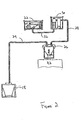
- the recovery system 10 removes excess proppant 14 from fluid used in an oil and gas well and recovers the excess proppant 14 for reuse in future operations. It should be appreciated that the system 10 can be used with any type of proppant material.
- the recovery system 10 separates the excess proppant 14 from the well fluid on a drilling platform "A".
- the excess proppant 14 and any residual fluid falls via gravity from solid separators 12 (e.g. shale shakers) into a material trough 15 with a chute 16.
- the proppant 14 falls through the trough chute 16 into a materials collection tank 18 that has an access opening 20.
- the recovery system 10 includes a compressed air blower (not shown) to assist the proppant 14 and any residual fluid through the chute 16 when the proppant 14 and residual fluid need to be broken up.
- a compressed air blower (not shown) to assist the proppant 14 and any residual fluid through the chute 16 when the proppant 14 and residual fluid need to be broken up.
- U.S. Patent No. 6,179,070 provides an example of a materials collection tank that can be used with the present invention and is hereby incorporated herein by reference for all purposes.
- a crane (not shown) then transports the materials collection tank 18 onto a processing boat "B". It should be appreciated by those skilled in the art that any suitable transportation means may be used to transport the materials collection tank 18.
- a blower 22 is in fluid communication with the materials collection tank 18 via a vacuum line 24 from the materials collection tank to a hopper 26, a vacuum line 28 from the hopper 26 to a drop tank 30, and a vacuum line 32 from the drop tank 30 to the blower 22.
- the blower 22 thus forms a vacuum within the materials collection tank 18 interior to transport the proppant 14 through the vacuum line 24 for discharge into the hopper 26.
- Valve 34 operates to open and close the discharge 40 of the hopper 26. Initially, the valve 34 is closed while the hopper 26 is filled with the proppant 14. When the hopper 26 is full, the valve 34 is opened to discharge the proppant 14 from the hopper 26 into a holding tank 42 for processing and reuse. The proppant 14 is thus separated from the vacuum line 24 at the hopper 26 before the proppant 14 can enter the blower 28. In addition, the drop tank 30 is also located along the vacuum line 28 between the hopper 26 and the blower 22 to collect any remaining proppant 14 in the vacuum line 28 before they reach the blower 22.
- the recovery system 10 recycles the proppant 14 in a manner that saves cost by providing an efficient recycling system.
- the recovery system 10 is also capable of operating entirely on-site without having to transport the excess proppant 14 off-site for processing.
- Patents describing transportation systems for wellbore solids include U.S. Patent Nos.: 5,402,857 ; 5,564,509 ; 5,839,521 ; 5,842,529 ; 5,913,372 ; 5,971,084 ; 6,009,959 ; 6,179,070B1 ; 6,179,071B1 ; and 6,213,227B1 .
- FIGURES 5-8 there is shown a proppant recovery system 110 constructed in accordance with an alternative embodiment.
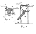
- the alternative embodiment proppant recovery system 110 of FIGURES 5-8 is similar in overall layout to the preferred embodiment recovery system 10. The difference is that instead of a single hopper 26, the suction line 24 from the materials collection tank (not shown) communicates with an upper hopper 126. Instead of being a single hopper, however, the hopper 126 is an upper hopper positioned above a lower hopper 127. The upper hopper 126 is still subjected to the vacuum applied by the blower (not shown) through the vacuum line 128 from the upper hopper 126 to the drop tank (not shown) and the vacuum line (not shown) from the drop tank to the blower.
- the proppant recovery system 110 represents a double hopper 126, 127 arrangement that replaces the single hopper 26 of recovery system 10.
- valves 134, 136 control the flow of the proppant 14 between the upper hopper 126 and the lower hopper 127.
- the valves 134, 136 also control the flow of the proppant from the lower hopper 127 to discharge 140 and then to holding tank 142.
- a user controls the valves 134, 136 using a control panel 146 and pneumatic or hydraulic controllers (commercially available) to direct flow from the upper hopper 126 to the lower hopper 127, and then to the holding tank 142.
- Valves 134, 136 can be pneumatic actuated flex-gate knife valves, for example, manufactured by Red Valve Company, Inc. of Pittsburgh, Pennsylvania, USA.
- the upper valve 134 is initially closed ( FIGURE 5 ) so that suction lines 124, 128 begin filling the hopper 126.
- the valve 134 opens while the lower valve 136 remains closed ( FIGURE 6 ).
- both of the hoppers 126, 127 are subjected to a vacuum.
- the vacuum does not prevent the proppant 14 collected in the upper hopper 126 from falling through the valve 134 and into the lower hopper 127.
- This transfer of the proppant 14 from the upper hopper 126 to the lower hopper 127 is shown in FIGURE 6 .
- the valve 136 remains closed as shown in FIGURE 6 . This closure of the valve 136 ensures that the vacuum is maintained on the interiors of both of the hoppers 126, 127. Otherwise, if the valve 136 were opened, the vacuum would be lost.
- the valve 134 is closed so that the valve 136 can be opened.
- the upper valve 134 is in its closed position to preserve the vacuum within the upper hopper 126.
- the valve 136 can then be opened ( FIGURE 8 ) so that the proppant 14 within the lower hopper 127 can be discharged into the discharge 140 and then into the holding tank 142.
- the proppant 14 can then be held in the holding tank 142 for treatment and reuse.
- the valving arrangement maintains vacuum within the upper hopper 126 at all times to provide a continuous vacuum operation.
Landscapes
- Engineering & Computer Science (AREA)
- Geology (AREA)
- Life Sciences & Earth Sciences (AREA)
- Mining & Mineral Resources (AREA)
- Environmental & Geological Engineering (AREA)
- Geochemistry & Mineralogy (AREA)
- Fluid Mechanics (AREA)
- General Life Sciences & Earth Sciences (AREA)
- Physics & Mathematics (AREA)
- Mechanical Engineering (AREA)
- Separation, Recovery Or Treatment Of Waste Materials Containing Plastics (AREA)
- Addition Polymer Or Copolymer, Post-Treatments, Or Chemical Modifications (AREA)
- Organic Low-Molecular-Weight Compounds And Preparation Thereof (AREA)
- Processing Of Solid Wastes (AREA)
- Pipe Accessories (AREA)
- Earth Drilling (AREA)
- Supports For Pipes And Cables (AREA)
- Exposure Of Semiconductors, Excluding Electron Or Ion Beam Exposure (AREA)
- Exposure And Positioning Against Photoresist Photosensitive Materials (AREA)
Claims (11)
- Verfahren zur Rückführung des Stützmittels (14) aus einer Flüssigkeit, die in einem Offshore-Erdöl- und Erdgasbohrloch verwendet wird, umfassend:Abtrennen des Stützmittels (14) von zumindest im Wesentlichen der gesamten Bohrlochflüssigkeit,Transportieren des abgetrennten Stützmittels (14) zu einem Offshore-Bereich zur Rückgewinnung des Stützmittels,Behandeln des abgetrennten Stützmittels (14) im Offshore-Bereich zur Rückgewinnung des Stützmittels, ohne dass das überschüssige Stützmittel (14) nach außerhalb transportiert werden muss, undWiederverwenden des behandelten Stützmittels (14) in einem Offshore-Erdöl- und Erdgas-Arbeitsfeld.
- Verfahren nach Anspruch 1, wobei der Transport des abgetrennten Stützmittels (14) zum Offshore-Bereich zur Rückgewinnung des Stützmittels zudem das Transportieren des abgetrennten Stützmittels (14) zu einem Materialsammelbehälter (18) und das Transportieren des Materialsammelbehälters (18) zum Offshore-Bereich zur Rückgewinnung des Stützmittels umfasst.
- Verfahren nach Anspruch 2, ferner umfassend den Transport des abgetrennten Stützmittels (14) vom Materialsammelbehälter (18) zu einem Trichter (26) und das Entleeren des abgetrennten Stützmittels (14) aus dem Trichter (26) in einen Vorratsbehälter (42).
- Verfahren nach Anspruch 3, wobei der Transport des abgetrennten Stützmittels (14) vom Materialsammelbehälter (18) zum Trichter (26) ferner das Erzeugen eines Vakuums im Trichter (26) mit einem Gebläse (22) umfasst, wobei das Gebläse (22) über eine Flüssigkeit mit dem Trichter (26) in Verbindung steht und das abgetrennte Stützmittel (14) mit einer Saugleitung (24, 28, 32) aus dem Materialvorratsbehälter (18) absaugt.
- Verfahren nach Anspruch 4, ferner umfassend den Transport des abgetrennten Stützmittels (14) zu einem zweiten Trichter (127) und das Befüllen und Leeren der beiden Trichter (126, 127) in abwechselnder Reihenfolge.
- Verfahren nach Anspruch 5, ferner umfassend das Trennen der beiden Trichter (126, 127) voneinander mit einem Ventilelement (134).
- Verfahren nach einem der Ansprüche 4 oder 5, ferner umfassend das Entnehmen des abgetrennten Stützmittels (14) aus der Saugleitung (24) am Trichter (26).
- Verfahren nach Anspruch 5, wobei die beiden Trichter (126, 127) senkrecht einer auf dem anderen angeordnet sind, sodass das abgetrennte Stützmittel (14) durch die Schwerkraft von dem Trichter (126) zu dem zweiten Trichter (127) strömen kann.
- Verfahren nach Anspruch 8, ferner umfassend das wirksame Zuordnen mindestens eines Ventils (134, 136) zu den beiden Trichtern (126, 127), um im Trichter (126) ein Vakuum aufrechtzuerhalten, wenn das abgetrennte Stützmittel (14) durch die Schwerkraft von dem Trichter (126) zu dem zweiten Trichter (127) oder von dem zweiten Trichter (127) zum Vorratsbehälter (142) strömt, sodass das abgetrennte Stützmittel (14) kontinuierlich aus dem Materialsammelbehälter (18) transportiert werden kann.
- Verfahren nach einem der Ansprüche 4 oder 5, ferner umfassend die Verwendung eines Krans für den Transport des Materialsammelbehälters (18) zum Offshore-Bereich zur Rückgewinnung des Stützmittels.
- Verfahren nach einem der Ansprüche 4 oder 5, wobei der Offshore-Bereich zur Rückgewinnung des Stützmittels ein Offshore-Schiff umfasst.
Applications Claiming Priority (5)
| Application Number | Priority Date | Filing Date | Title |
|---|---|---|---|
| US284125 | 1988-12-14 | ||
| US33624601P | 2001-11-02 | 2001-11-02 | |
| US336246P | 2001-11-02 | ||
| US10/284,125 US7040418B2 (en) | 2001-11-02 | 2002-10-30 | Proppant recovery system |
| PCT/US2002/034992 WO2003040514A2 (en) | 2001-11-02 | 2002-10-31 | Proppant recovery system |
Publications (3)
| Publication Number | Publication Date |
|---|---|
| EP1454028A2 EP1454028A2 (de) | 2004-09-08 |
| EP1454028A4 EP1454028A4 (de) | 2006-02-22 |
| EP1454028B1 true EP1454028B1 (de) | 2008-03-26 |
Family
ID=26962422
Family Applications (1)
| Application Number | Title | Priority Date | Filing Date |
|---|---|---|---|
| EP02802816A Expired - Lifetime EP1454028B1 (de) | 2001-11-02 | 2002-10-31 | System zur stützmittelrückgewinnung |
Country Status (10)
| Country | Link |
|---|---|
| US (1) | US7040418B2 (de) |
| EP (1) | EP1454028B1 (de) |
| AT (1) | ATE390538T1 (de) |
| AU (1) | AU2002363472A1 (de) |
| CA (1) | CA2466096C (de) |
| DE (1) | DE60225836T2 (de) |
| DK (1) | DK1454028T3 (de) |
| MX (1) | MXPA04004150A (de) |
| NO (1) | NO335592B1 (de) |
| WO (1) | WO2003040514A2 (de) |
Families Citing this family (18)
| Publication number | Priority date | Publication date | Assignee | Title |
|---|---|---|---|---|
| NO327355B1 (no) | 2005-08-25 | 2009-06-15 | Etec As | Anordning og fremgangsmate ved fragmentering av harde partikler. |
| EA021969B1 (ru) * | 2008-09-05 | 2015-10-30 | Шлюмбергер Норге Ас | Система и способ для транспортировки расклинивающих наполнителей |
| WO2011036556A2 (en) * | 2009-09-25 | 2011-03-31 | Schlumberger Norge As | Multiple process service vessel |
| US9845427B2 (en) | 2009-10-20 | 2017-12-19 | Self-Suspending Proppant Llc | Proppants for hydraulic fracturing technologies |
| US9868896B2 (en) | 2011-08-31 | 2018-01-16 | Self-Suspending Proppant Llc | Self-suspending proppants for hydraulic fracturing |
| MX365956B (es) | 2011-08-31 | 2019-06-18 | Self Suspending Proppant Llc | Agentes de apuntalamiento de auto-suspension para fracturacion hidraulica. |
| US20140000891A1 (en) | 2012-06-21 | 2014-01-02 | Self-Suspending Proppant Llc | Self-suspending proppants for hydraulic fracturing |
| US9297244B2 (en) | 2011-08-31 | 2016-03-29 | Self-Suspending Proppant Llc | Self-suspending proppants for hydraulic fracturing comprising a coating of hydrogel-forming polymer |
| US20140097182A1 (en) * | 2012-10-10 | 2014-04-10 | SandCan Inc. | Intermodal container having a resilient liner |
| WO2014011544A1 (en) * | 2012-07-09 | 2014-01-16 | M-I L.L.C. | Process for recovery of oleaginous fluids from wellbore fluids |
| US8424784B1 (en) * | 2012-07-27 | 2013-04-23 | MBJ Water Partners | Fracture water treatment method and system |
| US9896918B2 (en) | 2012-07-27 | 2018-02-20 | Mbl Water Partners, Llc | Use of ionized water in hydraulic fracturing |
| US20140027386A1 (en) | 2012-07-27 | 2014-01-30 | MBJ Water Partners | Fracture Water Treatment Method and System |
| GB2527479B (en) | 2013-04-26 | 2020-10-14 | Desbarats Andrew | A proppant immobilized enzyme and a viscofied fracture fluid |
| US9932521B2 (en) | 2014-03-05 | 2018-04-03 | Self-Suspending Proppant, Llc | Calcium ion tolerant self-suspending proppants |
| US11713415B2 (en) | 2018-11-21 | 2023-08-01 | Covia Solutions Inc. | Salt-tolerant self-suspending proppants made without extrusion |
| US11530944B1 (en) | 2019-02-28 | 2022-12-20 | Covenant Testing Technologies, Llc | Well fluid management systems and methods |
| US11739599B2 (en) * | 2020-10-21 | 2023-08-29 | BKG Industries, LLC | Proppant recovery unit |
Family Cites Families (16)
| Publication number | Priority date | Publication date | Assignee | Title |
|---|---|---|---|---|
| US4126181A (en) * | 1977-06-20 | 1978-11-21 | Palmer Engineering Company Ltd. | Method and apparatus for formation fracturing with foam having greater proppant concentration |
| US4183813A (en) * | 1978-11-15 | 1980-01-15 | Palmer Engineering Company Ltd. | Mixture concentrator |
| DK155781C (da) * | 1982-01-07 | 1989-10-09 | Niro Atomizer As | Fremgangsmaade til fremstilling af sintrede smaakugler af bauxit eller bauxitholdig bjergart, samt middel til udoevelse af fremgangsmaaden |
| CA1151527A (en) * | 1980-11-06 | 1983-08-09 | Ronald S. Bullen | Proppant concentrator |
| US4486317A (en) * | 1981-01-16 | 1984-12-04 | E. I. Du Pont De Nemours And Company | Stabilization of thickened aqueous fluids |
| US5842529A (en) * | 1994-02-17 | 1998-12-01 | Dietzen; Gary H. | Oil and gas well cuttings disposal system |
| US6009959A (en) * | 1994-02-17 | 2000-01-04 | M-I L.L.C. | Oil and gas well cuttings disposal system with continuous vacuum operation for sequentially filling disposal tanks |
| US5402857A (en) * | 1994-02-17 | 1995-04-04 | Dietzen; Gary H. | Oil and gas well cuttings disposal system |
| US5971084A (en) * | 1994-02-17 | 1999-10-26 | M-I L.L.C. | Cuttings tank apparatus |
| US6213227B1 (en) * | 1994-02-17 | 2001-04-10 | M-I, L.L.C. | Oil and gas well cuttings disposal system with continous vacuum operation for sequentially filling disposal tanks |
| US5839521A (en) * | 1994-02-17 | 1998-11-24 | Dietzen; Gary H. | Oil and gas well cuttings disposal system |
| US6179071B1 (en) * | 1994-02-17 | 2001-01-30 | M-I L.L.C. | Method and apparatus for handling and disposal of oil and gas well drill cuttings |
| US6179070B1 (en) * | 1994-02-17 | 2001-01-30 | M-I L.L.C. | Vacuum tank for use in handling oil and gas well cuttings |
| US5913372A (en) * | 1994-02-17 | 1999-06-22 | M-L, L.L.C. | Oil and gas well cuttings disposal system with continuous vacuum operation for sequentially filling disposal tanks |
| US6419019B1 (en) * | 1998-11-19 | 2002-07-16 | Schlumberger Technology Corporation | Method to remove particulate matter from a wellbore using translocating fibers and/or platelets |
| AU2003219848A1 (en) * | 2002-02-22 | 2003-09-09 | Flotek Indutries, Inc. | Mobile blending apparatus |
-
2002
- 2002-10-30 US US10/284,125 patent/US7040418B2/en not_active Expired - Fee Related
- 2002-10-31 EP EP02802816A patent/EP1454028B1/de not_active Expired - Lifetime
- 2002-10-31 MX MXPA04004150A patent/MXPA04004150A/es active IP Right Grant
- 2002-10-31 DK DK02802816T patent/DK1454028T3/da active
- 2002-10-31 AT AT02802816T patent/ATE390538T1/de not_active IP Right Cessation
- 2002-10-31 WO PCT/US2002/034992 patent/WO2003040514A2/en not_active Ceased
- 2002-10-31 DE DE60225836T patent/DE60225836T2/de not_active Expired - Lifetime
- 2002-10-31 AU AU2002363472A patent/AU2002363472A1/en not_active Abandoned
- 2002-10-31 CA CA002466096A patent/CA2466096C/en not_active Expired - Fee Related
-
2004
- 2004-05-03 NO NO20041794A patent/NO335592B1/no not_active IP Right Cessation
Also Published As
| Publication number | Publication date |
|---|---|
| WO2003040514A3 (en) | 2004-06-24 |
| US7040418B2 (en) | 2006-05-09 |
| EP1454028A4 (de) | 2006-02-22 |
| MXPA04004150A (es) | 2005-12-12 |
| EP1454028A2 (de) | 2004-09-08 |
| ATE390538T1 (de) | 2008-04-15 |
| NO20041794L (no) | 2004-06-30 |
| CA2466096A1 (en) | 2003-05-15 |
| US20030106713A1 (en) | 2003-06-12 |
| NO335592B1 (no) | 2015-01-12 |
| DK1454028T3 (da) | 2008-07-21 |
| WO2003040514A2 (en) | 2003-05-15 |
| DE60225836D1 (de) | 2008-05-08 |
| AU2002363472A1 (en) | 2003-05-19 |
| DE60225836T2 (de) | 2009-04-09 |
| CA2466096C (en) | 2008-05-20 |
Similar Documents
| Publication | Publication Date | Title |
|---|---|---|
| US7040418B2 (en) | Proppant recovery system | |
| CA2256382C (en) | Oil and gas well cuttings disposal system with continuous vacuum operation for sequentially filling disposal tanks | |
| US6213227B1 (en) | Oil and gas well cuttings disposal system with continous vacuum operation for sequentially filling disposal tanks | |
| CA2505628C (en) | Apparatus and method for moving drilled cuttings | |
| NO311232B1 (no) | Fremgangsmåte for fjerning av borekaks fra en boreplattform | |
| US6009959A (en) | Oil and gas well cuttings disposal system with continuous vacuum operation for sequentially filling disposal tanks | |
| CA2321417C (en) | Oil and gas well cuttings disposal system with continuous vacuum operation for sequentially filling disposal tanks | |
| NO335252B1 (no) | Apparat og fremgangsmåte for flytting av borekaks | |
| EP2052127A1 (de) | Verfahren und vorrichtung zur vorbereitung von bohrklein zur reinjektion in ein bohrloch | |
| US8276686B2 (en) | Vacuum assisted drill cuttings dryer and handling apparatus | |
| NO326351B1 (no) | Apparat og fremgangsmate for overforing av torr borekaks fra olje og gassbronner | |
| EP2310619B1 (de) | Bohrkleintransfersystem | |
| US10227837B2 (en) | Drilling waste treatment | |
| WO2021246876A1 (en) | Method for real-time measuring weight and volume of discharging particulate material generated in oil and gas exploration and production operations | |
| WO2007085813A1 (en) | Method for processing drilling cuttings in an oil recovery operation | |
| NO20161820A1 (en) | Integrated automatic tank cleaning skip | |
| CA2581682C (en) | Apparatus and method for moving drilled cuttings | |
| GB2369135A (en) | System for collection, transportation and delivery of drill cuttings |
Legal Events
| Date | Code | Title | Description |
|---|---|---|---|
| PUAI | Public reference made under article 153(3) epc to a published international application that has entered the european phase |
Free format text: ORIGINAL CODE: 0009012 |
|
| 17P | Request for examination filed |
Effective date: 20040430 |
|
| AK | Designated contracting states |
Kind code of ref document: A2 Designated state(s): AT BE BG CH CY CZ DE DK EE ES FI FR GB GR IE IT LI LU MC NL PT SE SK TR |
|
| AX | Request for extension of the european patent |
Extension state: AL LT LV MK RO SI |
|
| RIN1 | Information on inventor provided before grant (corrected) |
Inventor name: SLATER, MARTIN Inventor name: HILBIG, NICHOLAS Inventor name: CAMPBELL, BRIAN Inventor name: PEREZ, DANIEL Inventor name: DIETZEN, GARY |
|
| A4 | Supplementary search report drawn up and despatched |
Effective date: 20060111 |
|
| RIC1 | Information provided on ipc code assigned before grant |
Ipc: E21B 1/00 20060101AFI20030520BHEP Ipc: E21B 41/00 20060101ALI20060104BHEP Ipc: E21B 21/01 20060101ALI20060104BHEP |
|
| 17Q | First examination report despatched |
Effective date: 20060907 |
|
| GRAP | Despatch of communication of intention to grant a patent |
Free format text: ORIGINAL CODE: EPIDOSNIGR1 |
|
| GRAS | Grant fee paid |
Free format text: ORIGINAL CODE: EPIDOSNIGR3 |
|
| GRAA | (expected) grant |
Free format text: ORIGINAL CODE: 0009210 |
|
| AK | Designated contracting states |
Kind code of ref document: B1 Designated state(s): AT BE BG CH CY CZ DE DK EE ES FI FR GB GR IE IT LI LU MC NL PT SE SK TR |
|
| REG | Reference to a national code |
Ref country code: GB Ref legal event code: FG4D |
|
| REG | Reference to a national code |
Ref country code: IE Ref legal event code: FG4D Ref country code: CH Ref legal event code: EP |
|
| REF | Corresponds to: |
Ref document number: 60225836 Country of ref document: DE Date of ref document: 20080508 Kind code of ref document: P |
|
| REG | Reference to a national code |
Ref country code: DK Ref legal event code: T3 |
|
| PG25 | Lapsed in a contracting state [announced via postgrant information from national office to epo] |
Ref country code: FI Free format text: LAPSE BECAUSE OF FAILURE TO SUBMIT A TRANSLATION OF THE DESCRIPTION OR TO PAY THE FEE WITHIN THE PRESCRIBED TIME-LIMIT Effective date: 20080326 |
|
| PG25 | Lapsed in a contracting state [announced via postgrant information from national office to epo] |
Ref country code: AT Free format text: LAPSE BECAUSE OF FAILURE TO SUBMIT A TRANSLATION OF THE DESCRIPTION OR TO PAY THE FEE WITHIN THE PRESCRIBED TIME-LIMIT Effective date: 20080326 |
|
| PG25 | Lapsed in a contracting state [announced via postgrant information from national office to epo] |
Ref country code: BE Free format text: LAPSE BECAUSE OF FAILURE TO SUBMIT A TRANSLATION OF THE DESCRIPTION OR TO PAY THE FEE WITHIN THE PRESCRIBED TIME-LIMIT Effective date: 20080326 |
|
| PG25 | Lapsed in a contracting state [announced via postgrant information from national office to epo] |
Ref country code: PT Free format text: LAPSE BECAUSE OF FAILURE TO SUBMIT A TRANSLATION OF THE DESCRIPTION OR TO PAY THE FEE WITHIN THE PRESCRIBED TIME-LIMIT Effective date: 20080901 Ref country code: SK Free format text: LAPSE BECAUSE OF FAILURE TO SUBMIT A TRANSLATION OF THE DESCRIPTION OR TO PAY THE FEE WITHIN THE PRESCRIBED TIME-LIMIT Effective date: 20080326 Ref country code: SE Free format text: LAPSE BECAUSE OF FAILURE TO SUBMIT A TRANSLATION OF THE DESCRIPTION OR TO PAY THE FEE WITHIN THE PRESCRIBED TIME-LIMIT Effective date: 20080626 Ref country code: ES Free format text: LAPSE BECAUSE OF FAILURE TO SUBMIT A TRANSLATION OF THE DESCRIPTION OR TO PAY THE FEE WITHIN THE PRESCRIBED TIME-LIMIT Effective date: 20080707 Ref country code: CZ Free format text: LAPSE BECAUSE OF FAILURE TO SUBMIT A TRANSLATION OF THE DESCRIPTION OR TO PAY THE FEE WITHIN THE PRESCRIBED TIME-LIMIT Effective date: 20080326 |
|
| EN | Fr: translation not filed | ||
| PLBE | No opposition filed within time limit |
Free format text: ORIGINAL CODE: 0009261 |
|
| STAA | Information on the status of an ep patent application or granted ep patent |
Free format text: STATUS: NO OPPOSITION FILED WITHIN TIME LIMIT |
|
| 26N | No opposition filed |
Effective date: 20081230 |
|
| PGFP | Annual fee paid to national office [announced via postgrant information from national office to epo] |
Ref country code: IT Payment date: 20081016 Year of fee payment: 7 |
|
| PG25 | Lapsed in a contracting state [announced via postgrant information from national office to epo] |
Ref country code: EE Free format text: LAPSE BECAUSE OF FAILURE TO SUBMIT A TRANSLATION OF THE DESCRIPTION OR TO PAY THE FEE WITHIN THE PRESCRIBED TIME-LIMIT Effective date: 20080326 Ref country code: FR Free format text: LAPSE BECAUSE OF FAILURE TO SUBMIT A TRANSLATION OF THE DESCRIPTION OR TO PAY THE FEE WITHIN THE PRESCRIBED TIME-LIMIT Effective date: 20090116 Ref country code: BG Free format text: LAPSE BECAUSE OF FAILURE TO SUBMIT A TRANSLATION OF THE DESCRIPTION OR TO PAY THE FEE WITHIN THE PRESCRIBED TIME-LIMIT Effective date: 20080626 |
|
| PG25 | Lapsed in a contracting state [announced via postgrant information from national office to epo] |
Ref country code: MC Free format text: LAPSE BECAUSE OF NON-PAYMENT OF DUE FEES Effective date: 20081031 |
|
| REG | Reference to a national code |
Ref country code: CH Ref legal event code: PL |
|
| PG25 | Lapsed in a contracting state [announced via postgrant information from national office to epo] |
Ref country code: CY Free format text: LAPSE BECAUSE OF FAILURE TO SUBMIT A TRANSLATION OF THE DESCRIPTION OR TO PAY THE FEE WITHIN THE PRESCRIBED TIME-LIMIT Effective date: 20080326 |
|
| PG25 | Lapsed in a contracting state [announced via postgrant information from national office to epo] |
Ref country code: CH Free format text: LAPSE BECAUSE OF NON-PAYMENT OF DUE FEES Effective date: 20081031 Ref country code: IE Free format text: LAPSE BECAUSE OF NON-PAYMENT OF DUE FEES Effective date: 20081031 Ref country code: LI Free format text: LAPSE BECAUSE OF NON-PAYMENT OF DUE FEES Effective date: 20081031 |
|
| PG25 | Lapsed in a contracting state [announced via postgrant information from national office to epo] |
Ref country code: LU Free format text: LAPSE BECAUSE OF NON-PAYMENT OF DUE FEES Effective date: 20081031 |
|
| PG25 | Lapsed in a contracting state [announced via postgrant information from national office to epo] |
Ref country code: TR Free format text: LAPSE BECAUSE OF FAILURE TO SUBMIT A TRANSLATION OF THE DESCRIPTION OR TO PAY THE FEE WITHIN THE PRESCRIBED TIME-LIMIT Effective date: 20080326 |
|
| PG25 | Lapsed in a contracting state [announced via postgrant information from national office to epo] |
Ref country code: GR Free format text: LAPSE BECAUSE OF FAILURE TO SUBMIT A TRANSLATION OF THE DESCRIPTION OR TO PAY THE FEE WITHIN THE PRESCRIBED TIME-LIMIT Effective date: 20080627 |
|
| PG25 | Lapsed in a contracting state [announced via postgrant information from national office to epo] |
Ref country code: IT Free format text: LAPSE BECAUSE OF NON-PAYMENT OF DUE FEES Effective date: 20091031 |
|
| PGFP | Annual fee paid to national office [announced via postgrant information from national office to epo] |
Ref country code: DK Payment date: 20141010 Year of fee payment: 13 |
|
| PGFP | Annual fee paid to national office [announced via postgrant information from national office to epo] |
Ref country code: DE Payment date: 20141029 Year of fee payment: 13 Ref country code: GB Payment date: 20141029 Year of fee payment: 13 |
|
| PGFP | Annual fee paid to national office [announced via postgrant information from national office to epo] |
Ref country code: NL Payment date: 20141010 Year of fee payment: 13 |
|
| REG | Reference to a national code |
Ref country code: DE Ref legal event code: R119 Ref document number: 60225836 Country of ref document: DE |
|
| REG | Reference to a national code |
Ref country code: DK Ref legal event code: EBP Effective date: 20151031 |
|
| GBPC | Gb: european patent ceased through non-payment of renewal fee |
Effective date: 20151031 |
|
| REG | Reference to a national code |
Ref country code: NL Ref legal event code: MM Effective date: 20151101 |
|
| PG25 | Lapsed in a contracting state [announced via postgrant information from national office to epo] |
Ref country code: GB Free format text: LAPSE BECAUSE OF NON-PAYMENT OF DUE FEES Effective date: 20151031 Ref country code: DE Free format text: LAPSE BECAUSE OF NON-PAYMENT OF DUE FEES Effective date: 20160503 |
|
| PG25 | Lapsed in a contracting state [announced via postgrant information from national office to epo] |
Ref country code: NL Free format text: LAPSE BECAUSE OF NON-PAYMENT OF DUE FEES Effective date: 20151101 |
|
| PG25 | Lapsed in a contracting state [announced via postgrant information from national office to epo] |
Ref country code: DK Free format text: LAPSE BECAUSE OF NON-PAYMENT OF DUE FEES Effective date: 20151031 |
|
| P01 | Opt-out of the competence of the unified patent court (upc) registered |
Effective date: 20231216 |