EP1454588A2 - Bobine de transmission de force pour instrument endoscopique flexible et outil de traitement médical muni d'une telle bobine - Google Patents
Bobine de transmission de force pour instrument endoscopique flexible et outil de traitement médical muni d'une telle bobine Download PDFInfo
- Publication number
- EP1454588A2 EP1454588A2 EP04004705A EP04004705A EP1454588A2 EP 1454588 A2 EP1454588 A2 EP 1454588A2 EP 04004705 A EP04004705 A EP 04004705A EP 04004705 A EP04004705 A EP 04004705A EP 1454588 A2 EP1454588 A2 EP 1454588A2
- Authority
- EP
- European Patent Office
- Prior art keywords
- axis
- close
- wire
- wound coil
- section
- Prior art date
- Legal status (The legal status is an assumption and is not a legal conclusion. Google has not performed a legal analysis and makes no representation as to the accuracy of the status listed.)
- Granted
Links
- 230000005540 biological transmission Effects 0.000 title abstract description 36
- 230000000717 retained effect Effects 0.000 claims 1
- 238000004804 winding Methods 0.000 abstract description 32
- 238000005452 bending Methods 0.000 description 22
- 239000012636 effector Substances 0.000 description 13
- 238000004519 manufacturing process Methods 0.000 description 11
- 239000000463 material Substances 0.000 description 11
- 229910052751 metal Inorganic materials 0.000 description 8
- 239000002184 metal Substances 0.000 description 8
- 230000003247 decreasing effect Effects 0.000 description 7
- 230000000694 effects Effects 0.000 description 6
- 238000003780 insertion Methods 0.000 description 6
- 230000037431 insertion Effects 0.000 description 6
- 238000009826 distribution Methods 0.000 description 5
- 210000000683 abdominal cavity Anatomy 0.000 description 4
- 238000009825 accumulation Methods 0.000 description 4
- 208000037062 Polyps Diseases 0.000 description 3
- 230000002950 deficient Effects 0.000 description 2
- 238000000034 method Methods 0.000 description 2
- 230000008569 process Effects 0.000 description 2
- 230000009471 action Effects 0.000 description 1
- 238000001574 biopsy Methods 0.000 description 1
- 230000008859 change Effects 0.000 description 1
- 230000006835 compression Effects 0.000 description 1
- 238000007906 compression Methods 0.000 description 1
- 230000008878 coupling Effects 0.000 description 1
- 238000010168 coupling process Methods 0.000 description 1
- 238000005859 coupling reaction Methods 0.000 description 1
- 230000006866 deterioration Effects 0.000 description 1
- 229910001000 nickel titanium Inorganic materials 0.000 description 1
- 230000036285 pathological change Effects 0.000 description 1
- 231100000915 pathological change Toxicity 0.000 description 1
- 230000002093 peripheral effect Effects 0.000 description 1
- 238000003825 pressing Methods 0.000 description 1
- 238000005096 rolling process Methods 0.000 description 1
- 229910001220 stainless steel Inorganic materials 0.000 description 1
- WFKWXMTUELFFGS-UHFFFAOYSA-N tungsten Chemical compound [W] WFKWXMTUELFFGS-UHFFFAOYSA-N 0.000 description 1
- 238000003466 welding Methods 0.000 description 1
Images








Classifications
-
- F—MECHANICAL ENGINEERING; LIGHTING; HEATING; WEAPONS; BLASTING
- F16—ENGINEERING ELEMENTS AND UNITS; GENERAL MEASURES FOR PRODUCING AND MAINTAINING EFFECTIVE FUNCTIONING OF MACHINES OR INSTALLATIONS; THERMAL INSULATION IN GENERAL
- F16C—SHAFTS; FLEXIBLE SHAFTS; ELEMENTS OR CRANKSHAFT MECHANISMS; ROTARY BODIES OTHER THAN GEARING ELEMENTS; BEARINGS
- F16C1/00—Flexible shafts; Mechanical means for transmitting movement in a flexible sheathing
- F16C1/02—Flexible shafts; Mechanical means for transmitting movement in a flexible sheathing for conveying rotary movements
-
- A—HUMAN NECESSITIES
- A61—MEDICAL OR VETERINARY SCIENCE; HYGIENE
- A61B—DIAGNOSIS; SURGERY; IDENTIFICATION
- A61B17/00—Surgical instruments, devices or methods
- A61B17/00234—Surgical instruments, devices or methods for minimally invasive surgery
-
- A—HUMAN NECESSITIES
- A61—MEDICAL OR VETERINARY SCIENCE; HYGIENE
- A61B—DIAGNOSIS; SURGERY; IDENTIFICATION
- A61B17/00—Surgical instruments, devices or methods
- A61B17/10—Surgical instruments, devices or methods for applying or removing wound clamps, e.g. containing only one clamp or staple; Wound clamp magazines
-
- A—HUMAN NECESSITIES
- A61—MEDICAL OR VETERINARY SCIENCE; HYGIENE
- A61B—DIAGNOSIS; SURGERY; IDENTIFICATION
- A61B17/00—Surgical instruments, devices or methods
- A61B17/32—Surgical cutting instruments
- A61B17/320016—Endoscopic cutting instruments, e.g. arthroscopes, resectoscopes
-
- A—HUMAN NECESSITIES
- A61—MEDICAL OR VETERINARY SCIENCE; HYGIENE
- A61B—DIAGNOSIS; SURGERY; IDENTIFICATION
- A61B17/00—Surgical instruments, devices or methods
- A61B17/12—Surgical instruments, devices or methods for ligaturing or otherwise compressing tubular parts of the body, e.g. blood vessels or umbilical cord
- A61B17/128—Surgical instruments, devices or methods for ligaturing or otherwise compressing tubular parts of the body, e.g. blood vessels or umbilical cord for applying or removing clamps or clips
- A61B17/1285—Surgical instruments, devices or methods for ligaturing or otherwise compressing tubular parts of the body, e.g. blood vessels or umbilical cord for applying or removing clamps or clips for minimally invasive surgery
-
- A—HUMAN NECESSITIES
- A61—MEDICAL OR VETERINARY SCIENCE; HYGIENE
- A61B—DIAGNOSIS; SURGERY; IDENTIFICATION
- A61B17/00—Surgical instruments, devices or methods
- A61B17/32—Surgical cutting instruments
- A61B17/3205—Excision instruments
- A61B17/32056—Surgical snare instruments
-
- A—HUMAN NECESSITIES
- A61—MEDICAL OR VETERINARY SCIENCE; HYGIENE
- A61B—DIAGNOSIS; SURGERY; IDENTIFICATION
- A61B18/00—Surgical instruments, devices or methods for transferring non-mechanical forms of energy to or from the body
- A61B18/04—Surgical instruments, devices or methods for transferring non-mechanical forms of energy to or from the body by heating
- A61B18/12—Surgical instruments, devices or methods for transferring non-mechanical forms of energy to or from the body by heating by passing a current through the tissue to be heated, e.g. high-frequency current
- A61B18/14—Probes or electrodes therefor
- A61B18/1492—Probes or electrodes therefor having a flexible, catheter-like structure, e.g. for heart ablation
-
- A—HUMAN NECESSITIES
- A61—MEDICAL OR VETERINARY SCIENCE; HYGIENE
- A61B—DIAGNOSIS; SURGERY; IDENTIFICATION
- A61B17/00—Surgical instruments, devices or methods
- A61B17/28—Surgical forceps
- A61B17/29—Forceps for use in minimally invasive surgery
- A61B2017/2901—Details of shaft
- A61B2017/2905—Details of shaft flexible
-
- A—HUMAN NECESSITIES
- A61—MEDICAL OR VETERINARY SCIENCE; HYGIENE
- A61B—DIAGNOSIS; SURGERY; IDENTIFICATION
- A61B18/00—Surgical instruments, devices or methods for transferring non-mechanical forms of energy to or from the body
- A61B18/04—Surgical instruments, devices or methods for transferring non-mechanical forms of energy to or from the body by heating
- A61B18/12—Surgical instruments, devices or methods for transferring non-mechanical forms of energy to or from the body by heating by passing a current through the tissue to be heated, e.g. high-frequency current
- A61B18/14—Probes or electrodes therefor
- A61B2018/1405—Electrodes having a specific shape
- A61B2018/1407—Loop
-
- F—MECHANICAL ENGINEERING; LIGHTING; HEATING; WEAPONS; BLASTING
- F16—ENGINEERING ELEMENTS AND UNITS; GENERAL MEASURES FOR PRODUCING AND MAINTAINING EFFECTIVE FUNCTIONING OF MACHINES OR INSTALLATIONS; THERMAL INSULATION IN GENERAL
- F16C—SHAFTS; FLEXIBLE SHAFTS; ELEMENTS OR CRANKSHAFT MECHANISMS; ROTARY BODIES OTHER THAN GEARING ELEMENTS; BEARINGS
- F16C2316/00—Apparatus in health or amusement
- F16C2316/10—Apparatus in health or amusement in medical appliances, e.g. in diagnosis, dentistry, instruments, prostheses, medical imaging appliances
Definitions
- the present invention relates to a close-wound coil formed by winding a wire spirally and closely over a predetermined length, and a medical treatment tool using the close-wound coil.
- a medical treatment tool inserted into a human body through an endoscope channel comprises a treatment section provided at a distal end, a control section provided at a proximal end, and a transmission member to transmit the operating force from the control section to the treatment section.
- the transmission member is inserted into an elongated channel extended in an endoscope which is inserted into a winding tubular abdominal cavity, and required not only to withstand bending and compressing but to transmit the operating force from the control section to the treatment section.
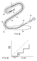
- FIG. 42 schematically illustrates an example of a conventional medical treatment tool having such a close-wound coil as a force transmission member.
- a medical treatment tool 100 comprises a treatment section 102 provided at a distal end, an operation section 106 provided at a proximal end, and a close-wound coil 104 which connects the operation section 106 and treatment section 102.
- An endoscope 200 to lead the medical treatment tool 100 into a human body is provided with an insertion part 202 to be inserted into a tubular cavity in the body, and a control section 206 at a proximal end.
- a channel 208 to insert the medical treatment tool 100 is formed in the insertion part 202.
- a bending section 204 that is bent by a control knob (not shown) provided in the control section 206 is provided.
- FIG. 43 shows schematically the rotation transmission performance of a conventional close-wound coil in the bent state shown in FIG. 42.
- a delay or skip unevenness
- the present invention has been made in order to solve the above problems. Accordingly, it is an object of the present invention to provide a close-wound coil having a good rotation transmission performance, and a medical treatment tool using the close-wound coil.
- a close-wound coil comprising a first predetermined axis, and a wire which is wound spirally and closely over a predetermined length around the first axis, and has a center axis extending in the length direction thereof.
- the wire has a section vertical to the center axis, a second axis passing across the center axis within the section and vertical to the first axis, and a third axis passing across the center axis within the section and vertical to the second axis.
- the wire has substantially the same flexural rigidity as that of a reference wire having a perfect circle section with a diameter of the longer one of section along the second axis and section along third axis and the torsional rigidity of the wire is lower than the torsional rigidity of the reference wire.
- a close-wound coil comprising a first predetermined axis, and a wire which is wound spirally and closely over a predetermined length around the first axis, and has a center axis extending in the length direction thereof.
- the wire has a section vertical to the center axis, a second axis passing across the center axis within the section and vertical to the first axis, and a third axis passing across the center axis within the section and vertical to the second axis.
- the section is formed to have the second moment of area concerning the second axis smaller than the second moment of area concerning the third axis.
- a close-wound coil comprising a first predetermined axis, and a wire which is wound spirally and closely over a predetermined length around the first axis, and has a center axis extending in the length direction thereof.
- the wire has a section vertical to the center axis, a second axis passing across the center axis within the section and vertical to the first axis, and a third axis passing across the center axis within the section and vertical to the second axis.
- the section is formed to have the dimension along the second axis larger than the dimension along the third axis.
- a medical treatment tool comprising a close-wound coil having a distal end and a proximal end.
- the close-wound coil comprising a first axis extending between the distal end and proximal end, and a wire which is wound spirally and closely over a predetermined length around the first axis, and has a center axis extending in the length direction.
- the wire has a section vertical to the center axis, a second axis passing across the center axis within the section and vertical to the first axis, and a third axis passing across the center axis within the section and vertical to the second axis.
- the medical treatment tool further comprising a rotation control section which is provided in the proximal end of the close-wound coil, for rotating the close-wound coil around the first axis, and a treatment section which is located closer to the distal end than the close-wound coil, and receives the rotation control force from the rotation control section through the close-wound coil.
- the wire has substantially the same flexural rigidity as that of a reference wire having a perfect circle section with a diameter of predetermined dimension, and the torsional rigidity of the wire is lower than the torsional rigidity of the reference wire.
- a medical treatment tool used in combination with a medical endoscope comprising a mantle tube, and a close-wound coil inserted into the mantle tube, the close-wound coil having a first axis extending between the distal end and proximal end, and a wire which is wound spirally and closely over a predetermined length around the first axis, and has a center axis extending in the length direction thereof.
- the wire has a section vertical to the center axis, a second axis passing across the center axis within the section and vertical to the first axis, and a third axis passing across the center axis within the section and vertical to the second axis.
- the medical treatment tool further comprises a control section for rotating the close-wound coil with respect to the mantle tube.
- the wire has substantially the same flexural rigidity as that of a reference wire having a perfect circle section with a predetermined dimension.
- the torsional rigidity of the wire is lower than the torsional rigidity of the reference wire.
- a treatment tool for an endoscope used in combination with a medical endoscope having a slender channel.
- the treatment tool for an endoscope comprises a close-wound coil which can be inserted into the channel.
- the close-wound coil comprises a first axis extending between the distal end and proximal end, and a wire which is wound spirally and closely over a predetermined length around the first axis, and has a center axis extending in the length direction thereof.
- the wire has a section vertical to the center axis, a second axis passing across the center axis within the section and vertical to the first axis, and a third axis passing across the center axis within the section and vertical to the second axis.
- the treatment tool further comprises a rotary part which is provided in the close-wound coil, and rotates the close-wound coil with respect to the channel.
- the wire has substantially the same flexural rigidity as that of a reference wire having a perfect circle section with a predetermined dimension, and the torsional rigidity of the wire is lower than the torsional rigidity of the reference wire.
- a close-wound coil having a good rotation transmission performance, and a medical treatment tool using the close-wound coil.
- the second cause of generating a delay between an input angle and an output angle is frictional resistance generated between an endoscope channel and a close-wound coil.
- a close-wound coil in the state that close-wound coil 4 is inserted into an endoscope channel 2, he close-wound coil 4 is pressed to contact to the inside surface of the channel 2, thereby generating frictional resistance.
- the contact pressure of the close-wound coil 4 to the channel 2 at a contact point P is small, and the frictional resistance is decreased.
- the flexural rigidity of the close-wound coil 4 is large, the contact pressure of the close-wound coil 4 to the channel 2 at the contact point P is large, and the frictional resistance is increased.
- the rotation transmission performance of a close-wound coil can be increased by increasing the torsional rigidity of a close-wound coil and decreasing the flexural rigidity of a close-wound coil.
- the torsional rigidity and flexural rigidity of a close-wound coil are originally considered to correspond to the torsional rigidity and flexural rigidity of a wire forming a close-wound coil. Namely, as shown in FIG. 2, considering the close-wound coil 10 formed by winding a wire 8 with a circular section spirally and closely over a predetermined length, the torsion of the close-wound coil 10 corresponds to the flex of the wire 8 as shown in FIGS. 3A and 3B. Concretely, when the close-wound coil 10 is twisted in the winding direction, the position of the wire 8 forming a curved beam is bent inward as shown in FIG. 3B.
- the close-wound coil 10 when the close-wound coil 10 is twisted in the direction opposite to the winding direction, the position of the wire 8 forming a curved beam is bent outward as shown in FIG. 3A. Therefore, the torsional rigidity of the close-wound coil 10 corresponds to the flexural rigidity of the wire 8 forming the close-wound coil 10.
- the flex of the close-wound coil 10 corresponds to the torsion of the wire 8 as shown in FIGS. 4A and 4B. Because, when the close-wound coil 10 is bent, the wire 8 is deformed and the adjacent windings are separated each other, to receive the force in the twisting direction. Therefore, the flexural rigidity of the close-wound coil 10 corresponds to the torsional rigidity of the wire 8 forming the close-wound coil 10.
- FIG. 4B shows the stress distribution in the wire 8 when the torsional torque acts on the wire 8 as shown in FIG. 4A.
- the conventional close-wound coil 10 does not easily satisfy the above conditions. Because, the wire 8 of the conventional close-wound coil 10 has a circular section, and if the outside diameter of the wire 8 is increased to improve the torsional rigidity of the close-wound coil 10, the flexural rigidity of the close-wound coil 10 is also increased. Therefore, when the wire 8 has a circular section, it is difficult to improve the rotation performance of the close-wound coil 10 merely by changing the outside diameter.
- the inventor of the present application considered all the above points, and as a result, found that the correlation between the second moment of area in the wire has a great concern to the above conditions under certain conditions. Further, the applicant of the present application also found that the above conditions are easily satisfied under certain conditions, even if the wire has a circular section.
- FIG. 5 to FIG. 7 show a first embodiment of the present invention.
- a close-wound coil 20 is formed by winding a wire 18 with a non-circular section spirally and closely over a predetermined length around a predetermined first axis O1.
- the wire 18 is formed so that in a section S vertical to a center axis O2 extending in the lengthwise direction of the wire, the second moment of area I 1 concerning a second axis O3 passing across a center axis O2 and vertical to the first axis O1 is smaller than the second moment of area I 2 concerning a third axis O4 passing across the center axis O2 of the section S and vertical to the second axis O3.
- the section S of the wire 18 is substantially rectangular where the dimension Y along the second axis O3 is larger than the dimension X along the third axis O4 (the vertical-to-horizontal ratio of the section S is larger than 1, and has an arc with a large curvature at both ends along the second axis O3).
- the close-wound coil 20 is formed in arrangement that the sections S of the adjacent windings of the wire 18 are closely contacted in the shorter radius direction (the state shown in FIG. 5).
- the above section shape of the wire 18 is formed at a low cost by rolling a wire with a circular section in the direction along the third axis O4, for example.
- the dimension of the section S of the wire 18 is set, so that the torsional rigidity becomes equivalent to (substantially identical to) that of a wire having a perfect circle section with a diameter d (hereinafter, this is referred to as a first reference wire).
- a first reference wire a wire having a perfect circle section with a diameter d.
- ⁇ 1 is a constant determined by Y/X.
- the torsion angle ⁇ when a torsional moment T is applied to a rod with the length L is:
- wire 18 in this embodiment a corrosion-proof material resistant to flexural deformation, tensile load and compressive load is preferable.
- a corrosion-proof material resistant to flexural deformation, tensile load and compressive load is preferable.
- stainless steel wire for a spring SUS304-WPB, SUS316-WPA, SUS301, SUS302-WPB, SUS631J1-WPC) defined by Japan Industrial Standard
- nickel-titanium alloy with super-elasticity
- piano wire oil tempered wire and tungsten wire.
- the wire 18 is formed so that the second moment of area I 2 concerning the third axis O4 is larger than the second moment of area I 1 concerning the second axis O3.
- the flexural rigidity of the wire 18 forming a bending beam (refer to FIGS. 6A and 6B showing the state that the bending force F1 is acted on the wire 18) in the direction along the second axis O3. Therefore, the torsional rigidity of the close-wound coil 20 can be increased compared with that of a conventional close-wound coil formed by a circular wire. As a result, the rotation transmission performance (rotation following performance) can be increased.
- the dimension of the section S of the wire 18 is set so that the torsional rigidity of the wire 18 is equivalent to the torsional rigidity of the first reference wire.
- FIGGS. 7A and 7B show the state that a twisting force F2 is acted on the wire 18. Therefore, the flexural rigidity of the close-wound coil 20 is equivalent to the corresponding flexural rigidity of a close-wound coil formed by the first reference wire having the above-mentioned circular section with a diameter d (hereinafter, referred to as a first reference close-wound coil).
- the torsional rigidity of the wire 18 is set equivalent to the torsional rigidity of the first reference wire, the flexural rigidity of the wire 18 is inevitably larger than that of the first reference wire.
- the second moment of area I L and I R are calculated
- the torsional rigidity is larger than that of the first reference close-wound coil, and the flexural rigidity is equivalent to that of the first reference close-wound coil. Therefore, the rotation transmission performance (rotation following performance) is increased to higher than the first reference close-wound coil.
- a wire has a circular section as in a conventionally, the wires 8 of the coil 10 contact at a point as shown in FIG. 8A, and when a strong compressive force F is acted on both ends while the coil 10 is being curved, the wires 8 are displaced and easily deformed permanently.
- FIG. 8B even if the section shape of the wire 8A is not circular but rectangular, when the dimension of the section in the horizontal direction (the length direction of the coil 10A) is longer than the dimension in the vertical direction, the wires 8A overlap in the radial direction, the coil length is contracted, and more serious deformation is caused. Thus, there arise a problem of causing permanent deformation more easily.
- the wires 18 contact in a face and hardly to displace (FIG. 8C). Further, since there is an allowance in the vertical length of the contact area of the wires 18, the wires 18 are hardly to overlap in the radial direction even if displayed by the same amount T as the conventional (refer to FIGS. 8B and 8C). Therefore, permanent deformation is difficult to occur, and the compression resistance is improved.
- an another highly flexible close-wound coil 112 is connected to the distal end of the close-wound coil 104, so that the treatment tool 100 can pass smoothly through the bending section at the distal end of the endoscope 200.
- the highly flexible coil 112 is interposed between the treatment section 102 and close-wound coil 104, the torsional rigidity of the whole close-wound coil is lowered compared with the form with the close-wound coil 104 only, and as a result the rotation transmission performance is further decreased.
- the close-wound coil 20 of this embodiment has a flexural rigidity lower than the conventional one as described above, and can pass smoothly through the bending section of an endoscope. Therefore, it is unnecessary to connect another coil with a high torsional rigidity (high flexibility), and the rotation performance is not decreased.
- the torsional rigidity of the wire 18 is equivalent to the torsional rigidity of the reference wire, but no problem even if it is lower than the torsional rigidity of the reference wire. This can further increase the rotation transmission performance of the close-wound coil 20.
- a treatment section (end effector) 22 is fixed to the distal end of the close-wound coil 20
- a control section 24 is fixed to the proximal end of the close-wound coil 20.
- a control wire is inserted into the inside hole of the close-wound coil 20
- a movable element of the end effector 22 is connected to the distal end of the control wire
- a handle 25 provided movably in the control section 24 is connected to the proximal end of the control wire.
- the conventional close-wound coil 10 formed by the circular-section wire 8 is buckled at the middle portion P in the distal end side part 10A of the close-wound coil 10 exposed between the tissue X and endoscope (a compressive force is acted, and the coil is bent sideways). Because, the wires 8 are contacted at a point in the conventional circular-section wire 8, and the compressive force is easy to escape sideways (refer to FIG. 11B).
- the close-wound coil 20 of the above-mentioned embodiment the wires 18 are contacted in a face, and the compressive force is difficult to escape sideways (FIG. 10B), and a buckle is hardly to occur (FIG. 10A).
- the completed close-wound coil 20 has a high straightness as shown in FIG. 12.
- a high straightness means the property that when one end of the close-wound coil 20 is rotated as shown in FIG. 12, a swing does not occur in each part of the close-wound coil 20, and the coil is rotated while being kept straight.
- the torsional rigidity of the wire 18 is equivalent to the torsional rigidity of the first reference wire.
- it is permitted to set the dimension of the section S of the wire 18, so that the flexural rigidity of the wire 18 becomes equivalent to (substantially equal to) that of a wire having a section shape of a perfect circle with a diameter d' (hereinafter, referred to as a second reference wire)(namely, the second moment of area I 2 concerning the third axis 04 becomes equivalent to that of the second reference wire).
- the rotation transmission performance (rotation following performance) of the close-wound coil 20 is increased to higher than the rotation transmission performance of a close-wound coil formed by the second reference wire (hereinafter, referred to as a second reference close-wound coil).
- the torsional rigidity of the wire 18 becomes inevitably smaller than that of the second reference wire.
- the torsion angle ⁇ when a torsional moment T is applied to a rod with the length L is:
- the torsional rigidity of the wire 18 becomes smaller than that of the second reference wire. Therefore, the flexural rigidity of the close-wound coil 20 becomes smaller than that of the close-wound coil formed by the second reference wire, and the torsional rigidity of the close-wound coil 20 becomes equivalent to that of the close-wound coil formed by the second reference wire. As a result, the rotation transmission performance (rotation following performance) of the close-wound coil 20 is increased to higher than that of the close-wound coil formed by the second reference wire.
- the flexural rigidity of the wire 18 becomes lower than that of the third reference wire
- the flexural rigidity of the close-wound coil 20 becomes lower than that of the third reference close-wound coil
- the short diameter (the dimension X in this embodiment) of the section S of the wire 18 becomes smaller than the diameter of the circular section of the third reference wire.
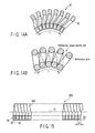
- the number of windings per the unit length L (refer to FIG. 14A) of the close-wound coil 20 becomes more than the number of windings (refer to FIG.
- the deformation amount of the wire 18 with respect to excessive curving (the load applied to one winding of the wire 18) becomes small (i.e., the coil becomes hard to break). Therefore, the resistance caused by the bending of the close-wound coil 20 with respect to a predetermined curving becomes small.
- the rotation performance of the close-wound coil 20 is increased to higher than that of the third reference close-wound coil, and the same function and effect as those of the above-mentioned embodiment can be obtained.
- FIG. 15 to FIG. 17B shows a second embodiment of the present invention.
- the parts common to those of the first embodiment are denoted by the same reference numerals, and the detailed explanation will be omitted.
- the section shape of the wire 18A of the close-wound coil 20A of this embodiment is rectangular whose dimension Y along the second axis O3 is larger than the dimension X along the third axis O4.
- the other characteristics and shapes are the same as the first embodiment.
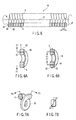
- the section shape of the wire 18A is rectangular, and advantageous effects can be obtained in the manufacturing process. Namely, when manufacturing the close-wound coil 20A of this embodiment, the wire 18A is wound around a core metal 30 so that the second axis O3 becomes orthogonal to the first axis O1 as shown in FIG. 16. In this process, the wire 18A abuts on the core metal 30 with a flat surface as shown in FIG. 17A, and the wire 18A is hard to fall down with respect to the core metal 30, enabling stable production.
- FIG. 17B shows the state that the wire 18 falls down with respect to the core metal 30 in the process of manufacturing the close-wound coil 20 of the first embodiment.
- the section shape abutting on the core metal 30 with the arc portion as the wire 18 of the first embodiment, it is considerable that the wire 18 falls down with respect to the core metal 30 in the manufacturing process.
- the section shape that the wire 18A abuts on the core metal 30 with a plane (flat portion)
- the wire 18A becomes hard to fall down with respect to the core metal 30, improving the yield of manufacturing.
- the flat portion of the section of the wire of the close-wound coil 20A of this embodiment functions more advantageously than the arc portion of the section of the wire of the close-wound coil 20 of the first embodiment.
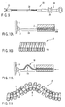
- a control wire 35 is inserted into the close-wound coils 20, 20A, as shown in FIGS. 18A and 18B.
- the control wire 35 comes into contact with the close-wound coil 20 at points by the inside uneven surface (arc portion) of the close-wound coil 20.
- control wire 35 comes into contact with the close-wound coil 20A in the inside flat surface of the close-wound coil 20A, the sliding resistance of the control wire 35 is low, and not only the movement of the control wire 35 but the movement of the end effector operated by the control wire 35 becomes light.
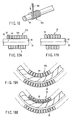
- the close-wound coils 20 and 20A are inserted into the channel 208 of an endoscope as shown in FIGS. 19A and 19B.
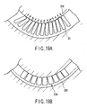
- the close-wound coil 20 of the first embodiment as shown in FIG. 19A, the close-wound coil 20 comes into contact with the inside of the endoscope channel 208 at points by the outside uneven surface (arc portion) of the close-wound coil 20.
- the endoscope channel 208 is curved with a large curvature, a load is concentrated at these portions (indicated by an arrow in the drawing), and the sliding resistance of the close-wound coil 20 is increased.
- the forward/rearward movement or rotation of the close-wound coil 20 (or the treatment section provided at the distal end of the close-wound coil 20) becomes heavy.
- the inside of the endoscope channel 208 comes into contact with the close-wound coil 20A in a face by the flat outside surface of the close-wound coil 20A as shown in FIG. 19B, and the sliding resistance of the close-wound coil 20A is low. Therefore, the forward/rearward movement or rotation of the close-wound coil 20A (or the treatment section provided at the distal end of the close-wound coil 20) becomes light.
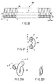
- FIG. 20 to FIG. 22B show a third embodiment of the present invention.
- the close-wound coil 20B of this embodiment is formed by a wire 18B with the elliptical section.
- the other characteristics and shapes are the same as the first embodiment. Therefore, the same functions and effects as those of the first embodiment can be obtained.
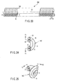
- FIG. 23 to FIG. 25 show a fourth embodiment.
- a close-wound coil 20C of this embodiment is formed by winding a set of wires 18C formed by overlapping two circular-section wires 8 in the radial direction, spirally and closely over a predetermined length around a predetermined first axis O1.
- the set of wires 18C formed by overlapping two circular-section wires 8 in the radial direction can make a section S' with a vertical-to-horizontal ratio larger than 1 similar to the section S of the wire 18 of the first embodiment. Therefore, the close-wound coil 20C formed by winding closely the set of wires 18C can also have the characteristics similar to the close-wound coil 20 of the first embodiment.
- this embodiment only two wires 8 with the circular section are used, and it is unnecessary to roll the circular-section wire 8. Thus, it is easy to manufacture a coil with a large vertical-to-horizontal ratio.
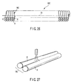
- the wires 8 may be welded.
- the two wires 8 are placed parallel and welded in their contacting parts, thereby forming a close-wound coil with a set of wires 18C combined and overlapped in the vertical direction.
- two wires 8 are made as one body, and the flexural rigidity of the set of wires 18C can be further increased.
- FIG. 28 to FIG. 30 show a fifth embodiment of the present invention.
- a close-wound coil 20D of this embodiment is formed by winding a wire 28 with a circular section (the vertical-to-horizontal ratio of the section is 1:1) spirally and closely over a predetermined length around a predetermined first axis O1.
- the wire 28 is not homogeneous in the inside, and the both side areas R1 and R1 (the areas with the crescent section) have low rigidity, and the area R2 (the area with a substantially rectangular section) near the center axis 02 held by these areas R1 and R1 has high rigidity.
- the wire 28 of this embodiment has the equivalent flexural rigidity and lower torsional rigidity, compared with a circular-section homogeneous material wire with the same dimension.
- the close-wound coil 20D of this embodiment is increased in the torsional rigidity and decreased in the flexural rigidity, compared with the close-wound coil formed by the homogeneous material wire, and the rotation transmission performance is increased.
- FIG. 31 to FIG. 33 show a sixth embodiment of the present invention.
- a close-wound coil 20E of this embodiment is formed by winding a wire 38 with a circular section (the vertical-to-horizontal ratio of the section is 1:1) spirally and closely over a predetermined length around a predetermined first axis O1.
- the wire 38 is not homogeneous in the internal structure, and the central area R3 (the area with a circular section) has high rigidity, and the peripheral area R4 (the area with a ring-like section) has low rigidity.
- the wire 38 of this embodiment has the high flexural rigidity and lower torsional rigidity, compared with a circular homogeneous material wire of the same dimension.
- the close-wound coil 20E of this embodiment is increased in the torsional rigidity and decreased in the flexural rigidity, compared with the close-wound coil formed by the homogeneous material wire, and the rotation transmission performance is increased.
- FIG. 34 to FIG. 36B show a seventh embodiment of the present invention.
- a close-wound coil 20F of this embodiment is formed by winding a wire 48 with a circular section (the vertical-to-horizontal ratio of the section is 1:1) spirally and closely over a predetermined length around a predetermined first axis O1.
- the wire 48 uses the material with anisotropic flexural rigidity. This material has high flexural rigidity in a first direction, and low flexural rigidity in a second direction vertical to the first direction.
- the first direction with high flexural rigidity is set orthogonal to the first axis O1 of the close-wound coil 20F.
- the wire 48 of this embodiment has the high flexural rigidity and lower torsional rigidity, compared with a circular homogeneous material wire of the same dimension.
- the close-wound coil 20F of this embodiment is increased in the torsional rigidity and decreased in the flexural rigidity, compared with the close-wound coil formed by the homogeneous material wire, and the rotation transmission performance is increased.
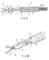
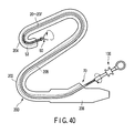
- FIG. 37 to FIG. 40 show a first example of a medical treatment tool which uses one of the above-explained close-wound coils 20 - 20F as a force transmission member.
- a medical treatment tool 70 of the first example has a clip 60 which can be left in the abdominal cavity as an end effector (treatment section).
- a distal end coil 53 with a large inside diameter is connected to the distal end side of the close-wound coil 20 - 20F.
- the distal end coil 53 has the inside diameter larger than that of the close-wound coil 20 - 20F, the vertical-to-horizontal ratio of the section of the coil wire is lower than 1, and the rotation transmission performance is lower than that of the close-wound coil 20 - 20F.
- the proximal end of the close-wound coil 20 - 20F is provided with a operation section (a rotation control section) 106 to rotate the close-wound coil 20 - 20F around the first axis O1.
- a hook 55 which can be engaged with the clip 60 is provided at the distal end of a control wire 54 inserted into the close-wound coil 20 - 20F and the distal end coil 53.
- a chip 50 is fixed to the distal end of the close-wound coil 20 - 20F, and a notch 52 is formed vertically at the end of the chip 50.
- the clip 60 is fixed to the hook 55 projected at the distal end.
- the hook 55 is pushed into the rear end of the clip 60, the rear end of the clip 60 is deformed and the hook 55 is engaged with the clip 60 (refer to FIG. 39).
- the clip 60 is provided with a retractable wing 56 (energized to the projected state), and the clip 60 can be retracted in the distal end coil 53 with the wing 56 folded (refer to FIG. 39A).
- the distal end coil 53 is set to the length capable of housing the clip 60.
- the medical treatment tool 70 is inserted into the channel 208 of the endoscope 200 with the clip 60 housed in the distal end coil 53 (the state shown in FIG. 39A), and led to a target part (e.g., a wound 80 shown in FIG. 39C) through the channel 208.
- a target part e.g., a wound 80 shown in FIG. 39C
- FIG. 40 the same reference numerals are given to the components common to those shown in FIG. 42.
- the wing 56 projects to the outside, engages with the notch 52 of the distal end coil 53, receiving the pulling force acted on the clip 60 (refer to FIG. 39B).
- the hook 55 and clip 60 can rotate relatively, but as the wing 56 of the clip 60 is engaged with the notch 52 of the chip 50, the clip 60 is rotated following the rotation of the close-wound coil 20 - 20F.
- the medical treatment tool 70 can pass smoothly through the bending section 204 of the endoscope 200. Therefore, the length of the distal end coil 53 with low rotation transmission performance can be reduced as much as possible, and deterioration of the rotation transmission performance can be suppressed to the minimum.
- FIG. 41A and FIG. 41B show a second example of a medical treatment tool which uses one of the above-explained close-wound coils 20 - 20F as a force transmission member.
- a snare 92 is fixed to the distal end of the close-wound coil 20 - 20F as an end effector.
- a flexible mantle tube 94 is provided outside of the close-wound coil 20 - 20F.
- the mantle tube 94 and close-wound coil 20 - 20F are movable relatively in the axial direction, and also rotatable relatively.
- a reference numeral 96 denotes an extension control member which prevents extension of the close-wound coil 20 - 20F.
- the snare 92 shrinks in the diameter when it is housed in the mantle tube 94, and is inserted into a body of a patient through the endoscope channel in being housed there.
- the close-wound coil 20 - 20F is pushed out in the body and the snare 92 is projected from the mantle tube 94, the snare 92 is expanded.
- the snare 92 When the close-wound coil 20 - 20F is rotated in this state through the operation section 106 provided in the proximal end side of the close-wound coil 20 - 20F, the snare 92 is rotated together with the close-wound coil 20 - 20F with respect to the mantle tube 94, and positioned to an affected part, thereby the snare 92 can be placed around a pathological change such as a polyp. Pull the close-wound coil 20 - 20F with respect to the mantle tube 94 in this state. The snare 92 ties the polyp. Flow a high frequency current in the snare 92 through the close-wound coil 20 - 20F in this state. The snare cuts off the polyp.
Landscapes
- Health & Medical Sciences (AREA)
- Surgery (AREA)
- Life Sciences & Earth Sciences (AREA)
- Engineering & Computer Science (AREA)
- Public Health (AREA)
- General Health & Medical Sciences (AREA)
- Nuclear Medicine, Radiotherapy & Molecular Imaging (AREA)
- Veterinary Medicine (AREA)
- Animal Behavior & Ethology (AREA)
- Biomedical Technology (AREA)
- Heart & Thoracic Surgery (AREA)
- Medical Informatics (AREA)
- Molecular Biology (AREA)
- General Engineering & Computer Science (AREA)
- Orthopedic Medicine & Surgery (AREA)
- Oral & Maxillofacial Surgery (AREA)
- Mechanical Engineering (AREA)
- Media Introduction/Drainage Providing Device (AREA)
- Surgical Instruments (AREA)
- Endoscopes (AREA)
Applications Claiming Priority (2)
| Application Number | Priority Date | Filing Date | Title |
|---|---|---|---|
| JP2003056215A JP4414662B2 (ja) | 2003-03-03 | 2003-03-03 | 密巻コイル及びこの密巻コイルを用いた医療用処置具 |
| JP2003056215 | 2003-03-03 |
Publications (3)
| Publication Number | Publication Date |
|---|---|
| EP1454588A2 true EP1454588A2 (fr) | 2004-09-08 |
| EP1454588A3 EP1454588A3 (fr) | 2004-10-13 |
| EP1454588B1 EP1454588B1 (fr) | 2013-05-01 |
Family
ID=32821161
Family Applications (1)
| Application Number | Title | Priority Date | Filing Date |
|---|---|---|---|
| EP04004705.2A Expired - Lifetime EP1454588B1 (fr) | 2003-03-03 | 2004-03-01 | Bobine de transmission de force pour instrument endoscopique flexible et outil de traitement médical muni d'une telle bobine |
Country Status (3)
| Country | Link |
|---|---|
| US (2) | US20040243108A1 (fr) |
| EP (1) | EP1454588B1 (fr) |
| JP (1) | JP4414662B2 (fr) |
Cited By (11)
| Publication number | Priority date | Publication date | Assignee | Title |
|---|---|---|---|---|
| EP1878402A1 (fr) * | 2006-07-13 | 2008-01-16 | Bien-Air Holding SA | Dispositif d'accouplement entre un arbre menant et un arbre mené d'une pièce à main à usage dentaire ou chirurgical |
| EP1955657A1 (fr) * | 2007-02-08 | 2008-08-13 | Olympus Medical Systems Corp. | Outil de traitement pour endoscope |
| EP1955658A1 (fr) * | 2007-02-08 | 2008-08-13 | Olympus Medical Systems Corp. | Outil de traitement endoscopique |
| CN101238971B (zh) * | 2007-02-08 | 2011-05-04 | 奥林巴斯医疗株式会社 | 内窥镜用处理器具 |
| US8303486B2 (en) | 2007-06-06 | 2012-11-06 | Olympus Medical Systems Corp. | Capsule-type endoscope system, and program and method used for the system |
| EP1820457A4 (fr) * | 2004-12-07 | 2013-06-05 | Olympus Corp | Dispositif d'introduction pour endoscope |
| US9375257B2 (en) | 2005-06-21 | 2016-06-28 | Olympus Corporation | High-frequency treatment instrument |
| US9848759B2 (en) | 2014-06-06 | 2017-12-26 | Olympus Corporation | Coil structure used in endoscope and endoscope and treatment instrument including coil structure |
| EP3187094A4 (fr) * | 2015-03-30 | 2018-07-11 | Olympus Corporation | Dispositif d'insertion |
| US10625056B2 (en) | 2013-04-01 | 2020-04-21 | Terumo Kabushiki Kaisha | Coil, guide wire, and coil manufacturing method |
| CN113081180A (zh) * | 2021-04-08 | 2021-07-09 | 张昊 | 一种可同步精细旋转刀头的十二指肠乳头切开刀 |
Families Citing this family (53)
| Publication number | Priority date | Publication date | Assignee | Title |
|---|---|---|---|---|
| EP1626665A1 (fr) * | 2003-05-16 | 2006-02-22 | Wilson-Cook Medical Inc. | Poignee d'instrument medical |
| US7641621B2 (en) * | 2003-08-25 | 2010-01-05 | Boston Scientific Scimed, Inc. | Elongated intra-lumenal medical device |
| JP4497454B2 (ja) * | 2004-04-06 | 2010-07-07 | 朝日インテック株式会社 | 医療用具 |
| US7785250B2 (en) * | 2005-08-11 | 2010-08-31 | Granit Medical Innovation, Llc | Endoscopic instrument assembly with separable operative tip and associated medical method |
| US8062306B2 (en) * | 2006-12-14 | 2011-11-22 | Ethicon Endo-Surgery, Inc. | Manually articulating devices |
| US7655004B2 (en) | 2007-02-15 | 2010-02-02 | Ethicon Endo-Surgery, Inc. | Electroporation ablation apparatus, system, and method |
| US8579897B2 (en) | 2007-11-21 | 2013-11-12 | Ethicon Endo-Surgery, Inc. | Bipolar forceps |
| US20090112059A1 (en) | 2007-10-31 | 2009-04-30 | Nobis Rudolph H | Apparatus and methods for closing a gastrotomy |
| US8771260B2 (en) | 2008-05-30 | 2014-07-08 | Ethicon Endo-Surgery, Inc. | Actuating and articulating surgical device |
| US8906035B2 (en) | 2008-06-04 | 2014-12-09 | Ethicon Endo-Surgery, Inc. | Endoscopic drop off bag |
| US8403926B2 (en) | 2008-06-05 | 2013-03-26 | Ethicon Endo-Surgery, Inc. | Manually articulating devices |
| US8347754B1 (en) * | 2008-07-02 | 2013-01-08 | Titan Medical Inc. | Multi articulating robatic instrument |
| US8888792B2 (en) | 2008-07-14 | 2014-11-18 | Ethicon Endo-Surgery, Inc. | Tissue apposition clip application devices and methods |
| JP5280767B2 (ja) * | 2008-08-14 | 2013-09-04 | 富士フイルム株式会社 | 連発式クリップ処置具 |
| US8157834B2 (en) | 2008-11-25 | 2012-04-17 | Ethicon Endo-Surgery, Inc. | Rotational coupling device for surgical instrument with flexible actuators |
| US8361066B2 (en) | 2009-01-12 | 2013-01-29 | Ethicon Endo-Surgery, Inc. | Electrical ablation devices |
| US9737334B2 (en) | 2009-03-06 | 2017-08-22 | Ethicon Llc | Methods and devices for accessing a body cavity |
| US9474540B2 (en) | 2009-10-08 | 2016-10-25 | Ethicon-Endo-Surgery, Inc. | Laparoscopic device with compound angulation |
| US20110098704A1 (en) | 2009-10-28 | 2011-04-28 | Ethicon Endo-Surgery, Inc. | Electrical ablation devices |
| US8608652B2 (en) | 2009-11-05 | 2013-12-17 | Ethicon Endo-Surgery, Inc. | Vaginal entry surgical devices, kit, system, and method |
| US8496574B2 (en) | 2009-12-17 | 2013-07-30 | Ethicon Endo-Surgery, Inc. | Selectively positionable camera for surgical guide tube assembly |
| US9028483B2 (en) | 2009-12-18 | 2015-05-12 | Ethicon Endo-Surgery, Inc. | Surgical instrument comprising an electrode |
| US8506564B2 (en) | 2009-12-18 | 2013-08-13 | Ethicon Endo-Surgery, Inc. | Surgical instrument comprising an electrode |
| US9005198B2 (en) | 2010-01-29 | 2015-04-14 | Ethicon Endo-Surgery, Inc. | Surgical instrument comprising an electrode |
| US9226760B2 (en) | 2010-05-07 | 2016-01-05 | Ethicon Endo-Surgery, Inc. | Laparoscopic devices with flexible actuation mechanisms |
| US8562592B2 (en) | 2010-05-07 | 2013-10-22 | Ethicon Endo-Surgery, Inc. | Compound angle laparoscopic methods and devices |
| US8460337B2 (en) | 2010-06-09 | 2013-06-11 | Ethicon Endo-Surgery, Inc. | Selectable handle biasing |
| US10092291B2 (en) | 2011-01-25 | 2018-10-09 | Ethicon Endo-Surgery, Inc. | Surgical instrument with selectively rigidizable features |
| US9233241B2 (en) | 2011-02-28 | 2016-01-12 | Ethicon Endo-Surgery, Inc. | Electrical ablation devices and methods |
| US9254169B2 (en) | 2011-02-28 | 2016-02-09 | Ethicon Endo-Surgery, Inc. | Electrical ablation devices and methods |
| US9314620B2 (en) | 2011-02-28 | 2016-04-19 | Ethicon Endo-Surgery, Inc. | Electrical ablation devices and methods |
| US9049987B2 (en) | 2011-03-17 | 2015-06-09 | Ethicon Endo-Surgery, Inc. | Hand held surgical device for manipulating an internal magnet assembly within a patient |
| EP2612608B1 (fr) * | 2011-09-12 | 2014-12-17 | Olympus Medical Systems Corp. | Bobine médicale, son procédé de fabrication et appareil médical |
| US9427255B2 (en) | 2012-05-14 | 2016-08-30 | Ethicon Endo-Surgery, Inc. | Apparatus for introducing a steerable camera assembly into a patient |
| US9078662B2 (en) | 2012-07-03 | 2015-07-14 | Ethicon Endo-Surgery, Inc. | Endoscopic cap electrode and method for using the same |
| US9545290B2 (en) | 2012-07-30 | 2017-01-17 | Ethicon Endo-Surgery, Inc. | Needle probe guide |
| US10314649B2 (en) | 2012-08-02 | 2019-06-11 | Ethicon Endo-Surgery, Inc. | Flexible expandable electrode and method of intraluminal delivery of pulsed power |
| US9572623B2 (en) | 2012-08-02 | 2017-02-21 | Ethicon Endo-Surgery, Inc. | Reusable electrode and disposable sheath |
| US9277957B2 (en) | 2012-08-15 | 2016-03-08 | Ethicon Endo-Surgery, Inc. | Electrosurgical devices and methods |
| US10098527B2 (en) | 2013-02-27 | 2018-10-16 | Ethidcon Endo-Surgery, Inc. | System for performing a minimally invasive surgical procedure |
| US20140277005A1 (en) * | 2013-03-14 | 2014-09-18 | Covidien Lp | Medical device including flexible elongate torque-transmitting member |
| EP3031384A4 (fr) * | 2013-08-06 | 2017-03-29 | Olympus Corporation | Dispositif d'introduction |
| JP2015128535A (ja) * | 2014-01-08 | 2015-07-16 | 国立大学法人九州大学 | 屈曲処置具用シース |
| WO2016088768A1 (fr) * | 2014-12-02 | 2016-06-09 | オリンパス株式会社 | Tube flexible et dispositif d'insertion |
| JP6084347B1 (ja) * | 2015-05-27 | 2017-02-22 | オリンパス株式会社 | 内視鏡用処置具 |
| CN212307786U (zh) * | 2017-08-08 | 2021-01-08 | 富士胶片株式会社 | 内窥镜 |
| JP7145663B2 (ja) * | 2018-07-04 | 2022-10-03 | オリンパス株式会社 | 挿入装置 |
| US11647896B2 (en) * | 2019-03-28 | 2023-05-16 | Olympus Corporation | Rollerless tubular connector for transferring rotative force from insertion section of endoscope to spiral tube |
| US12296181B2 (en) * | 2019-11-08 | 2025-05-13 | Pacesetter, Inc. | Biostimulator transport system having swaged torque shaft |
| WO2021234874A1 (fr) * | 2020-05-20 | 2021-11-25 | オリンパス株式会社 | Bobine médicale, son procédé de fabrication et équipement médical |
| US11944321B2 (en) * | 2021-01-26 | 2024-04-02 | Olympus Medical Systems Corp. | Endoscopic treatment device |
| US11937828B2 (en) * | 2021-01-26 | 2024-03-26 | Olympus Medical Systems Corp. | Endoscope treatment device |
| DE112021006770T5 (de) | 2021-03-08 | 2023-11-16 | Olympus Medical Systems Corp. | Endoskopisches Behandlungsgerät |
Citations (1)
| Publication number | Priority date | Publication date | Assignee | Title |
|---|---|---|---|---|
| US20030028206A1 (en) | 1999-02-02 | 2003-02-06 | Samuel Shiber | Vessel cleaner and barrier |
Family Cites Families (16)
| Publication number | Priority date | Publication date | Assignee | Title |
|---|---|---|---|---|
| GB191013017A (en) | 1909-05-28 | 1910-12-31 | Paul Lucas | Improvements in Inverted Incandescent Gas Lamps. |
| GB190913017A (en) * | 1909-06-03 | 1910-06-02 | Robert Thomlinson | Improvements in or relating to Flexible Shafting. |
| FR1504917A (fr) * | 1965-12-07 | 1967-12-08 | Us Catheter & Instr Corp | Guide élastique à courbure commandée pour cathéter |
| DE2903358C2 (de) | 1979-01-29 | 1983-10-27 | Kocks Technik Gmbh & Co, 4010 Hilden | Walzstraße zum Walzen von Draht oder Stäben |
| JPS56112221A (en) | 1980-02-09 | 1981-09-04 | Olympus Optical Co | Connection of each part in treating tool for endoscope |
| US5439478A (en) * | 1990-05-10 | 1995-08-08 | Symbiosis Corporation | Steerable flexible microsurgical instrument with rotatable clevis |
| US5437282A (en) * | 1993-10-29 | 1995-08-01 | Boston Scientific Corporation | Drive shaft for acoustic imaging catheters and flexible catheters |
| US5478350A (en) * | 1994-07-14 | 1995-12-26 | Symbiosis Corporation | Rack and pinion actuator handle for endoscopic instruments |
| JPH08131550A (ja) | 1994-11-11 | 1996-05-28 | Nippon Zeon Co Ltd | カテーテル |
| JP3634655B2 (ja) * | 1999-02-09 | 2005-03-30 | ペンタックス株式会社 | 内視鏡用生検鉗子 |
| US6540670B1 (en) * | 1999-03-19 | 2003-04-01 | Olympus Optical Co., Ltd. | Endoscope system |
| JP4166414B2 (ja) | 2000-05-17 | 2008-10-15 | オリンパス株式会社 | 内視鏡用処置具 |
| JP4472217B2 (ja) * | 2000-10-16 | 2010-06-02 | オリンパス株式会社 | 生体組織のクリップ装置 |
| US6716226B2 (en) * | 2001-06-25 | 2004-04-06 | Inscope Development, Llc | Surgical clip |
| JP3965022B2 (ja) | 2001-01-16 | 2007-08-22 | オリンパス株式会社 | 医療器具用のコイル、その製造方法及び製造装置 |
| JP4827304B2 (ja) | 2001-03-14 | 2011-11-30 | オリンパス株式会社 | 生体組織のクリップ装置 |
-
2003
- 2003-03-03 JP JP2003056215A patent/JP4414662B2/ja not_active Expired - Fee Related
-
2004
- 2004-03-01 EP EP04004705.2A patent/EP1454588B1/fr not_active Expired - Lifetime
- 2004-03-01 US US10/790,261 patent/US20040243108A1/en not_active Abandoned
-
2009
- 2009-04-08 US US12/420,596 patent/US8672952B2/en not_active Expired - Fee Related
Patent Citations (1)
| Publication number | Priority date | Publication date | Assignee | Title |
|---|---|---|---|---|
| US20030028206A1 (en) | 1999-02-02 | 2003-02-06 | Samuel Shiber | Vessel cleaner and barrier |
Cited By (15)
| Publication number | Priority date | Publication date | Assignee | Title |
|---|---|---|---|---|
| EP1820457A4 (fr) * | 2004-12-07 | 2013-06-05 | Olympus Corp | Dispositif d'introduction pour endoscope |
| US9375257B2 (en) | 2005-06-21 | 2016-06-28 | Olympus Corporation | High-frequency treatment instrument |
| WO2008006231A1 (fr) * | 2006-07-13 | 2008-01-17 | Bien-Air Holding Sa | Dispositif d'accouplement entre un arbre menant et un arbre mene d'une piece a main a usage dentaire ou chirurgical |
| EP1878402A1 (fr) * | 2006-07-13 | 2008-01-16 | Bien-Air Holding SA | Dispositif d'accouplement entre un arbre menant et un arbre mené d'une pièce à main à usage dentaire ou chirurgical |
| EP1955658A1 (fr) * | 2007-02-08 | 2008-08-13 | Olympus Medical Systems Corp. | Outil de traitement endoscopique |
| CN101238970B (zh) * | 2007-02-08 | 2011-09-07 | 奥林巴斯医疗株式会社 | 内窥镜用处理器具 |
| CN101238971B (zh) * | 2007-02-08 | 2011-05-04 | 奥林巴斯医疗株式会社 | 内窥镜用处理器具 |
| US9161744B2 (en) | 2007-02-08 | 2015-10-20 | Olympus Corporation | Treatment tool for endoscope |
| EP1955657A1 (fr) * | 2007-02-08 | 2008-08-13 | Olympus Medical Systems Corp. | Outil de traitement pour endoscope |
| US8303486B2 (en) | 2007-06-06 | 2012-11-06 | Olympus Medical Systems Corp. | Capsule-type endoscope system, and program and method used for the system |
| US10625056B2 (en) | 2013-04-01 | 2020-04-21 | Terumo Kabushiki Kaisha | Coil, guide wire, and coil manufacturing method |
| US9848759B2 (en) | 2014-06-06 | 2017-12-26 | Olympus Corporation | Coil structure used in endoscope and endoscope and treatment instrument including coil structure |
| EP3187094A4 (fr) * | 2015-03-30 | 2018-07-11 | Olympus Corporation | Dispositif d'insertion |
| US10105038B2 (en) | 2015-03-30 | 2018-10-23 | Olympus Corporation | Insertion apparatus |
| CN113081180A (zh) * | 2021-04-08 | 2021-07-09 | 张昊 | 一种可同步精细旋转刀头的十二指肠乳头切开刀 |
Also Published As
| Publication number | Publication date |
|---|---|
| JP2004261463A (ja) | 2004-09-24 |
| US20090198103A1 (en) | 2009-08-06 |
| JP4414662B2 (ja) | 2010-02-10 |
| EP1454588A3 (fr) | 2004-10-13 |
| US8672952B2 (en) | 2014-03-18 |
| EP1454588B1 (fr) | 2013-05-01 |
| US20040243108A1 (en) | 2004-12-02 |
Similar Documents
| Publication | Publication Date | Title |
|---|---|---|
| EP1454588A2 (fr) | Bobine de transmission de force pour instrument endoscopique flexible et outil de traitement médical muni d'une telle bobine | |
| US11596434B2 (en) | Endoscopic snare device | |
| US6485411B1 (en) | Endoscope shaft with superelastic alloy spiral frame and braid | |
| JP3684085B2 (ja) | 内視鏡用ワイヤループ型処置具 | |
| JP4160608B2 (ja) | 内視鏡用処置具 | |
| JP2025111530A (ja) | 内視鏡手術で使用する操縦可能なアーム | |
| KR101374687B1 (ko) | 의료용 스네어의 와이어 구조체 | |
| US9795401B2 (en) | Medical retrieval devices and related methods of use | |
| US6375650B1 (en) | Treating instrument for endoscope | |
| JP4360934B2 (ja) | 内視鏡の湾曲部 | |
| JP2001226888A (ja) | ミニチュアロープ | |
| JP4960424B2 (ja) | 密巻コイル及びこの密巻コイルを用いた医療用処置具 | |
| JPWO2021246292A5 (fr) | ||
| JP4521603B2 (ja) | 内視鏡用処置具 | |
| WO2012090859A1 (fr) | Instrument de traitement pour endoscopes | |
| JPH1176251A (ja) | 内視鏡用スネア | |
| JP2002253559A (ja) | 内視鏡用ワイヤループ型処置具 | |
| JP4448362B2 (ja) | 内視鏡の湾曲装置 | |
| JP2006230635A (ja) | 医療用処置具 | |
| JP2021171316A (ja) | 内視鏡用スネア | |
| JP3880472B2 (ja) | 医療器具用ワイヤー | |
| JP2021175496A (ja) | 内視鏡用スネア | |
| JP3231667B2 (ja) | 内視鏡用ワイヤループ型処置具 | |
| JP4390510B2 (ja) | 内視鏡用高周波スネア | |
| JP2016123805A (ja) | 内視鏡用処置具 |
Legal Events
| Date | Code | Title | Description |
|---|---|---|---|
| PUAI | Public reference made under article 153(3) epc to a published international application that has entered the european phase |
Free format text: ORIGINAL CODE: 0009012 |
|
| PUAL | Search report despatched |
Free format text: ORIGINAL CODE: 0009013 |
|
| 17P | Request for examination filed |
Effective date: 20040301 |
|
| AK | Designated contracting states |
Kind code of ref document: A2 Designated state(s): AT BE BG CH CY CZ DE DK EE ES FI FR GB GR HU IE IT LI LU MC NL PL PT RO SE SI SK TR |
|
| AX | Request for extension of the european patent |
Extension state: AL LT LV MK |
|
| AK | Designated contracting states |
Kind code of ref document: A3 Designated state(s): AT BE BG CH CY CZ DE DK EE ES FI FR GB GR HU IE IT LI LU MC NL PL PT RO SE SI SK TR |
|
| AX | Request for extension of the european patent |
Extension state: AL LT LV MK |
|
| RIC1 | Information provided on ipc code assigned before grant |
Ipc: 7A 61B 17/32 B Ipc: 7A 61B 17/10 B Ipc: 7A 61B 17/00 A Ipc: 7F 16C 1/04 B |
|
| AKX | Designation fees paid |
Designated state(s): DE FR IE |
|
| 17Q | First examination report despatched |
Effective date: 20101112 |
|
| RIC1 | Information provided on ipc code assigned before grant |
Ipc: A61B 17/00 20060101AFI20121017BHEP Ipc: F16C 1/02 20060101ALI20121017BHEP Ipc: A61B 17/10 20060101ALI20121017BHEP Ipc: A61B 17/32 20060101ALI20121017BHEP |
|
| GRAP | Despatch of communication of intention to grant a patent |
Free format text: ORIGINAL CODE: EPIDOSNIGR1 |
|
| GRAS | Grant fee paid |
Free format text: ORIGINAL CODE: EPIDOSNIGR3 |
|
| GRAA | (expected) grant |
Free format text: ORIGINAL CODE: 0009210 |
|
| AK | Designated contracting states |
Kind code of ref document: B1 Designated state(s): DE FR IE |
|
| REG | Reference to a national code |
Ref country code: IE Ref legal event code: FG4D |
|
| REG | Reference to a national code |
Ref country code: DE Ref legal event code: R096 Ref document number: 602004041937 Country of ref document: DE Effective date: 20130627 |
|
| PLBE | No opposition filed within time limit |
Free format text: ORIGINAL CODE: 0009261 |
|
| STAA | Information on the status of an ep patent application or granted ep patent |
Free format text: STATUS: NO OPPOSITION FILED WITHIN TIME LIMIT |
|
| 26N | No opposition filed |
Effective date: 20140204 |
|
| REG | Reference to a national code |
Ref country code: DE Ref legal event code: R097 Ref document number: 602004041937 Country of ref document: DE Effective date: 20140204 |
|
| REG | Reference to a national code |
Ref country code: FR Ref legal event code: ST Effective date: 20141128 |
|
| REG | Reference to a national code |
Ref country code: IE Ref legal event code: MM4A |
|
| PG25 | Lapsed in a contracting state [announced via postgrant information from national office to epo] |
Ref country code: FR Free format text: LAPSE BECAUSE OF NON-PAYMENT OF DUE FEES Effective date: 20140331 Ref country code: IE Free format text: LAPSE BECAUSE OF NON-PAYMENT OF DUE FEES Effective date: 20140301 |
|
| PGFP | Annual fee paid to national office [announced via postgrant information from national office to epo] |
Ref country code: DE Payment date: 20190321 Year of fee payment: 16 |
|
| REG | Reference to a national code |
Ref country code: DE Ref legal event code: R119 Ref document number: 602004041937 Country of ref document: DE |
|
| PG25 | Lapsed in a contracting state [announced via postgrant information from national office to epo] |
Ref country code: DE Free format text: LAPSE BECAUSE OF NON-PAYMENT OF DUE FEES Effective date: 20201001 |