EP1454676A2 - Appareil pour délivrer un adhésif - Google Patents
Appareil pour délivrer un adhésif Download PDFInfo
- Publication number
- EP1454676A2 EP1454676A2 EP04013577A EP04013577A EP1454676A2 EP 1454676 A2 EP1454676 A2 EP 1454676A2 EP 04013577 A EP04013577 A EP 04013577A EP 04013577 A EP04013577 A EP 04013577A EP 1454676 A2 EP1454676 A2 EP 1454676A2
- Authority
- EP
- European Patent Office
- Prior art keywords
- bore
- plunger
- pole
- adhesive
- valve seat
- Prior art date
- Legal status (The legal status is an assumption and is not a legal conclusion. Google has not performed a legal analysis and makes no representation as to the accuracy of the status listed.)
- Withdrawn
Links
Images

Classifications
-
- B—PERFORMING OPERATIONS; TRANSPORTING
- B05—SPRAYING OR ATOMISING IN GENERAL; APPLYING FLUENT MATERIALS TO SURFACES, IN GENERAL
- B05C—APPARATUS FOR APPLYING FLUENT MATERIALS TO SURFACES, IN GENERAL
- B05C5/00—Apparatus in which liquid or other fluent material is projected, poured or allowed to flow on to the surface of the work
- B05C5/02—Apparatus in which liquid or other fluent material is projected, poured or allowed to flow on to the surface of the work the liquid or other fluent material being discharged through an outlet orifice by pressure, e.g. from an outlet device in contact or almost in contact, with the work
-
- B—PERFORMING OPERATIONS; TRANSPORTING
- B05—SPRAYING OR ATOMISING IN GENERAL; APPLYING FLUENT MATERIALS TO SURFACES, IN GENERAL
- B05C—APPARATUS FOR APPLYING FLUENT MATERIALS TO SURFACES, IN GENERAL
- B05C5/00—Apparatus in which liquid or other fluent material is projected, poured or allowed to flow on to the surface of the work
- B05C5/02—Apparatus in which liquid or other fluent material is projected, poured or allowed to flow on to the surface of the work the liquid or other fluent material being discharged through an outlet orifice by pressure, e.g. from an outlet device in contact or almost in contact, with the work
- B05C5/0225—Apparatus in which liquid or other fluent material is projected, poured or allowed to flow on to the surface of the work the liquid or other fluent material being discharged through an outlet orifice by pressure, e.g. from an outlet device in contact or almost in contact, with the work characterised by flow controlling means, e.g. valves, located proximate the outlet
-
- B—PERFORMING OPERATIONS; TRANSPORTING
- B05—SPRAYING OR ATOMISING IN GENERAL; APPLYING FLUENT MATERIALS TO SURFACES, IN GENERAL
- B05C—APPARATUS FOR APPLYING FLUENT MATERIALS TO SURFACES, IN GENERAL
- B05C5/00—Apparatus in which liquid or other fluent material is projected, poured or allowed to flow on to the surface of the work
- B05C5/02—Apparatus in which liquid or other fluent material is projected, poured or allowed to flow on to the surface of the work the liquid or other fluent material being discharged through an outlet orifice by pressure, e.g. from an outlet device in contact or almost in contact, with the work
- B05C5/027—Coating heads with several outlets, e.g. aligned transversally to the moving direction of a web to be coated
- B05C5/0275—Coating heads with several outlets, e.g. aligned transversally to the moving direction of a web to be coated flow controlled, e.g. by a valve
- B05C5/0279—Coating heads with several outlets, e.g. aligned transversally to the moving direction of a web to be coated flow controlled, e.g. by a valve independently, e.g. individually, flow controlled
Definitions
- This invention is directed to a fluid dispenser, such as for the dispensing fluids, such as adhesives, sealants, water and caulks. More particularly, this invention is also directed to an electromagnetically actuated fluid dispenser for dispensing heated fluid materials such as, for example, hot melt adhesives.
- Electromagnetic dispensers have been developed wherein the plunger is driven open by an electromagnetic field and closed by a spring biasing means.
- Electromagnetic dispensers otherwise known as (electric guns) are generally larger than standard pneumatic dispenser. This increase in size does not lend electric guns or dispensers to be readily useable in multiple configurations, such as mounting a plurality of dispensers side by side to form a bank of dispensers. In many applications, such as carton sealing, it is desirous to apply a plurality of parallel beads to a substrate on fairly close centers. However, due to the larger size of electromagnetic guns it is difficult to apply closely spaced beads of material to substrates.
- a compact electromagnetic dispenser which is capable of operating at fast cycle rates, and is also capable of operating in a bank of dispenser so that closely spaced apart beads of material may be dispensed onto a substrate.
- centerline spacing from one gun module to the next is therefore important. If the gun modules are mounted side by side, it may be very desirous to have the centerline spacing as small as possible in order to produce beads having small centerlines. As such, it is desirable that the width of the gun modules be as small as possible.
- an apparatus for dispensing an adhesive material comprising: a body defining a fluid chamber, the fluid chamber extending from a first end to an outlet at a second end; a fixed pole disposed at the first end of the fluid chamber and extending away therefrom, wherein a portion of said fixed pole is in fluid contact with the fluid material within the fluid chamber; an inlet for coupling the fluid chamber to a source of adhesive material; a coil for generating an electromagnetic field, disposed about a portion of the pole and a portion of the fluid chamber; a plunger disposed within the fluid chamber adjacent to the fixed pole and mounted for reciprocal movement therein between closed and retracted positions when subjected to said electromagnetic field, such that when said plunger is in said closed position the outlet is blocked to prevent fluid flow therefrom and in said retracted position fluid flow is emitted from the outlet; and a rectangular housing having a bore therein and a pair of end caps, one cap disposed in each end of said housing and each cap having
- an apparatus for dispensing an adhesive comprising: a housing defining a bore therein, said bore having a first and a second end; an inlet for coupling the bore to a source of adhesive; a pole, extending form the first end of the bore such that a portion of an external surface of the pole is in fluid communication with the adhesive; a coil for generating an electromagnetic field, disposed about a portion of the pole and the bore; a discharge opening coupled to the second end of the bore; a plunger, having first and second ends, disposed within the bore and mounted for reciprocal movement between a closed position and an open position, wherein in said open position, adhesive is dispensed from the discharge opening and in said closed position, adhesive is prevented from being dispensed from the discharge opening; a pair of magnetic end caps disposed within the housing, one located at either end of the coil; a flux guide member, coupled between the end caps having a non-uniform radial cross-section for guiding lines of flux
- an apparatus for dispensing adhesive comprising: a valve seat body, said body having a stepped bore therein, one end of said bore coupled to a discharge outlet, and an inlet coupled to the stepped bore and adapted to receive a source of adhesive, said valve seat body being non-magnetic; a non-magnetic sleeve member, having a bore therein, one end of the sleeve member engaging the stepped bore of the valve seat body; a pole, attached to a distal end of the sleeve member from the valve seat body and extending from the sleeve member; a coil assembly, for generating an electromagnetic field, disposed about a portion of both the pole and the sleeve member; first and second end caps, each end cap having a bore therein, the first end cap disposed between the coil and the valve seat body and the second end cap disposed about a portion of the pole, a non-circular housing,
- a method of dispensing an adhesive material comprising the steps of: directing a flow of said material through a bore containing a plunger slidably mounted and contained therein; directing the flow of said material about a portion of an electromagnetic pole extending from said bore; generating an electromagnetic field; causing the electromagnetic field to pass axially through the pole and said plunger; and further directing the field in concentrated axial areas, parallel to that passing through said pole and plunger; wherein the electromagnetic field effectuates movement of the plunger from a closed to an open position such that the adhesive material is directed past the plunger and discharged from a discharge orifice.
- a method of dispensing an adhesive material comprising the steps of: mounting a plurality of gun modules to a manifold in side-by-side relationship; directing a flow of said adhesive material through a bore of each gun module containing a plunger slidably mounted therein, and further directing the flow of said polymeric material about a portion of a electromagnetic pole; generating an electromagnetic field in one or.
- the gun modules and causing the electromagnetic field for such gun module or modules, to pass axially through the pole and said plunger of the respective gun module, and further directing the field to concentrate the majority of the field in a first face of the module adjacent to the manifold and a second face diametrically opposed to the first face; wherein the electromagnetic field of each module effectuates movement of the plunger of the module from a closed to an open position such that the adhesive material is directed past the plunger and discharged from a discharge orifice.
- Axial and “Axially” are used herein to refer to lines or directions that are generally parallel to the axis of reciprocal motion of the plunger of the dispenser.
- Ring and “Radially” are used to mean directions radially toward or away from the axis of motion of the plunger.
- Hot melt materials are those materials which are normally solid at room or ambient temperature but, when heated, are converted to a liquid state. It should be understood that the methods and apparatus of this invention are believed to be equally applicable for use in connection with the dispensing of other heated fluid materials, such as waxes, as well as those adhesives which are normally a liquid at room or ambient temperature and therefore do not require heating and are sometimes referred to as cold glue.
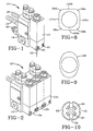
- the dispenser 10 includes a dispenser body, otherwise known as a gun module or valve 12, according to one embodiment of this invention, mounted to a service block 14, otherwise known as a manifold.
- the service block 14 has an inlet 16, capable of being coupled to an adhesive supply source (not shown) as well as internal fluid passages and an outlet for supplying the adhesive to the module 12 and further contains heaters and temperature sensors, coupled to control circuitry via conduits 18, to maintain the temperature of the hot melt adhesive within the dispenser 10.
- the dispenser module 12 may be mounted to the service block 14 by mounting screws 20. The module 12 receives the adhesive from the service block and in turn dispenses or applies the adhesive 22 to a substrate.
- FIG. 1 While the dispenser or gun 10 of FIG. 1 utilizes only one gun module 12, a gun may utilize multiple gun modules.
- a gun shown generally by reference numeral 10'.
- the gun 10' includes three gun modules 12A, 12B, and 12C, each identical to gun module 12 of FIG. 1, mounted to a manifold 14' in side-by-side relationship for dispensing 3 streams or beads of adhesive onto a substrate.
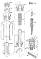
- Gun module 12 includes an inlet port 24 for receiving the liquid material from the manifold or service block 14, 14'.
- An O-ring 26 is mounted within a groove about the inlet port 24, for sealing and preventing the leakage of material therefrom.
- the inlet port communicates with a passage 28 to a fluid chamber 30.
- the fluid chamber 30 is coupled to discharge outlet 32 for dispensing the adhesive material therefrom.
- Inlet 24, passageway 28, and outlet 32 are all disposed in valve seat body 34.
- Valve seat body 34 includes a threaded step bore 36.
- valve seat body 34 adjacent to the discharge outlet 32 may include threads 38 for mating with and attaching a nozzle (not shown).
- valve seat body 34 is comprised of brass for those applications employing a heated material, such as hot melt or other thermoplastic materials. This is to provide good heat transfer from the heated manifold 14, 14' in order to maintain the desired temperature of the fluid contained within the gun body 12 prior to dispensing through discharge outlet 32.
- a heated material such as hot melt or other thermoplastic materials. This is to provide good heat transfer from the heated manifold 14, 14' in order to maintain the desired temperature of the fluid contained within the gun body 12 prior to dispensing through discharge outlet 32.
- the valve seat body may be manufactured from some other non-magnetic material that is more corrosion resistant.
- Sleeve member 40 mounted within valve seat body 34 is a sleeve member 40.
- Sleeve member 40 includes a bore 41 therein and further including an end 40a which threadably engages the threads 38 of stepped bore 36 of the valve seat body 34. End 40a further includes a groove for receiving an O-ring 42.
- Sleeve member 40 should be a non-magnetic material and may be manufactured from a type 303 stainless steel.
- Sleeve member 40 at its distal end from the valve seat body 34 receives a pole piece 44. Pole piece 44 is manufactured from a ferromagnetic material or other soft magnetic material.
- pole piece 44 is attached to the sleeve member 40. This may be accomplished by knurling a portion 46 of the pole 44 retained by or within the sleeve member 40 as a pressed fit. The attachment of the pole piece to the sleeve is further accomplished by brazing, such as by forming a brazed ring 48.
- pole piece 44 is of a magnetic material, such as a heat treated magnetic stainless steel, such as 430 FR stainless steel. For certain less corrosive fluids, it is preferred to use a stainless steel having a low chrome content, such as those wherein the chrome content is about 12%.
- An electromagnetic coil assembly 56 is located around the sleeve 40 and is enclosed by housing 58.
- the coil assembly should not be attached to the sleeve member, as the sleeve/pole piece needs to be able to be rotated as will be discussed further.
- the electromagnetic coil assembly generates an electromagnetic field when it is subjected to a source of electrical power (not shown).
- the electromagnetic coil assembly 56 includes a coil 60 comprising a plurality of windings wrapped around a bobbin or spool 62.
- the windings of the coil 60 may be encased in a potting layer of epoxy.
- the spool 62 is located about the sleeve 40 such that a portion of the pole piece 44 is located within the bore area of the spool.
- end caps 64 Located at either end of housing 58 are end caps 64. Each end cap 64 is press fitted flush into the housing 58.
- the end caps and the housing are comprised of a magnetic material, such as magnetic iron, such as a silicone iron alloy, with a 21 ⁇ 2% silicone content or some other ferromagnetic material or soft magnetic material.
- the housing is manufactured from the same materials as the end caps.
- the spool 62 may include an axially extending portion 66 to provide a spacing between the spool from the end caps 64.
- the resulting space between the spool and the end caps is filled with a highly thermally conductive adhesive for bonding the spool assembly with the end caps and the housing 58.
- Electrical leads 68 pass through an aperture 70 in the housing 58 coupled to a source of electrical power, such as carried by the service manifold 14.
- the distal end 72 of pole piece 44 includes the plurality of threads 74 about its periphery, as well as a slot 76.
- the threads 74 engage a lock washer 78 and a retaining nut 80 for retaining the housing 58 in engagement with the pole 44 and the valve seat body 34.
- Pole piece 44, sleeve 40, and valve seat body 34 together form the fluid chamber 30.
- a plunger or armature 50 which is slidably mounted for reciprocal motion.
- the plunger is also manufactured of a ferromagnetic material or other soft magnetic material.
- the plunger 50 has a valve needle 52, such as a ball, located at one end of the plunger 50 for mating with a seat 54, located within the valve seat body 34, in the closed position.
- Seat 54 may be a carbide seat brazed into valve seat body 34.
- the plunger 50 is stepped having a first portion 82 having a diameter which closely approximates that of the diameter of the bore 41 of the sleeve member.
- bypass channels 83 extending axially along the outer periphery. Causing the fluid to flow past the plunger in this manner helps to prevent dead spots from occurring in the flow of the adhesive through the dispenser, as well as helping to reduce the force required to move the plunger back and forth. With dead spots, the fluid may begin to oxidize to produce undesirable particles or chunks, commonly know as char.
- the bypass channels have a semi-circular cross-section. Having a semi-circular cross-section provides for better magnetic efficiency and improved fluid flow over a straight sided slot.
- the first portion 82 of the plunger 50 further includes a stepped bore 84 having a spring 86 retained therein for engaging the plunger 50 and the pole piece 44.
- the spring 86 provides a biasing force for urging the ball 52 into engagement with the seat 54 to prevent the flow of material from the discharge outlet 32.
- the face 88 of the first portion 82 of the plunger 50 When dispensing, the face 88 of the first portion 82 of the plunger 50 will be adjacent to and/or in contact with the end 90 of the fixed pole 44. Fluid material trapped between face 88 of the plunger 50 and the end 90 of the pole 44 will contribute to an increase in the force required to begin to move the plunger to the closed position and/or will cause the closing response time to increase. This phenomenon is similar to the increase in force that is required to separate two pieces of glass which have a drop of fluid placed in between them. As used herein, this phenomenon will be referred to as squeeze film lubrication.
- fluid is directed into the openings of fluid channel 92, into stepped bore 84, and eventually into the area formed between the fixed pole 44 and the face 88 of the plunger 50.
- the introduction of fluid into this area from bore 84 reduces the vacuum like attraction force between the pole and the plunger as the plunger is being driven to the closed position.
- the face 88 may be provided with a radial channel 85 intersecting with the through bore 84.
- radial channel 85 has a semi-circular cross-section.
- the flow path 84, 92 helps in decreasing the response time necessary to move the plunger to the open position.
- the plunger moves from the closed to the open position, there is fluid between the face 88 of the plunger and the pole piece 44 which must be displaced.
- the head acting much like a piston will displace fluid through the bypass channels 83, as well as through flow channels 84 and 92, and into the fluid chamber 30.
- the generated magnetic field will induce an electromagnetic field which will cause the plunger or armature 50 to be attracted to pole piece 44. This force will be sufficient to overcome the force of the spring 86 thereby drawing the face 88 of the plunger 44 towards the end 90 of pole 44. This in turn causes the ball 52 to be spaced from the seat 54 thereby causing a fluid flow path from the fluid chamber 30 to the discharge outlet 32. This allows the adhesive to be dispensed from the outlet 32.
- the coil is de-energized, the field collapses and the plunger 50 will be moved back to the closed position by the spring 86.
- the electromagnetic field generated however, is not symmetrical throughout the axial length of the gun module.
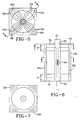
- the magnetic circuitry of the gun module is represented schematically.
- the electromagnetic field or lines of flux shown generally by reference EM passes through pole piece 44, plunger 50, the end caps 64, and the corners 58a, b, c, d of the housing 58a.
- lines of flux are bent or concentrated into the comer regions of the housing. It is preferable that little or no flux passes through the regions between the corners of the housing 58.
- the lines of flux are not distributed uniformly about the housing 58, but rather, are distributed un-uniformly and concentrated in discrete areas.
- the housing 58 provides a member for guiding the lines of flux of the electromagnetic field between the end caps.
- the lines of flux in the comers of the housing or guide member 58 will pass axially from one end of the housing to the other and will be parallel to those passing through the pole and plunger.
- the outer core or housing is cylindrical.
- the same cross-sectional area but re-configurating it into a rectangle or other geometric shape, such as for example a trapezoid allows for a smaller centerline spacing between the modules. This allows for a smaller spacing between streams of material to be applied to the substrate.
- the housing is illustrated as having a rectangular cross-section, it is foreseeable to utilize shapes that are substantially rectangular and still obtain the benefit of reduced spacing.
- corner regions 58a-d of the housing could be rounded while still having substantially flat sides 100a-d, therebetween.
- the flat sides could each be somewhat curved.
- the outer periphery 102 of the housing may have a configuration that is substantially that of an ellipse or substantially oblong.
- the thickness X of an end cap 64 is a function of the internal surface area of the bore 94 of the end cap.
- the internal surface area of the bore 94 of an end cap should be equal to the cross-sectional area of the housing 58.
- the fitting of the gap G between the pole 46 and the armature 50 is preferably in the .010" ⁇ .001.
- the stroke of the plunger 50 can be adjusted by inserting a screw driver into the slot 76 of pole piece 46.
- Rotating pole piece 46 causes sleeve member 40 to be adjusted by rotating on the threads of the valve seat body 34.
- the housing 58, including the coil assembly 56 is then placed over the sleeve.
- the body 58 has a locating pin which matches up with a corresponding hole the valve seat body 34. Once in place, the lock washer and nut are then tightened.
- a nozzle gauge is then attached to the valve seat body by screwing it onto the threads 38. With the sleeve/pole bottomed out, the plunger 58 should not move. Using the screw driver in slot 76 of the pole piece, the pole piece may be rotated until the gauge indicates that the proper gap setting has been obtained. At which point in time the nut 80 may be tightened completely and the gap, i.e. the movement of the ball from the seat as recorded by the gauge provides a spring force against the ball, can be verified.
Landscapes
- Coating Apparatus (AREA)
- Magnetically Actuated Valves (AREA)
- Nozzles (AREA)
- Application Of Or Painting With Fluid Materials (AREA)
Applications Claiming Priority (3)
| Application Number | Priority Date | Filing Date | Title |
|---|---|---|---|
| US08/948,728 US5875922A (en) | 1997-10-10 | 1997-10-10 | Apparatus for dispensing an adhesive |
| EP98117619A EP0908240B1 (fr) | 1997-10-10 | 1998-09-17 | Appareil pour délivrer un adhésif |
| US948728 | 2001-09-07 |
Related Parent Applications (2)
| Application Number | Title | Priority Date | Filing Date |
|---|---|---|---|
| EP98117619.1 Division | 1998-09-17 | ||
| EP98117619A Division EP0908240B1 (fr) | 1997-10-10 | 1998-09-17 | Appareil pour délivrer un adhésif |
Publications (2)
| Publication Number | Publication Date |
|---|---|
| EP1454676A2 true EP1454676A2 (fr) | 2004-09-08 |
| EP1454676A3 EP1454676A3 (fr) | 2010-11-17 |
Family
ID=25488197
Family Applications (2)
| Application Number | Title | Priority Date | Filing Date |
|---|---|---|---|
| EP04013577A Withdrawn EP1454676A3 (fr) | 1997-10-10 | 1998-09-17 | Appareil pour délivrer un adhésif |
| EP98117619A Expired - Lifetime EP0908240B1 (fr) | 1997-10-10 | 1998-09-17 | Appareil pour délivrer un adhésif |
Family Applications After (1)
| Application Number | Title | Priority Date | Filing Date |
|---|---|---|---|
| EP98117619A Expired - Lifetime EP0908240B1 (fr) | 1997-10-10 | 1998-09-17 | Appareil pour délivrer un adhésif |
Country Status (9)
| Country | Link |
|---|---|
| US (1) | US5875922A (fr) |
| EP (2) | EP1454676A3 (fr) |
| JP (1) | JP4372865B2 (fr) |
| KR (1) | KR100499738B1 (fr) |
| AU (1) | AU741767B2 (fr) |
| CA (1) | CA2247628A1 (fr) |
| DE (3) | DE29824854U1 (fr) |
| ES (1) | ES2226047T3 (fr) |
| TW (1) | TW390823B (fr) |
Cited By (1)
| Publication number | Priority date | Publication date | Assignee | Title |
|---|---|---|---|---|
| TWI884515B (zh) * | 2022-09-07 | 2025-05-21 | 大陸商常州銘賽機器人科技股份有限公司 | 螺桿閥及其出膠控制方法 |
Families Citing this family (219)
| Publication number | Priority date | Publication date | Assignee | Title |
|---|---|---|---|---|
| US6220843B1 (en) * | 1998-03-13 | 2001-04-24 | Nordson Corporation | Segmented die for applying hot melt adhesives or other polymer melts |
| US6422428B1 (en) | 1998-04-20 | 2002-07-23 | Nordson Corporation | Segmented applicator for hot melt adhesives or other thermoplastic materials |
| US6032832A (en) * | 1998-05-11 | 2000-03-07 | Golden Gate Microsystems, Inc. | Glue head |
| US6076711A (en) * | 1999-03-18 | 2000-06-20 | Illinois Tool Works Inc. | High flow pneumatic adhesive applicator valve |
| KR100321195B1 (ko) * | 1999-10-21 | 2002-01-19 | 안영후 | 스프레이 장치 |
| US6253972B1 (en) | 2000-01-14 | 2001-07-03 | Golden Gate Microsystems, Inc. | Liquid dispensing valve |
| US6305583B1 (en) | 2000-02-11 | 2001-10-23 | Tlx Technologies | Valve for viscous fluid applicator |
| US6413315B1 (en) | 2000-03-02 | 2002-07-02 | Riverwood International Corporation | Automated adjustable gluing apparatus for a packaging machine |
| US6401976B1 (en) | 2000-03-23 | 2002-06-11 | Nordson Corporation | Electrically operated viscous fluid dispensing apparatus and method |
| US6257445B1 (en) * | 2000-03-23 | 2001-07-10 | Nordson Corporation | Electrically operated viscous fluid dispensing apparatus and method |
| US7289878B1 (en) * | 2000-05-15 | 2007-10-30 | Nordson Corporation | Apparatus and method for modifying operation of an electric gun driver |
| US6761290B2 (en) * | 2000-05-16 | 2004-07-13 | Nordson Corporation | Device for applying fluid material on a substrate, and application valve |
| DE10023673B4 (de) * | 2000-05-16 | 2007-11-22 | Nordson Corp., Westlake | Verteilervorrichtung zum Verteilen von Fluiden sowie Vorrichtung zum Abgeben und Auftragen von Fluid, insbesondere Klebstoff |
| JP2002130511A (ja) * | 2000-10-26 | 2002-05-09 | Aisin Seiki Co Ltd | 電磁弁 |
| DE20104677U1 (de) * | 2001-03-17 | 2001-05-31 | DBT Deutsche Bergbau-Technik GmbH, 44534 Lünen | Elektromagnet-Schaltvorrichtung |
| AU777531B2 (en) * | 2001-03-17 | 2004-10-21 | Caterpillar Global Mining Europe Gmbh | An electromagnet switching device |
| TW483792B (en) * | 2001-03-21 | 2002-04-21 | Hannstar Display Corp | Stroke and pressure adjusting device for welding operation in soldering machine |
| JP3947957B2 (ja) * | 2001-08-10 | 2007-07-25 | Smc株式会社 | 電磁弁 |
| US7230670B2 (en) * | 2001-10-05 | 2007-06-12 | Lg.Philips Lcd Co., Ltd. | Method for fabricating LCD |
| US7253866B2 (en) * | 2001-10-27 | 2007-08-07 | Lg.Philips Lcd Co., Ltd. | Method of fabricating liquid crystal display device |
| US6819391B2 (en) | 2001-11-30 | 2004-11-16 | Lg. Philips Lcd Co., Ltd. | Liquid crystal display panel having dummy column spacer with opened portion |
| KR100685948B1 (ko) * | 2001-12-14 | 2007-02-23 | 엘지.필립스 엘시디 주식회사 | 액정표시소자 및 그 제조방법 |
| US7292304B2 (en) * | 2001-12-17 | 2007-11-06 | Lg.Philips Lcd Co., Ltd. | Liquid crystal display panel and method for fabricating the same comprising a dummy column spacer to regulate a liquid crystal flow and a supplemental dummy column spacer formed substantially parallel and along the dummy column spacer |
| KR100652045B1 (ko) * | 2001-12-21 | 2006-11-30 | 엘지.필립스 엘시디 주식회사 | 액정표시소자 및 그 제조방법 |
| KR100685949B1 (ko) | 2001-12-22 | 2007-02-23 | 엘지.필립스 엘시디 주식회사 | 액정표시소자 및 그 제조방법 |
| KR100652046B1 (ko) * | 2001-12-22 | 2006-11-30 | 엘지.필립스 엘시디 주식회사 | 액정표시소자 및 그 제조방법 |
| US7617951B2 (en) | 2002-01-28 | 2009-11-17 | Nordson Corporation | Compact heated air manifolds for adhesive application |
| US7362407B2 (en) * | 2002-02-01 | 2008-04-22 | Lg.Philips Lcd Co., Ltd. | Method of fabricating liquid crystal display device |
| KR100510718B1 (ko) * | 2002-02-04 | 2005-08-30 | 엘지.필립스 엘시디 주식회사 | 액정표시소자의 제조 장치 |
| JP2003233080A (ja) * | 2002-02-05 | 2003-08-22 | Lg Phillips Lcd Co Ltd | 合着装置及びこれを用いた液晶表示装置の製造方法 |
| KR100510719B1 (ko) * | 2002-02-05 | 2005-08-30 | 엘지.필립스 엘시디 주식회사 | 액정 표시 장치의 제조 방법 |
| KR100469353B1 (ko) * | 2002-02-06 | 2005-02-02 | 엘지.필립스 엘시디 주식회사 | 액정표시소자용 합착 장치 |
| KR100469354B1 (ko) * | 2002-02-06 | 2005-02-02 | 엘지.필립스 엘시디 주식회사 | 액정 표시 장치의 제조 방법 |
| KR100817129B1 (ko) | 2002-02-07 | 2008-03-27 | 엘지.필립스 엘시디 주식회사 | 액정 패널의 절단 장치 및 그 방법 |
| KR100672640B1 (ko) * | 2002-02-07 | 2007-01-23 | 엘지.필립스 엘시디 주식회사 | Uv조사장치 및 그를 이용한 액정표시소자의 제조방법 |
| US7410109B2 (en) | 2002-02-07 | 2008-08-12 | Lg Display Co., Ltd. | Liquid crystal dispensing apparatus with nozzle protecting device |
| KR100789454B1 (ko) * | 2002-02-09 | 2007-12-31 | 엘지.필립스 엘시디 주식회사 | 액정 패널의 절단 장치 및 그 방법 |
| KR100832292B1 (ko) * | 2002-02-19 | 2008-05-26 | 엘지디스플레이 주식회사 | 액정 패널의 절단 장치 |
| CN100385300C (zh) * | 2002-02-20 | 2008-04-30 | Lg.菲利浦Lcd株式会社 | 液晶显示器的制造方法 |
| KR100789455B1 (ko) | 2002-02-20 | 2007-12-31 | 엘지.필립스 엘시디 주식회사 | 액정 패널의 절단 방법 |
| KR100505180B1 (ko) * | 2002-02-20 | 2005-08-01 | 엘지.필립스 엘시디 주식회사 | 노즐세정장치를 구비한 액정적하장치 및 액정적하방법 |
| US6824023B2 (en) * | 2002-02-20 | 2004-11-30 | Lg. Philips Lcd Co., Ltd. | Liquid crystal dispensing apparatus |
| KR100469359B1 (ko) * | 2002-02-20 | 2005-02-02 | 엘지.필립스 엘시디 주식회사 | 액정표시소자용 합착 장치 |
| KR100672641B1 (ko) * | 2002-02-20 | 2007-01-23 | 엘지.필립스 엘시디 주식회사 | 액정표시소자 및 그 제조방법 |
| KR100532083B1 (ko) * | 2002-02-20 | 2005-11-30 | 엘지.필립스 엘시디 주식회사 | 일체화된 니들시트를 가진 액정적하장치 |
| US7006202B2 (en) * | 2002-02-21 | 2006-02-28 | Lg.Philips Lcd Co., Ltd. | Mask holder for irradiating UV-rays |
| US6864948B2 (en) * | 2002-02-22 | 2005-03-08 | Lg.Philips Lcd Co., Ltd. | Apparatus for measuring dispensing amount of liquid crystal drops and method for manufacturing liquid crystal display device using the same |
| KR100469508B1 (ko) | 2002-02-22 | 2005-02-02 | 엘지.필립스 엘시디 주식회사 | 스프링의 장력조정에 의해 액정적하량을 제어가 가능한액정적하장치 |
| KR100741897B1 (ko) * | 2002-03-22 | 2007-07-24 | 엘지.필립스 엘시디 주식회사 | 가스 온도 조절 기능을 갖는 합착 장치 |
| KR100469360B1 (ko) * | 2002-02-22 | 2005-02-02 | 엘지.필립스 엘시디 주식회사 | 액정표시소자의 제조 장비용 진공 합착 장치 및 구동 방법 |
| US6803984B2 (en) | 2002-02-25 | 2004-10-12 | Lg.Philips Lcd Co., Ltd. | Method and apparatus for manufacturing liquid crystal display device using serial production processes |
| US6712883B2 (en) * | 2002-02-25 | 2004-03-30 | Lg.Philips Lcd Co., Ltd. | Apparatus and method for deaerating liquid crystal |
| US6774958B2 (en) * | 2002-02-26 | 2004-08-10 | Lg.Philips Lcd Co., Ltd. | Liquid crystal panel, apparatus for inspecting the same, and method of fabricating liquid crystal display thereof |
| US8074551B2 (en) * | 2002-02-26 | 2011-12-13 | Lg Display Co., Ltd. | Cutting wheel for liquid crystal display panel |
| KR100511352B1 (ko) | 2002-02-27 | 2005-08-31 | 엘지.필립스 엘시디 주식회사 | 액정적하장치 및 액정적하량 제어방법 |
| US6833901B2 (en) * | 2002-02-27 | 2004-12-21 | Lg. Philips Lcd Co., Ltd. | Method for fabricating LCD having upper substrate coated with sealant |
| KR100720414B1 (ko) * | 2002-02-27 | 2007-05-22 | 엘지.필립스 엘시디 주식회사 | 액정 표시 장치의 제조 방법 |
| DE20203094U1 (de) * | 2002-02-27 | 2002-05-08 | DBT GmbH, 44534 Lünen | Eigensicheres elektromagnetbetätigtes Hydraulikventil |
| US6784970B2 (en) * | 2002-02-27 | 2004-08-31 | Lg.Philips Lcd Co., Ltd. | Method of fabricating LCD |
| US7270587B2 (en) * | 2002-03-05 | 2007-09-18 | Lg.Philips Lcd Co., Ltd. | Apparatus and method for manufacturing liquid crystal display devices, method for using the apparatus, and device produced by the method |
| KR100798320B1 (ko) * | 2002-03-06 | 2008-01-28 | 엘지.필립스 엘시디 주식회사 | 액정 패널의 검사 장치 및 그 방법 |
| KR100685951B1 (ko) * | 2002-03-06 | 2007-02-23 | 엘지.필립스 엘시디 주식회사 | 액정표시소자 및 그 제조방법 |
| KR100606966B1 (ko) * | 2002-03-06 | 2006-08-01 | 엘지.필립스 엘시디 주식회사 | 액정표시소자의 제조라인 |
| KR100662495B1 (ko) * | 2002-03-07 | 2007-01-02 | 엘지.필립스 엘시디 주식회사 | 액정표시소자의 제조방법 |
| KR100720415B1 (ko) | 2002-03-08 | 2007-05-22 | 엘지.필립스 엘시디 주식회사 | 액정표시소자 제조 공정용 반송 장치 |
| US7416010B2 (en) * | 2002-03-08 | 2008-08-26 | Lg Display Co., Ltd. | Bonding apparatus and system for fabricating liquid crystal display device |
| JP2003270652A (ja) | 2002-03-08 | 2003-09-25 | Lg Phillips Lcd Co Ltd | 液晶拡散制御装置及び液晶表示装置の製造方法 |
| KR100807587B1 (ko) * | 2002-03-09 | 2008-02-28 | 엘지.필립스 엘시디 주식회사 | 액정 패널의 절단 방법 |
| US7027122B2 (en) * | 2002-03-12 | 2006-04-11 | Lg.Philips Lcd Co., Ltd. | Bonding apparatus having compensating system for liquid crystal display device and method for manufacturing the same |
| KR100817130B1 (ko) * | 2002-03-13 | 2008-03-27 | 엘지.필립스 엘시디 주식회사 | 액정 패널의 연마량 검출 패턴 및 이를 이용한 연마불량판단 방법 |
| US6892437B2 (en) * | 2002-03-13 | 2005-05-17 | Lg. Philips Lcd Co., Ltd. | Apparatus and method for manufacturing liquid crystal display device |
| US6885427B2 (en) * | 2002-03-15 | 2005-04-26 | Lg.Philips Lcd Co., Ltd. | Substrate bonding apparatus for liquid crystal display device having alignment system with one end provided inside vacuum chamber |
| KR100817132B1 (ko) * | 2002-03-15 | 2008-03-27 | 엘지.필립스 엘시디 주식회사 | 액정적하장치 |
| KR100870661B1 (ko) | 2002-03-15 | 2008-11-26 | 엘지디스플레이 주식회사 | 기판 수납용 카세트 |
| US6782928B2 (en) | 2002-03-15 | 2004-08-31 | Lg.Philips Lcd Co., Ltd. | Liquid crystal dispensing apparatus having confirming function for remaining amount of liquid crystal and method for measuring the same |
| KR100817131B1 (ko) * | 2002-03-15 | 2008-03-27 | 엘지.필립스 엘시디 주식회사 | 액정 패널의 검사 장치 및 그 방법 |
| US7102726B2 (en) | 2002-03-15 | 2006-09-05 | Lg. Philips Lcd Co., Ltd. | System for fabricating liquid crystal display and method of fabricating liquid crystal display using the same |
| US7698833B2 (en) | 2002-03-15 | 2010-04-20 | Lg Display Co., Ltd. | Apparatus for hardening a sealant located between a pair bonded substrates of liquid crystal display device |
| KR100720416B1 (ko) * | 2002-03-16 | 2007-05-22 | 엘지.필립스 엘시디 주식회사 | 액정표시소자용 합착 장치 |
| KR100685952B1 (ko) * | 2002-03-19 | 2007-02-23 | 엘지.필립스 엘시디 주식회사 | 액정표시소자용 기판, 액정표시소자 및 그 제조방법 |
| KR100480819B1 (ko) * | 2002-03-20 | 2005-04-06 | 엘지.필립스 엘시디 주식회사 | 합착기 챔버의 크리닝 방법 |
| US7040525B2 (en) * | 2002-03-20 | 2006-05-09 | Lg.Philips Lcd Co., Ltd. | Stage structure in bonding machine and method for controlling the same |
| KR100832293B1 (ko) | 2002-03-20 | 2008-05-26 | 엘지디스플레이 주식회사 | 액정 패널의 연마대 및 이를 이용한 연마장치 |
| KR100652050B1 (ko) * | 2002-03-20 | 2006-11-30 | 엘지.필립스 엘시디 주식회사 | 액정표시소자 및 그 제조방법 |
| KR100854378B1 (ko) * | 2002-03-20 | 2008-08-26 | 엘지디스플레이 주식회사 | 액정 패널 및 그 제조방법 |
| US7341641B2 (en) * | 2002-03-20 | 2008-03-11 | Lg.Philips Lcd Co., Ltd. | Bonding device for manufacturing liquid crystal display device |
| US6827240B2 (en) | 2002-03-21 | 2004-12-07 | Lg.Philips Lcd Co., Ltd. | Liquid crystal dispensing apparatus |
| US6874662B2 (en) * | 2002-03-21 | 2005-04-05 | Lg. Philips Lcd Co., Ltd. | Liquid crystal dispensing apparatus |
| KR100798322B1 (ko) * | 2002-03-21 | 2008-01-28 | 엘지.필립스 엘시디 주식회사 | 액정 패널의 연마량 보정 장치 및 방법 |
| KR100841623B1 (ko) | 2002-03-21 | 2008-06-27 | 엘지디스플레이 주식회사 | 액정 패널의 연마장치 |
| US6793756B2 (en) * | 2002-03-22 | 2004-09-21 | Lg. Phillips Lcd Co., Ltd. | Substrate bonding apparatus for liquid crystal display device and method for driving the same |
| JP4210139B2 (ja) * | 2002-03-23 | 2009-01-14 | エルジー ディスプレイ カンパニー リミテッド | スペーサの高さによって液晶の滴下量調整が可能である液晶滴下装置及びその滴下方法 |
| US7244160B2 (en) * | 2002-03-23 | 2007-07-17 | Lg.Philips Lcd Co., Ltd. | Liquid crystal display device bonding apparatus and method of using the same |
| KR100860522B1 (ko) * | 2002-03-23 | 2008-09-26 | 엘지디스플레이 주식회사 | 액정 패널의 이송장치 |
| KR100662496B1 (ko) * | 2002-03-23 | 2007-01-02 | 엘지.필립스 엘시디 주식회사 | 액정표시소자 및 그 제조방법 |
| KR100885840B1 (ko) | 2002-03-23 | 2009-02-27 | 엘지디스플레이 주식회사 | 셀갭의 보정이 가능한 액정패널구조 |
| KR20030077070A (ko) | 2002-03-25 | 2003-10-01 | 엘지.필립스 엘시디 주식회사 | 중력불량측정용 카세트 |
| KR100640994B1 (ko) * | 2002-03-25 | 2006-11-02 | 엘지.필립스 엘시디 주식회사 | 씨일재 탈포용기 및 그를 이용한 씨일재 탈포장비 |
| KR100817134B1 (ko) * | 2002-03-25 | 2008-03-27 | 엘지.필립스 엘시디 주식회사 | 액정 패널의 제조장치 및 방법 |
| KR100685923B1 (ko) * | 2002-03-25 | 2007-02-23 | 엘지.필립스 엘시디 주식회사 | 합착 장치 및 이를 이용한 액정표시장치의 제조 방법 |
| KR100518269B1 (ko) * | 2002-03-25 | 2005-10-04 | 엘지.필립스 엘시디 주식회사 | 복수의 액정적하기를 이용한 액정적하방법 |
| KR100848556B1 (ko) * | 2002-03-25 | 2008-07-25 | 엘지디스플레이 주식회사 | 액정 패널의 회전 버퍼 및 이를 이용한 러빙장치 |
| KR100720420B1 (ko) * | 2002-03-25 | 2007-05-22 | 엘지.필립스 엘시디 주식회사 | 액정표시소자용 합착 장치의 동작 제어 방법 및 그 장치 |
| TW595263B (en) * | 2002-04-12 | 2004-06-21 | O2Micro Inc | A circuit structure for driving cold cathode fluorescent lamp |
| KR100698040B1 (ko) * | 2002-06-14 | 2007-03-23 | 엘지.필립스 엘시디 주식회사 | 이동용 지그 |
| KR100698039B1 (ko) | 2002-06-14 | 2007-03-23 | 엘지.필립스 엘시디 주식회사 | 세정용 지그 |
| KR20030095888A (ko) * | 2002-06-15 | 2003-12-24 | 엘지.필립스 엘시디 주식회사 | 액정 패널의 이송장치 |
| US7225917B2 (en) * | 2002-06-15 | 2007-06-05 | Lg.Philips Lcd Co., Ltd. | Conveyor system having width adjustment unit |
| US7295279B2 (en) | 2002-06-28 | 2007-11-13 | Lg.Philips Lcd Co., Ltd. | System and method for manufacturing liquid crystal display devices |
| KR100488535B1 (ko) | 2002-07-20 | 2005-05-11 | 엘지.필립스 엘시디 주식회사 | 액정토출장치 및 토출방법 |
| KR100675628B1 (ko) * | 2002-10-16 | 2007-02-01 | 엘지.필립스 엘시디 주식회사 | 절연막 식각장치 및 식각방법 |
| KR100724474B1 (ko) * | 2002-10-22 | 2007-06-04 | 엘지.필립스 엘시디 주식회사 | 액정 표시패널의 절단 장치 및 이를 이용한 절단방법 |
| KR100493384B1 (ko) * | 2002-11-07 | 2005-06-07 | 엘지.필립스 엘시디 주식회사 | 액정표시소자 제조 공정용 기판 합착 장치의 기판을로딩하기 위한 구조 |
| KR20040040912A (ko) * | 2002-11-08 | 2004-05-13 | 광주과학기술원 | 접착제 분사장치 |
| KR100689310B1 (ko) * | 2002-11-11 | 2007-03-08 | 엘지.필립스 엘시디 주식회사 | 액정 표시패널의 디스펜서 및 이를 이용한 노즐과 기판의갭 제어방법 |
| KR100618576B1 (ko) * | 2002-11-13 | 2006-08-31 | 엘지.필립스 엘시디 주식회사 | 액정 표시패널의 디스펜서 및 이를 이용한 디스펜싱 방법 |
| KR100724476B1 (ko) * | 2002-11-13 | 2007-06-04 | 엘지.필립스 엘시디 주식회사 | 액정 표시패널의 디스펜서 및 이를 이용한 디스펜싱물질의 잔여량 검출방법 |
| KR100724475B1 (ko) * | 2002-11-13 | 2007-06-04 | 엘지.필립스 엘시디 주식회사 | 액정 표시패널의 실 디스펜서 및 이를 이용한 실 패턴의단선 검출방법 |
| KR100618577B1 (ko) | 2002-11-13 | 2006-08-31 | 엘지.필립스 엘시디 주식회사 | 액정 표시패널의 디스펜서 및 이를 이용한 디스펜싱 방법 |
| KR100720422B1 (ko) * | 2002-11-15 | 2007-05-22 | 엘지.필립스 엘시디 주식회사 | 액정표시소자 제조 장치 및 이를 이용한 제조 방법 |
| US7275577B2 (en) * | 2002-11-16 | 2007-10-02 | Lg.Philips Lcd Co., Ltd. | Substrate bonding machine for liquid crystal display device |
| TWI257515B (en) * | 2002-11-16 | 2006-07-01 | Lg Philips Lcd Co Ltd | Substrate bonding apparatus for liquid crystal display device |
| KR100720449B1 (ko) * | 2002-11-18 | 2007-05-22 | 엘지.필립스 엘시디 주식회사 | 액정표시소자 제조 장치 |
| KR100662497B1 (ko) | 2002-11-18 | 2007-01-02 | 엘지.필립스 엘시디 주식회사 | 액정표시소자 제조 공정용 기판 합착 장치 |
| KR100724477B1 (ko) * | 2002-11-19 | 2007-06-04 | 엘지.필립스 엘시디 주식회사 | 액정 표시패널의 디스펜서 및 이를 이용한 디스펜싱 방법 |
| KR100710162B1 (ko) * | 2002-11-28 | 2007-04-20 | 엘지.필립스 엘시디 주식회사 | 액정표시장치의 실 패턴 형성방법 |
| KR100710163B1 (ko) * | 2002-11-28 | 2007-04-20 | 엘지.필립스 엘시디 주식회사 | 액정표시장치의 제조방법 |
| KR100832297B1 (ko) * | 2002-12-17 | 2008-05-26 | 엘지디스플레이 주식회사 | 액정 표시패널의 연마량 측정장치 및 측정방법 |
| KR100700176B1 (ko) * | 2002-12-18 | 2007-03-27 | 엘지.필립스 엘시디 주식회사 | 액정 표시패널의 디스펜서 및 이를 이용한 노즐과 기판의갭 제어방법 |
| KR100618578B1 (ko) * | 2002-12-20 | 2006-08-31 | 엘지.필립스 엘시디 주식회사 | 액정 표시패널의 디스펜서 및 이를 이용한 디스펜싱 방법 |
| KR100771907B1 (ko) * | 2002-12-20 | 2007-11-01 | 엘지.필립스 엘시디 주식회사 | 액정 표시패널의 디스펜서 및 디스펜싱방법 |
| KR100618579B1 (ko) * | 2002-12-23 | 2006-08-31 | 엘지.필립스 엘시디 주식회사 | 디스펜서 정렬장치 및 그 방법 |
| KR100652212B1 (ko) * | 2002-12-30 | 2006-11-30 | 엘지.필립스 엘시디 주식회사 | 액정패널의 제조방법 및 이에 사용되는 씰패턴 형성장치 |
| US6994234B2 (en) * | 2003-04-03 | 2006-02-07 | Nordson Corporation | Electrically-operated dispensing module |
| KR100996576B1 (ko) | 2003-05-09 | 2010-11-24 | 주식회사 탑 엔지니어링 | 액정적하장치 및 액정적하방법 |
| KR100923680B1 (ko) * | 2003-04-29 | 2009-10-28 | 엘지디스플레이 주식회사 | 액정 표시패널의 절단장치 |
| PT1625892E (pt) * | 2003-05-22 | 2007-06-21 | Ind Penalver Sl | Pistola pneumaticamente accionada para a distribuição de líquidos |
| KR100939629B1 (ko) * | 2003-06-02 | 2010-01-29 | 엘지디스플레이 주식회사 | 액정 표시패널의 실린지 |
| KR20040104037A (ko) * | 2003-06-02 | 2004-12-10 | 엘지.필립스 엘시디 주식회사 | 액정 표시패널의 디스펜서 |
| KR100557500B1 (ko) * | 2003-06-24 | 2006-03-07 | 엘지.필립스 엘시디 주식회사 | 액정용기의 정보가 판독 가능한 액정적하장치 및 이를이용한 액정적하방법 |
| KR100996554B1 (ko) * | 2003-06-24 | 2010-11-24 | 엘지디스플레이 주식회사 | 분리가능한 액정토출펌프를 구비한 액정적하장치 |
| KR100566455B1 (ko) * | 2003-06-24 | 2006-03-31 | 엘지.필립스 엘시디 주식회사 | 스페이서정보를 이용한 액정적하장치 및 액정적하방법 |
| KR100966451B1 (ko) | 2003-06-25 | 2010-06-28 | 엘지디스플레이 주식회사 | 액정적하장치 |
| KR100495476B1 (ko) | 2003-06-27 | 2005-06-14 | 엘지.필립스 엘시디 주식회사 | 액정적하장치 |
| US6892769B2 (en) | 2003-06-30 | 2005-05-17 | Lg.Philips Lcd Co., Ltd. | Substrate bonding apparatus for liquid crystal display device panel |
| KR20050041697A (ko) | 2003-10-31 | 2005-05-04 | 엘지.필립스 엘시디 주식회사 | 액정 표시패널의 러빙장치 |
| CN100362399C (zh) | 2003-11-17 | 2008-01-16 | Lg.菲利浦Lcd株式会社 | 液晶分配方法和装置 |
| KR100689313B1 (ko) * | 2003-11-22 | 2007-03-08 | 엘지.필립스 엘시디 주식회사 | 은-실런트 복합화 디스펜서 및 이를 이용한액정표시패널의 디스펜싱 방법 |
| KR100987897B1 (ko) * | 2003-11-25 | 2010-10-13 | 엘지디스플레이 주식회사 | 액정 표시패널의 디스펜서 및 이를 이용한 디스펜싱 방법 |
| KR100987910B1 (ko) * | 2003-11-28 | 2010-10-13 | 엘지디스플레이 주식회사 | 액정적하장치 및 액정적하방법 |
| KR100689314B1 (ko) * | 2003-11-29 | 2007-03-08 | 엘지.필립스 엘시디 주식회사 | 액정표시패널의 절단방법 |
| US8146641B2 (en) * | 2003-12-01 | 2012-04-03 | Lg Display Co., Ltd. | Sealant hardening apparatus of liquid crystal display panel and sealant hardening method thereof |
| US7349060B2 (en) | 2003-12-02 | 2008-03-25 | Lg.Philips Lcd Co., Ltd. | Loader and bonding apparatus for fabricating liquid crystal display device and loading method thereof |
| KR101026935B1 (ko) * | 2003-12-10 | 2011-04-04 | 엘지디스플레이 주식회사 | 디스펜서 정렬장치 및 그 방법 |
| KR101003666B1 (ko) * | 2003-12-10 | 2010-12-23 | 엘지디스플레이 주식회사 | 정렬장치 |
| KR20050056799A (ko) * | 2003-12-10 | 2005-06-16 | 엘지.필립스 엘시디 주식회사 | 액정 표시패널의 실 패턴 구조 |
| US8203685B2 (en) * | 2003-12-10 | 2012-06-19 | Lg Display Co., Ltd. | Liquid crystal display panel having seal pattern for minimizing liquid crystal contamination and method of manufacturing the same |
| KR101025067B1 (ko) * | 2003-12-13 | 2011-03-25 | 엘지디스플레이 주식회사 | 액정 표시패널의 제조장치 |
| CN100359393C (zh) | 2003-12-17 | 2008-01-02 | Lg.菲利浦Lcd株式会社 | 液晶分配装置 |
| KR101010450B1 (ko) | 2003-12-17 | 2011-01-21 | 엘지디스플레이 주식회사 | 액정적하장치 |
| KR100710169B1 (ko) * | 2003-12-26 | 2007-04-20 | 엘지.필립스 엘시디 주식회사 | 액정 표시 장치의 제조 라인 및 제조 방법 |
| KR100972502B1 (ko) * | 2003-12-30 | 2010-07-26 | 엘지디스플레이 주식회사 | 액정표시장치의 등급표시 자동화 장치 및 이의 동작 방법 |
| KR101003603B1 (ko) * | 2003-12-30 | 2010-12-23 | 엘지디스플레이 주식회사 | 액정 표시패널의 디스펜서 및 이를 이용한 디스펜싱 방법 |
| US7178704B2 (en) * | 2004-04-15 | 2007-02-20 | Nordson Corporation | Electrically-operated dispenser |
| US20050242108A1 (en) | 2004-04-30 | 2005-11-03 | Nordson Corporation | Liquid dispenser having individualized process air control |
| US7296707B2 (en) * | 2004-06-10 | 2007-11-20 | Graco Minnesota Inc. | Method and apparatus for dispensing a hot-melt adhesive |
| DE102004035501A1 (de) * | 2004-07-22 | 2006-02-09 | Bosch Rexroth Aktiengesellschaft | Hubmagnet mit einstellbarer Magnetkraft |
| US7414532B2 (en) * | 2005-04-20 | 2008-08-19 | Nordson Corporation | Method of attaching RFID tags to substrates |
| FR2887951A1 (fr) * | 2005-05-02 | 2007-01-05 | Valco Cincinnati Inc | Soupape a commande par solenoøde, distributeur d'adhesif et procede de distribution |
| JP5129147B2 (ja) * | 2005-10-17 | 2013-01-23 | イリノイ トゥール ワークス インコーポレイティド | 遠隔ホットメルト接着剤計量ステーション |
| EP2283931A3 (fr) * | 2006-01-06 | 2011-04-13 | Nordson Corporation | Distributeur de liquides disposant d'un contrôle de l'air à procédé individualisé |
| DE102006026609A1 (de) | 2006-06-08 | 2008-01-17 | Krauss Maffei Gmbh | Komponentenzufuhr-Düse mit Druckentlastung |
| ES2366657T3 (es) | 2007-01-25 | 2011-10-24 | Nordson Corporation | Aparato para dispensar material líquido. |
| DE102007019800B4 (de) * | 2007-04-26 | 2012-03-01 | Tyco Electronics Belgium Ec Bvba | Anordnung mit Magnetspule und Verfahren zur Herstellung |
| EP2002898A1 (fr) * | 2007-06-14 | 2008-12-17 | J. Zimmer Maschinenbau Gesellschaft m.b.H. | Dispositif d'application doté de buses, destiné à appliquer un liquide sur un substrat, procédé destiné à nettoyer le dispositif d'application et les buses du dispositif d'application. |
| DE102007029064A1 (de) * | 2007-06-21 | 2008-12-24 | Focke & Co.(Gmbh & Co. Kg) | Ventil, insbesondere Leimventil |
| KR100886160B1 (ko) * | 2007-07-09 | 2009-02-27 | 곽인숙 | 마그네틱 니들밸브 |
| US8348231B2 (en) * | 2008-02-19 | 2013-01-08 | Continental Automotive Systems Us, Inc. | Pressure balance of automotive air bypass valve |
| US8678343B2 (en) * | 2008-02-19 | 2014-03-25 | Continental Automotive Systems, Inc. | Tau-omega armature-stator configuration of long stroke solenoid |
| DE102008027259A1 (de) * | 2008-06-06 | 2009-12-17 | Focke & Co.(Gmbh & Co. Kg) | Verfahren und Vorrichtung zur Herstellung von Zigarettenpackungen |
| DE102009022496A1 (de) * | 2009-05-25 | 2011-01-05 | Focke & Co.(Gmbh & Co. Kg) | Ventil, insbesondere Leimventil |
| DE102009029821A1 (de) | 2009-06-18 | 2010-12-23 | Focke & Co.(Gmbh & Co. Kg) | Verfahren zum Betreiben eines Beleimungssystems |
| DE102009041604A1 (de) * | 2009-09-17 | 2011-03-24 | Svm Schultz Verwaltungs-Gmbh & Co. Kg | Elektromagnet |
| ES2647863T3 (es) * | 2010-01-14 | 2017-12-27 | Nordson Corporation | Aplicación a chorro de volúmenes específicos de líquido de alta viscosidad |
| WO2011087960A1 (fr) * | 2010-01-14 | 2011-07-21 | Nordson Corporation | Appareil et procédés pour projection de matériau liquide selon des configurations désirées |
| KR101205954B1 (ko) * | 2010-05-14 | 2012-11-28 | (주)카이스코퍼레이션 | 표면 분리 분사가 가능한 디스펜서 건 |
| US8733732B2 (en) * | 2010-05-24 | 2014-05-27 | Eaton Corporation | Pressurized o-ring pole piece seal for a manifold |
| EP2392409B1 (fr) * | 2010-06-02 | 2013-07-17 | Windmöller & Hölscher KG | Dispositif d'application de colle sur des zones de bandes de papier et de plastique ou des sections de bandes de papier et de plastique ainsi que son procédé de fabrication |
| DE102010024361A1 (de) * | 2010-06-18 | 2011-12-22 | Focke & Co. (Gmbh & Co. Kg) | Verfahren und Vorrichtung zum Auftragen von Leim auf Zuschnitte |
| US9549753B2 (en) * | 2011-04-01 | 2017-01-24 | Christopher Burnside Gordon | Fluid jet cell harvester and cellular delivery system |
| US9174231B2 (en) | 2011-10-27 | 2015-11-03 | Graco Minnesota Inc. | Sprayer fluid supply with collapsible liner |
| EP2771126B1 (fr) | 2011-10-27 | 2019-09-18 | Graco Minnesota Inc. | Dispositif de fusion |
| DE202011107265U1 (de) * | 2011-10-31 | 2013-02-11 | Nordson Corporation | Abgabemodul, Auftragskopf und Düsenstock zur Abgabe eines Fluids, insbesondere Heißschmelzklebstoff |
| KR20140106678A (ko) * | 2011-12-15 | 2014-09-03 | 그라코 미네소타 인크. | 내부 밸브 팁 필터 |
| US9427768B2 (en) | 2012-10-26 | 2016-08-30 | Nordson Corporation | Adhesive dispensing system and method with melt on demand at point of dispensing |
| US20160023233A1 (en) * | 2013-01-16 | 2016-01-28 | Primedot Kabushiki Kaisha | Liquid Material Discharge Device |
| US8939330B2 (en) | 2013-03-13 | 2015-01-27 | Graco Minnesota Inc. | Removable module service seat |
| US10179343B2 (en) | 2014-07-28 | 2019-01-15 | Cryovac, Inc. | Dispensing system, packaging system, package, closure system, dispensing gun system, method of making a package, and method of dispensing a product |
| US20160089689A1 (en) | 2014-09-29 | 2016-03-31 | Cryovac, Inc. | Dispensing Package Comprising Internal Package Fitment |
| CN104391403A (zh) * | 2014-12-05 | 2015-03-04 | 京东方科技集团股份有限公司 | 一种液晶泵及应用该液晶泵的滴下方法 |
| US9796492B2 (en) | 2015-03-12 | 2017-10-24 | Graco Minnesota Inc. | Manual check valve for priming a collapsible fluid liner for a sprayer |
| CN111318387B (zh) | 2015-04-20 | 2021-10-15 | 瓦格纳喷涂技术有限公司 | 低压喷射头构造 |
| JP6739786B2 (ja) * | 2016-05-30 | 2020-08-12 | 武蔵エンジニアリング株式会社 | 液体材料吐出装置、その塗布装置および塗布方法 |
| JP6842152B2 (ja) * | 2016-05-31 | 2021-03-17 | 武蔵エンジニアリング株式会社 | 液体材料吐出装置、その塗布装置および塗布方法 |
| DE102016006786A1 (de) * | 2016-06-06 | 2017-12-07 | Focke & Co. (Gmbh & Co. Kg) | Modulares (Leim-)Ventil |
| US10471461B2 (en) * | 2017-03-01 | 2019-11-12 | Nordson Corporation | Liquid dispensing module |
| CN206877972U (zh) * | 2017-07-11 | 2018-01-12 | 合肥鑫晟光电科技有限公司 | 滴胶装置 |
| DE102018000450A1 (de) * | 2018-01-19 | 2019-07-25 | Hydac Fluidtechnik Gmbh | Betätigungsmagnet |
| US20190247944A1 (en) * | 2018-02-11 | 2019-08-15 | Powertech Technology Inc. | Flux transfer method |
| US20190283054A1 (en) | 2018-03-15 | 2019-09-19 | Wagner Spray Tech Corportaion | Spray tip design and manufacture |
| DE102018108915A1 (de) * | 2018-04-16 | 2019-10-17 | Atlas Copco Ias Gmbh | Dosierventil |
| CN115739435A (zh) | 2019-05-31 | 2023-03-07 | 固瑞克明尼苏达有限公司 | 手持式流体喷雾器 |
| JP7066229B2 (ja) * | 2021-01-06 | 2022-05-13 | 武蔵エンジニアリング株式会社 | 液体材料吐出装置、その塗布装置および塗布方法 |
| CN112934613A (zh) * | 2021-02-07 | 2021-06-11 | 东莞科祺自动化设备有限公司 | 一种冷胶枪 |
| DE102021107264A1 (de) * | 2021-03-23 | 2022-09-29 | Puffe Engineering Gmbh | Auftragsvorrichtung |
| IT202100015269A1 (it) * | 2021-06-10 | 2022-12-10 | Soremartec Sa | Sistema per depositare materiale alimentare allo stato fluido su un prodotto alimentare |
| CN113457921B (zh) * | 2021-07-08 | 2022-08-02 | 苏州卓兆点胶股份有限公司 | 高效点胶系统 |
| TWI807745B (zh) * | 2022-03-31 | 2023-07-01 | 高科晶捷自動化股份有限公司 | 點膠系統及其供膠方法 |
| WO2026085170A1 (fr) | 2024-10-16 | 2026-04-23 | Cryovac, Llc | Mélange de couches d'étanchéité pouvant être ouvert |
Citations (3)
| Publication number | Priority date | Publication date | Assignee | Title |
|---|---|---|---|---|
| US4453652A (en) | 1981-09-16 | 1984-06-12 | Nordson Corporation | Controlled current solenoid driver circuit |
| US4951917A (en) | 1989-12-06 | 1990-08-28 | Slautterback Corporation | Dynamic response time for electromagnetic valving |
| US5375738A (en) | 1993-10-27 | 1994-12-27 | Nordson Corporation | Apparatus for dispensing heated fluid materials |
Family Cites Families (29)
| Publication number | Priority date | Publication date | Assignee | Title |
|---|---|---|---|---|
| US2114961A (en) * | 1934-08-20 | 1938-04-19 | Honeywell Regulator Co | Electromagnetic valve |
| US2491905A (en) * | 1944-05-29 | 1949-12-20 | Gen Controls Co | Refrigerating system |
| US3212715A (en) * | 1963-06-19 | 1965-10-19 | Eric H Cocks | Solenoid airless spray gun |
| US3329347A (en) * | 1965-10-19 | 1967-07-04 | Vitramon Inc | Valved liquid ejector capable of emitting intermittent spurts |
| US3422850A (en) * | 1966-12-15 | 1969-01-21 | Ranco Inc | Electromagnetic fluid valve |
| US3531080A (en) * | 1968-05-07 | 1970-09-29 | Abex Corp | Control valve |
| US3485417A (en) * | 1968-06-19 | 1969-12-23 | Eric H Cocks | Hand-held applicator for hot-melt adhesives |
| US3704833A (en) * | 1971-02-17 | 1972-12-05 | Fred O Wheat | Solenoid valve assembly |
| DE2110596B2 (de) * | 1971-03-05 | 1978-10-05 | Robert Bosch Gmbh, 7000 Stuttgart | Magnetventil |
| DE2161605A1 (de) * | 1971-12-11 | 1973-06-14 | Linde Ag | Magnetventil |
| NL7407409A (nl) * | 1973-07-16 | 1975-01-20 | Hehl Karl | Spuitmondstuk voor een kunststofverwerkende spuitgietmachine. |
| US3921670A (en) * | 1974-07-01 | 1975-11-25 | Clippard Instr Lab Inc | Magnetically operated valve with spider armature |
| DE2458728A1 (de) * | 1974-12-12 | 1976-06-24 | Bosch Gmbh Robert | Elektromagnetisch betaetigbares einspritzventil |
| US4218669A (en) * | 1978-09-13 | 1980-08-19 | SR Engineering | Adjustable short stroke solenoid |
| US4295631A (en) * | 1980-03-21 | 1981-10-20 | Allen Walter E | Solenoid operated valve |
| US4443775A (en) * | 1981-01-31 | 1984-04-17 | Shoketsu Kinzoku Kogyo Kabushiki Kaisha | Solenoid actuator |
| ATE17883T1 (de) * | 1981-04-29 | 1986-02-15 | Solex Uk Ltd | Eine elektromagnetische f luessigkeitseinspritzvorrichtung und ein einzelpunktkraftstoffeinspritzsystem fuer eine verbrennungskraftmaschine. |
| US4474332A (en) * | 1982-01-11 | 1984-10-02 | Essex Group, Inc. | Electromagnetic fuel injector having improved response rate |
| US4981281A (en) * | 1983-12-21 | 1991-01-01 | Robert W. Brundage | Solenoid controlled fluid flow valve |
| US4736177A (en) * | 1985-10-31 | 1988-04-05 | Automatic Switch Company | Solenoid actuator with electrical connection modules |
| US5022629A (en) * | 1988-01-04 | 1991-06-11 | Interface, Inc. | Valve construction |
| US5005803A (en) * | 1988-12-29 | 1991-04-09 | Applied Power Inc. | High response, compact solenoid two-way valve |
| US4981280A (en) * | 1989-04-27 | 1991-01-01 | The Aro Corporation | Solenoid actuated fluid valve |
| US5054691A (en) * | 1989-11-03 | 1991-10-08 | Industrial Technology Research Institute | Fuel oil injector with a floating ball as its valve unit |
| JP2518031Y2 (ja) * | 1990-12-19 | 1996-11-20 | 株式会社ユニシアジェックス | 燃料噴射弁 |
| US5192936A (en) * | 1991-08-22 | 1993-03-09 | Mac Valves, Inc. | Solenoid |
| US5535919A (en) * | 1993-10-27 | 1996-07-16 | Nordson Corporation | Apparatus for dispensing heated fluid materials |
| IE940697A1 (en) * | 1994-09-06 | 1996-03-06 | Loctite Ireland Ltd | Applicator for liquids such as adhesives |
| US5791531A (en) * | 1996-04-12 | 1998-08-11 | Nordson Corporation | High speed fluid dispenser having electromechanical valve |
-
1997
- 1997-10-10 US US08/948,728 patent/US5875922A/en not_active Expired - Lifetime
-
1998
- 1998-09-17 DE DE29824854U patent/DE29824854U1/de not_active Expired - Lifetime
- 1998-09-17 ES ES98117619T patent/ES2226047T3/es not_active Expired - Lifetime
- 1998-09-17 DE DE69825834T patent/DE69825834T2/de not_active Expired - Lifetime
- 1998-09-17 EP EP04013577A patent/EP1454676A3/fr not_active Withdrawn
- 1998-09-17 EP EP98117619A patent/EP0908240B1/fr not_active Expired - Lifetime
- 1998-09-17 DE DE29824826U patent/DE29824826U1/de not_active Expired - Lifetime
- 1998-09-17 CA CA002247628A patent/CA2247628A1/fr not_active Abandoned
- 1998-09-28 TW TW087116037A patent/TW390823B/zh not_active IP Right Cessation
- 1998-10-09 AU AU88407/98A patent/AU741767B2/en not_active Ceased
- 1998-10-09 KR KR10-1998-0042147A patent/KR100499738B1/ko not_active Expired - Fee Related
- 1998-10-09 JP JP28750998A patent/JP4372865B2/ja not_active Expired - Fee Related
Patent Citations (3)
| Publication number | Priority date | Publication date | Assignee | Title |
|---|---|---|---|---|
| US4453652A (en) | 1981-09-16 | 1984-06-12 | Nordson Corporation | Controlled current solenoid driver circuit |
| US4951917A (en) | 1989-12-06 | 1990-08-28 | Slautterback Corporation | Dynamic response time for electromagnetic valving |
| US5375738A (en) | 1993-10-27 | 1994-12-27 | Nordson Corporation | Apparatus for dispensing heated fluid materials |
Cited By (1)
| Publication number | Priority date | Publication date | Assignee | Title |
|---|---|---|---|---|
| TWI884515B (zh) * | 2022-09-07 | 2025-05-21 | 大陸商常州銘賽機器人科技股份有限公司 | 螺桿閥及其出膠控制方法 |
Also Published As
| Publication number | Publication date |
|---|---|
| DE29824826U1 (de) | 2002-10-10 |
| EP1454676A3 (fr) | 2010-11-17 |
| EP0908240A3 (fr) | 2001-04-25 |
| KR19990036962A (ko) | 1999-05-25 |
| DE69825834T2 (de) | 2005-09-01 |
| DE69825834D1 (de) | 2004-09-30 |
| KR100499738B1 (ko) | 2005-09-30 |
| EP0908240A2 (fr) | 1999-04-14 |
| CA2247628A1 (fr) | 1999-04-10 |
| TW390823B (en) | 2000-05-21 |
| AU741767B2 (en) | 2001-12-06 |
| ES2226047T3 (es) | 2005-03-16 |
| JP4372865B2 (ja) | 2009-11-25 |
| AU8840798A (en) | 1999-04-29 |
| EP0908240B1 (fr) | 2004-08-25 |
| US5875922A (en) | 1999-03-02 |
| JPH11188288A (ja) | 1999-07-13 |
| DE29824854U1 (de) | 2003-02-20 |
Similar Documents
| Publication | Publication Date | Title |
|---|---|---|
| US5875922A (en) | Apparatus for dispensing an adhesive | |
| US5405050A (en) | Electric dispenser | |
| US5375738A (en) | Apparatus for dispensing heated fluid materials | |
| US6305583B1 (en) | Valve for viscous fluid applicator | |
| US5535919A (en) | Apparatus for dispensing heated fluid materials | |
| US7871058B2 (en) | Dual inline solenoid-actuated hot melt adhesive dispensing valve assembly | |
| KR100286134B1 (ko) | 열 용융 접착제용 전기 솔레노이드 밸브 | |
| US5172833A (en) | Modular applicator having a separate flow loop to prevent stagnant regions | |
| US8070077B2 (en) | Apparatus for dispensing liquid material | |
| US20030205589A1 (en) | Device for applying fluid material on a substrate, and application valve | |
| EP1169135A1 (fr) | Appareil de distribution a actionnement electrique et procede de distribution de liquide visqueux | |
| JPH0359308B2 (fr) |
Legal Events
| Date | Code | Title | Description |
|---|---|---|---|
| PUAI | Public reference made under article 153(3) epc to a published international application that has entered the european phase |
Free format text: ORIGINAL CODE: 0009012 |
|
| AC | Divisional application: reference to earlier application |
Ref document number: 0908240 Country of ref document: EP Kind code of ref document: P |
|
| AK | Designated contracting states |
Kind code of ref document: A2 Designated state(s): CH DE ES FR GB IT LI SE |
|
| RIN1 | Information on inventor provided before grant (corrected) |
Inventor name: ULRICH, HOWARD E. Inventor name: HASSLER, WILLIAM L. Inventor name: FORT, WESLEY C. Inventor name: CHASTINE, CHRISTOPHER R. |
|
| PUAL | Search report despatched |
Free format text: ORIGINAL CODE: 0009013 |
|
| AK | Designated contracting states |
Kind code of ref document: A3 Designated state(s): CH DE ES FR GB IT LI SE |
|
| RIC1 | Information provided on ipc code assigned before grant |
Ipc: B05C 11/10 20060101AFI20101014BHEP Ipc: F16K 31/06 20060101ALI20101014BHEP |
|
| REG | Reference to a national code |
Ref country code: DE Ref legal event code: R108 |
|
| AKY | No designation fees paid | ||
| REG | Reference to a national code |
Ref country code: DE Ref legal event code: R108 Effective date: 20110714 |
|
| STAA | Information on the status of an ep patent application or granted ep patent |
Free format text: STATUS: THE APPLICATION IS DEEMED TO BE WITHDRAWN |
|
| 18D | Application deemed to be withdrawn |
Effective date: 20110518 |