EP1454681A2 - Vorrichtung und Verfahren zum Walzen von Metallbändern - Google Patents
Vorrichtung und Verfahren zum Walzen von Metallbändern Download PDFInfo
- Publication number
- EP1454681A2 EP1454681A2 EP04001876A EP04001876A EP1454681A2 EP 1454681 A2 EP1454681 A2 EP 1454681A2 EP 04001876 A EP04001876 A EP 04001876A EP 04001876 A EP04001876 A EP 04001876A EP 1454681 A2 EP1454681 A2 EP 1454681A2
- Authority
- EP
- European Patent Office
- Prior art keywords
- roll stand
- strip
- roller
- roll
- tension compensation
- Prior art date
- Legal status (The legal status is an assumption and is not a legal conclusion. Google has not performed a legal analysis and makes no representation as to the accuracy of the status listed.)
- Ceased
Links
Images

Classifications
-
- B—PERFORMING OPERATIONS; TRANSPORTING
- B21—MECHANICAL METAL-WORKING WITHOUT ESSENTIALLY REMOVING MATERIAL; PUNCHING METAL
- B21D—WORKING OR PROCESSING OF SHEET METAL OR METAL TUBES, RODS OR PROFILES WITHOUT ESSENTIALLY REMOVING MATERIAL; PUNCHING METAL
- B21D28/00—Shaping by press-cutting; Perforating
- B21D28/002—Drive of the tools
- B21D28/005—Adjustment of the punch stroke for compensating wear
-
- B—PERFORMING OPERATIONS; TRANSPORTING
- B21—MECHANICAL METAL-WORKING WITHOUT ESSENTIALLY REMOVING MATERIAL; PUNCHING METAL
- B21B—ROLLING OF METAL
- B21B37/00—Control devices or methods specially adapted for metal-rolling mills or the work produced thereby
- B21B37/16—Control of thickness, width, diameter or other transverse dimensions
- B21B37/24—Automatic variation of thickness according to a predetermined program
-
- B—PERFORMING OPERATIONS; TRANSPORTING
- B21—MECHANICAL METAL-WORKING WITHOUT ESSENTIALLY REMOVING MATERIAL; PUNCHING METAL
- B21B—ROLLING OF METAL
- B21B37/00—Control devices or methods specially adapted for metal-rolling mills or the work produced thereby
- B21B37/48—Tension control; Compression control
-
- B—PERFORMING OPERATIONS; TRANSPORTING
- B21—MECHANICAL METAL-WORKING WITHOUT ESSENTIALLY REMOVING MATERIAL; PUNCHING METAL
- B21B—ROLLING OF METAL
- B21B39/00—Arrangements for moving, supporting, or positioning work, or controlling its movement, combined with or arranged in, or specially adapted for use in connection with, metal-rolling mills
- B21B39/02—Feeding or supporting work; Braking or tensioning arrangements, e.g. threading arrangements
- B21B39/08—Braking or tensioning arrangements
-
- B—PERFORMING OPERATIONS; TRANSPORTING
- B21—MECHANICAL METAL-WORKING WITHOUT ESSENTIALLY REMOVING MATERIAL; PUNCHING METAL
- B21B—ROLLING OF METAL
- B21B1/00—Metal-rolling methods or mills for making semi-finished products of solid or profiled cross-section; Sequence of operations in milling trains; Layout of rolling-mill plant, e.g. grouping of stands; Succession of passes or of sectional pass alternations
- B21B1/22—Metal-rolling methods or mills for making semi-finished products of solid or profiled cross-section; Sequence of operations in milling trains; Layout of rolling-mill plant, e.g. grouping of stands; Succession of passes or of sectional pass alternations for rolling plates, strips, bands or sheets of indefinite length
- B21B1/30—Metal-rolling methods or mills for making semi-finished products of solid or profiled cross-section; Sequence of operations in milling trains; Layout of rolling-mill plant, e.g. grouping of stands; Succession of passes or of sectional pass alternations for rolling plates, strips, bands or sheets of indefinite length in a non-continuous process
- B21B1/32—Metal-rolling methods or mills for making semi-finished products of solid or profiled cross-section; Sequence of operations in milling trains; Layout of rolling-mill plant, e.g. grouping of stands; Succession of passes or of sectional pass alternations for rolling plates, strips, bands or sheets of indefinite length in a non-continuous process in reversing single stand mills, e.g. with intermediate storage reels for accumulating work
- B21B1/36—Metal-rolling methods or mills for making semi-finished products of solid or profiled cross-section; Sequence of operations in milling trains; Layout of rolling-mill plant, e.g. grouping of stands; Succession of passes or of sectional pass alternations for rolling plates, strips, bands or sheets of indefinite length in a non-continuous process in reversing single stand mills, e.g. with intermediate storage reels for accumulating work by cold-rolling
-
- B—PERFORMING OPERATIONS; TRANSPORTING
- B21—MECHANICAL METAL-WORKING WITHOUT ESSENTIALLY REMOVING MATERIAL; PUNCHING METAL
- B21B—ROLLING OF METAL
- B21B41/00—Guiding, conveying, or accumulating easily-flexible work, e.g. wire, sheet metal bands, in loops or curves; Loop lifters
- B21B41/08—Guiding, conveying, or accumulating easily-flexible work, e.g. wire, sheet metal bands, in loops or curves; Loop lifters without overall change in the general direction of movement of the work
Definitions
- the invention relates to a device for rolling Metal strips, in particular steel strips, with a Roll stand, with a winding device and with at least one between the roll stand and the winding device arranged strip tension compensation device.
- the invention also relates to a method for rolling Metal strips, especially for cold rolling Steel strips in which the strip to be rolled is coiled uncoiled, rolled in a roll stand and then is coiled, the one resting on the metal belt Belt tension regulated by means of a belt tension compensation device becomes.
- the object of the invention was based on the a device and to create a process with which to deal with their geometry high quality metal strips with reduced Manufacturing control and device engineering effort to let.
- the invention is based on the knowledge that is also effective through a horizontal direction Adjustment of a deflection roller from the one rolled Belt between roll stand and winding device traveled distance can be adjusted so that the Speed fluctuations are minimized and, provided they do occur within short response times can be compensated.
- the number of Redirections that the tape on its way between Must pass through the winding device and roll stand also reduced to a minimum. So are at inventive procedure and configuration between the roll stand and the respective winding device in the Usually, a maximum of two redirections are sufficient to achieve the Make speed compensation according to the invention and ensure the smooth running of the rolled strip to be able to.
- the adjustability of the pulley Belt tension compensation device in that the position of the Roller is linearly adjustable in the horizontal direction.
- the role can, for example, from one a rail movable carriage carried be based on a suitable actuator easy to move.
- Such a car will by means of the respective drive from a position in which a first distance between the roll and the roll stand exists, moved into at least a second position in which another distance between the roll and the roll stand consists.
- the strip between the roll stand and the pulley of the belt tension compensation device in one single horizontal plane can be performed. To this In this way, optimal conditions can also be found in the roll gap then ensure if a "flexible rolling" with strong fluctuating loads on the strip and the roll stand is carried out.
- the pulley despite the adjustment required pivotal movement to allow that Belt between the roll stand and the deflection roller essentially the swing arm can be guided horizontally for example, be coupled to an actuating device, over which their length can be changed during operation.
- the deviations by which the strip run between the nip and deflection roller from the horizontal plane of the roll gap deviations can also be minimized by the fact that the Swing arm in a middle position of her in the company executed pivoting movements substantially perpendicular is aligned.
- the actuating forces should be minimized the middle position of the rocker can also be chosen in this way that in this middle position they are one against the Horizontal inclined position.
- the invention can be particularly effective Use the device if with it metal strips changing strip thicknesses generated by flexible rolling should be.
- the rolling stand in itself known manner equipped with an actuator be the height of the roll gap during operation changed so that the rolled strip in one position a small strip thickness and in another position receives larger strip thickness.
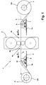
- FIG. 1 The one shown in FIG. 1 that can be operated in reverse operation Device 1 for cold rolling a steel strip S is with an unwinder 2, a first Strip tension compensation device 3, a roll stand 4, one second band tension compensation device 5 and one Rewinder 6 equipped.
- the Unwinder 2, the first Belt tension compensation device 3, the roll stand 4, the second band tension compensation device 5 and Rewinder 6 are placed in line and are from the cold-rolled steel strip S in the conveying direction F happened in succession.
- the band tension compensation devices 3.5 each comprise a car 7.8.
- Each of the carriages 7,8 can be set up independently rails 7a, 8a arranged in a horizontal plane by means of each of a suitable drive linear between the Roll stand 4 and the unwinder 2 and the Roll stand 4 and the winding device 6 move become.
- the carriages 7,8 each carry a role 9,10, the Axis of rotation essentially parallel to the axis of rotation the work rolls of the roll stand 4 is aligned.
- the position of the axis of rotation of the roller 3 is oriented taking into account their diameter, that the steel strip S between the roll 3 and the roll gap 4a of the roll stand 4 in a constant through which Rolling gap 4a running horizontal plane H runs.
- Steel strip S is on the roll 10 of the second Belt tension compensation device 5 deflected lying thereon, that it is from below into the take-up device 6 wound coil CB runs in.
- the position of the Axis of rotation of the roller 10 of the second Belt tension compensation device 5 is aligned so that the steel strip S between the roll stand 4 and the Roll 10 runs in the horizontal plane H.
- Both role 9 and role 10 are from Steel belt S wrapped around less than 90 ° of its circumference.
- the band tension compensation device 3 in the direction of Roll stand 4 moves.
- the Strip tension compensation device 3 goes to the roll stand 4 a shortening of the distance between the Coil CA and the roll stand free running tape length.
- the position in question the band tension compensation device 3 is in FIG. 1 shown in dashed lines.
- the device 20 shown in FIG. 2 corresponds in terms of their functional units and the way they work the band tension compensation devices 3.5 of the previous Device 1 explained.
- a deflection roller 11 arranged in the device 20 between the Unwinding device 2 and the associated Belt tension compensation device 3 .
- the deflection roller 11 is so on the one hand positions that the steel strip S at maximum diameter of the coil CA essentially runs horizontally from below to the pulley 11 and then is deflected upwards at her so that it is on the Coil CA side facing the roll 9 of the Bandzugaustechnischs owned 3, where it then hits again in the horizontal plane H in the direction of Roll gap 4a of the roll stand 4 is deflected.
- Through the Deflection roller 11 is thus ensured that the steel strip S even with large diameters of the coil CA in enters the conveyor path of the device 20.
- the device 20 is between the band tension compensation device 5 and the Winding device 6 a deflection roller 12 is provided. Also this deflection roller 12 is positioned so that the Steel strip wound on the Coil CB with maximum circumference of the coil CB is guided essentially horizontally.
- steel strip S is first on roll 10 the band tension compensation device 5 deflected such that it on the side assigned to the roll stand 4 on the Deflection roller 12 hits. The steel strip S is then attached to it again directed towards the coil CB.
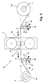
- the device 30 shown in FIG. 3 also corresponds in its basic concept that shown in Fig. 1 Device 1. It is accordingly also with a Winding device 2, a first Belt tension compensation device 33, a roll stand 4, one second band tension compensation device 35 and one Rewinder 6 equipped in the conveying direction F in line from the cold to be rolled Steel belt S are run through.
- the strip tension compensation devices 33,35 each formed by a rocker 36 and 37, respectively one end each parallel to the axis Rotation axes of the roll stand aligned pivot axis 38.39 are pivotally mounted.
- the swivel actuation takes place thereby by hydraulic cylinder 40.41.
- other drive types can also be used for this purpose use that have a comparably fast response time and ensure a sufficiently high generation of force.
- each rocker 36, 37 carries one Roll 9.10.
- the length of the wings 36.37 is below Taking into account the diameter of each of them worn roll 9.10 dimensioned so that with vertical Alignment of the wings 36,37 the steel strip S between the rollers 9, 10 and the roll gap 4a of the roll stand 4 in the horizontal plane H running through the roll gap 4a is led.
- the vertical position corresponds the respective middle position around which the wings 36, 37 be pivoted during the rolling operation.
- the rocker 37 is in the direction the winding device 6 moves when in the outlet area 4c of the roll stand 4 there is too little strip tension.
- the distance between the roller 10 carried by the rocker 37 and the roll stand and in turn the associated between the Coil CB and the mill stand 4 increased free running length of strip, so that after a sufficiently wide swiveling also in Infeed area 4c of the roll stand 4 the required Belt tension is restored.
Landscapes
- Engineering & Computer Science (AREA)
- Mechanical Engineering (AREA)
- Metal Rolling (AREA)
- Winding, Rewinding, Material Storage Devices (AREA)
- Control Of Metal Rolling (AREA)
Abstract
Description
- Fig. 1
- eine Vorrichtung zum Kaltwalzen von Stahlbändern in seitlicher Ansicht;
- Fig. 2
- eine Ausgestaltung der in Fig. 1 dargestellten Vorrichtung in seitlicher Ansicht;
- Fig. 3
- eine weitere Vorrichtung zum Kaltwalzen von Stahlbändern in seitlicher Ansicht.
- 1,20,30
- Vorrichtung zum Kaltwalzen eines Stahlbands
- 2
- Abwickeleinrichtung
- 3
- erste Bandzugausgleichseinrichtung
- 4
- Walzgerüst
- 4a
- Walzspalt des Walzgerüstes 4
- 4b
- Einlaufbereich des Walzgerüstes 4
- 4c
- Auslaufbereich des Walzgerüstes 4
- 5
- zweite Bandzugausgleichseinrichtung
- 6
- Aufwickeleinrichtung
- 7,8
- Wagen
- 7a,8a
- Schiene
- 9,10
- Rolle
- 11,12
- Umlenkrolle
- 33
- erste Bandzugausgleichseinrichtung
- 35
- zweite Bandzugausgleichseinrichtung
- 36,37
- Schwinge
- 38,39
- Schwenkachse
- 40,41
- Hydraulikzylinder
- S
- Stahlband
- F
- Förderrichtung
- CA
- Coil
- CB
- Coil
- H
- Horizontalebene
Claims (12)
- Vorrichtung zum Walzen von Metallbändern, insbesondere von Stahlbändern (S), mit einem Walzgerüst (4), mit einer Wickeleinrichtung (2,6) und mit mindestens einer zwischen dem Walzgerüst (4) und der Wickeleinrichtung (2,6) angeordneten Bandzugausgleichseinrichtung (3,5), dadurch gekennzeichnet, dass die Bandzugausgleichseinrichtung (3,5) eine das jeweils gewalzte Band (S) im Betrieb umlenkende Rolle (9,10) umfasst, deren in horizontaler Richtung gemessener Abstand vom Walzgerüst (4) verstellbar ist.
- Vorrichtung nach Anspruch 1, dadurch gekennzeichnet, dass, die Position der Rolle (9,10) in Horizontalrichtung linear verstellbar ist.
- Vorrichtung nach einem der voranstehenden Ansprüche, dadurch gekennzeichnet, dass die Rolle (9,10) von einem Wagen (7,8) getragen ist, der mittels eines Antriebs aus einer Stellung, in der ein erster Abstand zwischen der Rolle (9,10) und dem Walzgerüst (4) besteht, in mindestens eine zweiten Stellung verfahrbar ist, in der ein anderer Abstand zwischen der Rolle (9,10) und dem Walzgerüst (4) besteht.
- Vorrichtung nach einem der voranstehenden Ansprüche, dadurch gekennzeichnet, dass die Rolle (9,10) von einer Schwinge (36,37) getragen ist.
- Vorrichtung nach Anspruch 4, dadurch gekennzeichnet, dass die Schwenkachse (38,39) der Schwinge (36,37) achsparallel zu den Drehachsen der Arbeitswalze des Walzgerüstes (4) angeordnet ist.
- Vorrichtung nach einem der Ansprüche 4 oder 5, dadurch gekennzeichnet, dass die Länge der Schwinge (36,37) im Betrieb veränderbar ist.
- Vorrichtung nach einem der Ansprüche 4 bis 6, dadurch gekennzeichnet, dass die Schwinge (36,37) in einer Mittelstellung der von ihr im Betrieb ausgeführten Schwenkbewegungen im Wesentlichen senkrecht ausgerichtet ist.
- Vorrichtung nach einem der voranstehenden Ansprüche, dadurch gekennzeichnet, dass jeweils mindestens eine Bandzugausgleichseinrichtung (9,10) in Förderrichtung (F) des Metallbands (S) vor und hinter dem Walzgerüst (4) angeordnet ist.
- Vorrichtung nach einem der voranstehenden Ansprüche, dadurch gekennzeichnet, dass im Förderweg des Stahlbands (S) zwischen der Bandzugausgleichseinrichtung (3,5,33,35) und der Abwickel- oder der Aufwickeleinrichtung (2,6) mindestens eine Umlenkrolle (11,12) angeordnet ist.
- Vorrichtung nach einem der voranstehenden Ansprüche, dadurch gekennzeichnet, dass die Rolle (9,10) der Bandzugausgleichseinrichtung (3,5,33,35) und / oder die jeweils zusätzlich angeordneten Umlenkrollen (11,12) mit einem Antrieb oder einer Bremseinrichtung verkoppelt sind.
- Vorrichtung nach einem der voranstehenden Ansprüche, dadurch gekennzeichnet, dass das Walzgerüst (4) mit einer Stellvorrichtung ausgestattet ist, welche die Höhe des Walzspalts (4a) während des Betriebes derart verändert, dass das gewalzte Metallband (S) in einer Stellung eine geringe Banddicke und in einer anderen Stellung eine größere Banddicke erhält.
- Verfahren zum Walzen von Metallbändern, insbesondere zum Kaltwalzen von Stahlbändern (S), bei dem das zu walzende Metallband von einem Coil (CA) abgehaspelt, in einem Walzgerüst (4) gewalzt und anschließend aufgehaspelt wird, wobei der auf dem Metallband (S) lastende Bandzug mittels einer Bandzugausgleichseinrichtung (3,5,33,35) geregelt wird, deren horizontaler Abstand vom Walzgerüst (4) in Abhängigkeit vom jeweils erfassten Bandzug verstellt wird.
Applications Claiming Priority (2)
| Application Number | Priority Date | Filing Date | Title |
|---|---|---|---|
| DE2003110399 DE10310399B4 (de) | 2003-03-07 | 2003-03-07 | Vorrichtung und Verfahren zum Walzen von Metallbändern |
| DE10310399 | 2003-03-07 |
Publications (2)
| Publication Number | Publication Date |
|---|---|
| EP1454681A2 true EP1454681A2 (de) | 2004-09-08 |
| EP1454681A3 EP1454681A3 (de) | 2005-06-15 |
Family
ID=32797898
Family Applications (1)
| Application Number | Title | Priority Date | Filing Date |
|---|---|---|---|
| EP04001876A Ceased EP1454681A3 (de) | 2003-03-07 | 2004-01-29 | Vorrichtung und Verfahren zum Walzen von Metallbändern |
Country Status (2)
| Country | Link |
|---|---|
| EP (1) | EP1454681A3 (de) |
| DE (1) | DE10310399B4 (de) |
Cited By (8)
| Publication number | Priority date | Publication date | Assignee | Title |
|---|---|---|---|---|
| EP1464415A3 (de) * | 2003-04-03 | 2006-08-16 | Muhr und Bender KG | Verfahren zum Walzen und Walzanlage zum Walzen von Metallband |
| WO2006119998A1 (en) * | 2005-05-11 | 2006-11-16 | Corus Staal Bv | Method and apparatus for producing strip having a variable thickness |
| EP3210681A1 (de) * | 2016-02-23 | 2017-08-30 | BILSTEIN GmbH & Co. KG | Vorrichtung und verfahren zum walzen von bandmaterial mit veränderlicher banddicke |
| EP3610961A1 (de) * | 2018-08-15 | 2020-02-19 | Muhr und Bender KG | Vorrichtung, walzanlage und verfahren zum regeln eines bandzuges beim flexiblen walzen von metallband |
| WO2020114976A1 (de) * | 2018-12-06 | 2020-06-11 | Sms Group Gmbh | Verfahren zum betreiben eines walzgerüstes zum stufenwalzen |
| CN112517663A (zh) * | 2020-12-28 | 2021-03-19 | 江苏大力神科技股份有限公司 | 一种安装在轧辊后的压紧装置 |
| CN114761149A (zh) * | 2019-11-25 | 2022-07-15 | N·乌姆拉夫 | 轧制线 |
| CN115647080A (zh) * | 2022-11-21 | 2023-01-31 | 中国重型机械研究院股份公司 | 一种冷轧带钢长度补偿装置及方法 |
Families Citing this family (2)
| Publication number | Priority date | Publication date | Assignee | Title |
|---|---|---|---|---|
| DE102006047463A1 (de) * | 2006-10-07 | 2008-04-17 | ACHENBACH BUSCHHüTTEN GMBH | Walzwerk und Verfahren zum flexiblen Kalt- oder Warm- Einweg- oder Reversierwalzen von Metallband |
| US9566626B2 (en) * | 2013-12-04 | 2017-02-14 | Sms Group Gmbh | Apparatus for and method of winding-up a metal strip, and plant for producing a metal strip windable into a coil |
Family Cites Families (6)
| Publication number | Priority date | Publication date | Assignee | Title |
|---|---|---|---|---|
| JPS60231516A (ja) * | 1984-04-28 | 1985-11-18 | Sumitomo Metal Ind Ltd | ル−パ機構を有する巻取機 |
| JPS6289512A (ja) * | 1985-10-14 | 1987-04-24 | Kawasaki Steel Corp | 冷間圧延機の出側設備 |
| JPH033851A (ja) * | 1989-05-30 | 1991-01-09 | Kawasaki Steel Corp | ルーパの制御方法 |
| DE19818207C2 (de) * | 1998-04-23 | 2000-05-31 | Schloemann Siemag Ag | Steckel-Warmwalzwerk |
| DE10004532A1 (de) * | 2000-02-02 | 2001-08-30 | Josef Froehling Gmbh Walzwerks | Vorrichtung zum Walzen von Bändern mit periodisch veränderlicher Bandenddicke |
| DE10133756A1 (de) * | 2001-07-11 | 2003-01-30 | Sms Demag Ag | Kaltwalzwerk sowie Verfahren zum Kaltwalzen von metallischem Band |
-
2003
- 2003-03-07 DE DE2003110399 patent/DE10310399B4/de not_active Expired - Fee Related
-
2004
- 2004-01-29 EP EP04001876A patent/EP1454681A3/de not_active Ceased
Cited By (15)
| Publication number | Priority date | Publication date | Assignee | Title |
|---|---|---|---|---|
| US7185523B2 (en) | 2003-04-03 | 2007-03-06 | Muhr Und Bender Kg | Rolling process and rolling system for rolling metal strip |
| EP1464415A3 (de) * | 2003-04-03 | 2006-08-16 | Muhr und Bender KG | Verfahren zum Walzen und Walzanlage zum Walzen von Metallband |
| WO2006119998A1 (en) * | 2005-05-11 | 2006-11-16 | Corus Staal Bv | Method and apparatus for producing strip having a variable thickness |
| EP3210681A1 (de) * | 2016-02-23 | 2017-08-30 | BILSTEIN GmbH & Co. KG | Vorrichtung und verfahren zum walzen von bandmaterial mit veränderlicher banddicke |
| US11666957B2 (en) | 2018-08-15 | 2023-06-06 | Muhr Und Bender Kg | Controlling a strip tension during the flexible rolling of metal strip |
| EP3610961A1 (de) * | 2018-08-15 | 2020-02-19 | Muhr und Bender KG | Vorrichtung, walzanlage und verfahren zum regeln eines bandzuges beim flexiblen walzen von metallband |
| WO2020035261A1 (de) * | 2018-08-15 | 2020-02-20 | Muhr Und Bender Kg | Vorrichtung, walzanlage und verfahren zum regeln eines bandzuges beim flexiblen walzen von metallband |
| WO2020114976A1 (de) * | 2018-12-06 | 2020-06-11 | Sms Group Gmbh | Verfahren zum betreiben eines walzgerüstes zum stufenwalzen |
| CN113226580A (zh) * | 2018-12-06 | 2021-08-06 | Sms集团有限公司 | 用于操纵用来阶梯式轧制的轧机机架的方法 |
| US11701695B2 (en) | 2018-12-06 | 2023-07-18 | Sms Group Gmbh | Method for operating a roll stand for stepped rolling |
| CN113226580B (zh) * | 2018-12-06 | 2024-03-19 | Sms集团有限公司 | 用于操纵用来阶梯式轧制的轧机机架的方法 |
| CN114761149A (zh) * | 2019-11-25 | 2022-07-15 | N·乌姆拉夫 | 轧制线 |
| CN114761149B (zh) * | 2019-11-25 | 2024-03-15 | N·乌姆拉夫 | 轧制线 |
| CN112517663A (zh) * | 2020-12-28 | 2021-03-19 | 江苏大力神科技股份有限公司 | 一种安装在轧辊后的压紧装置 |
| CN115647080A (zh) * | 2022-11-21 | 2023-01-31 | 中国重型机械研究院股份公司 | 一种冷轧带钢长度补偿装置及方法 |
Also Published As
| Publication number | Publication date |
|---|---|
| EP1454681A3 (de) | 2005-06-15 |
| DE10310399B4 (de) | 2005-03-03 |
| DE10310399A1 (de) | 2004-09-23 |
Similar Documents
| Publication | Publication Date | Title |
|---|---|---|
| DE69528224T2 (de) | Gerät und Verfahren zum berührungslosen aktiven Spannen von sich bewegendem bandförmigem Material | |
| DE69403790T2 (de) | Verfahren und vorrichtung zum aufwickeln eines bandwickels | |
| EP1406735B1 (de) | Kaltwalzerk sowie verfahren zum kaltwalzen von metallischem band | |
| EP1278606B1 (de) | Verfahren und vorrichtung zum lagegerechten aufwickeln eines gewalzten warmbandes in einer haspelvorrichtung | |
| EP3210681B1 (de) | Vorrichtung und verfahren zum walzen von bandmaterial mit veränderlicher banddicke | |
| DE10315357B4 (de) | Verfahren zum Walzen und Walzanlage zum Walzen von Metallband | |
| EP1074317B1 (de) | Verfahren zum flexiblen Walzen eines Metallbandes | |
| DE102013002020B4 (de) | Wickelungsvorrichtung und Wickelungsverfahren für ein strangförmiges Wickelgut | |
| WO2010124969A1 (de) | Vorrichtung zur kompensation von zugschwankungen und/oder zur einstellung der zugspannung an einem geförderten flexiblen materialstrang | |
| EP2563533B1 (de) | Minimierung des bandzugs eines walzgutes zwischen zwei walzeinheiten | |
| EP1908534B1 (de) | Walzwerk und Verfahren zum flexiblen Kalt- oder Warm-Einweg- oder Reversierwalzen von Metallband | |
| DE10310399B4 (de) | Vorrichtung und Verfahren zum Walzen von Metallbändern | |
| DE69921179T2 (de) | Wickler und verfahren zum wickeln einer bahn | |
| WO2010020486A2 (de) | Verfahren zur einstellung einer zugspannung eines bandes, steuer- und/oder regeleinrichtung, speichermedium, programmcode zur durchführung des verfahrens und eine industrieanlage zum bearbeiten von band | |
| EP1121990B1 (de) | Vorrichtung zum Walzen von Bändern mit periodisch veränderlicher Banddicke | |
| EP1784266B1 (de) | Walzwerk zum walzen von metallischem band | |
| DE102012214803A1 (de) | Vorrichtung zur Übergabe von Metallband | |
| AT506493B1 (de) | Verfahren zum aufrollen einer papier- oder kartonbahn, und rollapparat | |
| EP0088347B2 (de) | Kettenzieh- und Kettenbremsvorrichtung zum Konstanthalten der Spannungen von Metallbändern | |
| DE19524729A1 (de) | Verfahren und Vorrichtung zum Walzen von Bändern mit über ihrer Breite ungleichförmige Dicken- und/oder Längenverteilung | |
| EP3610961B1 (de) | Vorrichtung, walzanlage und verfahren zum regeln eines bandzuges beim flexiblen walzen von metallband | |
| DE102020210970A1 (de) | Planheitsmessvorrichtung, Warmwalzanlage und Verfahren zum Betreiben einer Planheitsmessvorrichtung | |
| DE102020117682A1 (de) | Richtmaschine und Verfahren zum Richten eines Metallbandes oder eines flächigen Metallteils | |
| EP3873685B1 (de) | Walzlinie | |
| DE602004013164T2 (de) | Aufwickelvorrichtung für walzhalbzeuge |
Legal Events
| Date | Code | Title | Description |
|---|---|---|---|
| PUAI | Public reference made under article 153(3) epc to a published international application that has entered the european phase |
Free format text: ORIGINAL CODE: 0009012 |
|
| AK | Designated contracting states |
Kind code of ref document: A2 Designated state(s): AT BE BG CH CY CZ DE DK EE ES FI FR GB GR HU IE IT LI LU MC NL PT RO SE SI SK TR |
|
| AX | Request for extension of the european patent |
Extension state: AL LT LV MK |
|
| PUAL | Search report despatched |
Free format text: ORIGINAL CODE: 0009013 |
|
| AK | Designated contracting states |
Kind code of ref document: A3 Designated state(s): AT BE BG CH CY CZ DE DK EE ES FI FR GB GR HU IE IT LI LU MC NL PT RO SE SI SK TR |
|
| AX | Request for extension of the european patent |
Extension state: AL LT LV MK |
|
| 17P | Request for examination filed |
Effective date: 20050804 |
|
| AKX | Designation fees paid |
Designated state(s): AT BE BG CH CY CZ DE DK EE ES FI FR GB GR HU IE IT LI LU MC NL PT RO SE SI SK TR |
|
| 17Q | First examination report despatched |
Effective date: 20051104 |
|
| STAA | Information on the status of an ep patent application or granted ep patent |
Free format text: STATUS: THE APPLICATION HAS BEEN REFUSED |
|
| 18R | Application refused |
Effective date: 20070106 |