EP1454699A1 - Verfahren und Vorrichtung zur Befestigung einer Kreuzgelenkgabel an einem Rohr mittels Magnetimpuls-Schweissen - Google Patents
Verfahren und Vorrichtung zur Befestigung einer Kreuzgelenkgabel an einem Rohr mittels Magnetimpuls-Schweissen Download PDFInfo
- Publication number
- EP1454699A1 EP1454699A1 EP03251360A EP03251360A EP1454699A1 EP 1454699 A1 EP1454699 A1 EP 1454699A1 EP 03251360 A EP03251360 A EP 03251360A EP 03251360 A EP03251360 A EP 03251360A EP 1454699 A1 EP1454699 A1 EP 1454699A1
- Authority
- EP
- European Patent Office
- Prior art keywords
- yoke arms
- providing
- magnetic pulse
- support apparatus
- pulse welding
- Prior art date
- Legal status (The legal status is an assumption and is not a legal conclusion. Google has not performed a legal analysis and makes no representation as to the accuracy of the status listed.)
- Withdrawn
Links
- 238000003466 welding Methods 0.000 title claims abstract description 40
- 238000000034 method Methods 0.000 title claims description 26
- 230000035939 shock Effects 0.000 abstract description 5
- 230000000644 propagated effect Effects 0.000 abstract description 4
- 239000007769 metal material Substances 0.000 description 6
- 239000004020 conductor Substances 0.000 description 5
- 238000005304 joining Methods 0.000 description 5
- 229910045601 alloy Inorganic materials 0.000 description 4
- 239000000956 alloy Substances 0.000 description 4
- 239000003990 capacitor Substances 0.000 description 4
- 230000005672 electromagnetic field Effects 0.000 description 4
- 229910052782 aluminium Inorganic materials 0.000 description 3
- XAGFODPZIPBFFR-UHFFFAOYSA-N aluminium Chemical compound [Al] XAGFODPZIPBFFR-UHFFFAOYSA-N 0.000 description 3
- 230000000712 assembly Effects 0.000 description 2
- 238000000429 assembly Methods 0.000 description 2
- 230000005540 biological transmission Effects 0.000 description 2
- 238000003780 insertion Methods 0.000 description 2
- 230000037431 insertion Effects 0.000 description 2
- 239000003562 lightweight material Substances 0.000 description 2
- 229910000755 6061-T6 aluminium alloy Inorganic materials 0.000 description 1
- 229910000831 Steel Inorganic materials 0.000 description 1
- 238000004581 coalescence Methods 0.000 description 1
- 238000004146 energy storage Methods 0.000 description 1
- 239000000945 filler Substances 0.000 description 1
- 230000014759 maintenance of location Effects 0.000 description 1
- 238000004519 manufacturing process Methods 0.000 description 1
- 239000000463 material Substances 0.000 description 1
- 229910052751 metal Inorganic materials 0.000 description 1
- 239000002184 metal Substances 0.000 description 1
- 239000010959 steel Substances 0.000 description 1
Images


Classifications
-
- B—PERFORMING OPERATIONS; TRANSPORTING
- B23—MACHINE TOOLS; METAL-WORKING NOT OTHERWISE PROVIDED FOR
- B23K—SOLDERING OR UNSOLDERING; WELDING; CLADDING OR PLATING BY SOLDERING OR WELDING; CUTTING BY APPLYING HEAT LOCALLY, e.g. FLAME CUTTING; WORKING BY LASER BEAM
- B23K20/00—Non-electric welding by applying impact or other pressure, with or without the application of heat, e.g. cladding or plating
- B23K20/06—Non-electric welding by applying impact or other pressure, with or without the application of heat, e.g. cladding or plating by means of high energy impulses, e.g. magnetic energy
Definitions
- This invention relates in general to the use of magnetic pulse welding techniques to secure two metallic components together, such as a yoke and a driveshaft tube in a vehicular driveshaft assembly.
- this invention relates to an improved apparatus that minimizes the amount of undesirable distortions that can result in a yoke or similar end fitting when a driveshaft tube is secured thereto by means of such a magnetic pulse welding operation.
- a drive train system for transmitting rotational power from an output shaft of an engine/transmission assembly to an input shaft of an axle assembly so as to rotatably drive one or more wheels of the vehicle.
- a typical vehicular drive train assembly includes a hollow cylindrical driveshaft tube having first and second end fittings (such as tube yokes) secured to the opposed ends thereof.
- the first end fitting forms a portion of a first universal joint, which provides a rotatable driving connection from the output shaft of the engine/transmission assembly to the driveshaft tube while accommodating a limited amount of angular misalignment between the rotational axes of these two shafts.
- the second end fitting forms a portion of a second universal joint, which provides a rotatable driving connection from the driveshaft tube to the input shaft of the axle assembly while accommodating a limited amount of angular misalignment between the rotational axes of these two shafts.
- Magnetic pulse welding is an alternative process that has been proposed to secure the first and second end fittings to the opposed ends of the driveshaft tube.
- a hollow driveshaft tube having an end portion and an end fitting having a neck portion are initially provided.
- the end portion of the driveshaft tube can be hollow to allow the neck portion of the end fitting to be disposed co-axially therein.
- the neck portion of the end fitting can be hollow to allow the end portion of the driveshaft tube to be disposed telescopically therein.
- an annular gap is provided between the end of the driveshaft tube and the neck portion of the end fitting.
- an electrical inductor is provided concentrically about or within the co-axially overlapping portions of the driveshaft tube and the end fitting.
- the inductor is energized to generate a magnetic field that either collapses the outer member inwardly into engagement with the inner member or expands the inner member outwardly into engagement with the outer member. In either event, the high velocity impact of the two members, as well as the large pressures exerted thereon, cause them to become permanently joined together.
- a typical end fitting includes a body portion having a pair of opposed yoke arms that extend therefrom in a first axial direction. A pair of aligned openings are formed through the yoke arms and are adapted to receive conventional bearing cups of the universal joint cross therein. A generally hollow neck portion extends axially in a second axial direction from the body portion.
- an end portion of the driveshaft tube is installed onto co-axially about the neck portion of the end fitting.
- the inductor is energized to generate an immense and momentary electromagnetic field about the end portion of the driveshaft tube.
- This electromagnetic field exerts a very large force on the outer surface of the end portion of the driveshaft tube, causing it to collapse inwardly at a high velocity onto the neck portion of the end fitting.
- the resulting impact of the inner surface of the end portion of the driveshaft tube with the outer surface of the neck portion of the end fitting causes a weld or molecular bond to occur therebetween.
- the high velocity impact of the end portion of the driveshaft tube onto the neck portion of the end fitting during the magnetic pulse welding operation can, in some instances, cause the yoke arms of the end fitting to be permanently deflected relative to one another.
- the end portion of the driveshaft tube is collapsed upon the neck portion of the end fitting, the inward deformation of the neck portion can cause the yoke arms on the other end of the end fitting to spread outwardly apart from one another.
- the shock wave propagated through the end fitting as a result of this impact can slightly enlarge the dimensions of the openings formed through the yoke arms.
- Such deflections of the yoke arms are undesirable because they can result in the misalignment of the respective openings formed therethrough.
- the openings formed through the yoke arms are not precisely aligned, it may be relatively difficult to properly install the remaining portions of the universal joint thereon and to balance the universal joint for rotation.
- This invention relates to an improved apparatus that minimizes the amount of undesirable distortions that can result in a yoke or similar end fitting when a driveshaft tube is secured thereto by a magnetic pulse welding operation.
- the support apparatus includes a lower jaw, an upper jaw, and a support pin extending therebetween. During the magnetic pulse welding operation, the lower and upper jaws of the support apparatus engage the opposed yoke arms, and the support pin extends through respective openings formed through the opposed yoke arms.
- the support apparatus can also include a counter die that is disposed between the lower jaw and the upper jaw and has an arcuate recess formed therein that receives the outer portions of the opposed yoke arms therein.
- the support apparatus can further include a pair of positioning rails that engage the body portion of the yoke. As a result, the support apparatus prevents deformation of the opposed yoke arms and absorbs shock waves that can be propagated through the yoke during the magnetic pulse welding operation.
- a vehicular driveshaft assembly 10 that includes a driveshaft tube, indicated generally at 20, and a first embodiment of an end fitting, indicated generally at 30.
- this invention will be described and illustrated in the context of securing an end fitting to a driveshaft tube to form a portion of a vehicular driveshaft assembly, it will be appreciated that the method of this invention can be used to secure any two metallic components together for any desired purpose or application.
- the illustrated driveshaft tube 20 is generally hollow and cylindrical in shape and can be formed from any desired metallic material, such as 6061 T6 aluminum alloy, for example.
- the driveshaft tube 20 has an outer surface that defines a substantially constant outer diameter and an inner surface that defines a substantially constant inner diameter.
- the illustrated driveshaft tube 20 has a substantially cylindrical and uniform wall thickness, although such is not required.
- the driveshaft tube 20 has an end portion 21 that terminates at an end surface 22.
- the illustrated end fitting 30 is a tube yoke formed from a metallic material that can be either the same as or different from the metallic material used to form the driveshaft tube 20, such steel or an alloy of aluminum, for example.
- the end fitting 30 includes a body portion 31 having a pair of opposed yoke arms 32 that extend therefrom in a first axial direction.
- a pair of aligned openings 33 are formed through the yoke arms 32 and are adapted to receive conventional bearing cups (not shown) of a universal joint cross therein.
- an annular groove 33a can be formed within each of the openings 33 to facilitate retention of the bearing cups therein in a known manner by means of respective snap rings (not shown).
- a generally hollow neck portion 34 extends axially in a second axial direction from the body portion 31.
- the structure of the neck portion 34 is described in detail in co-pending application Serial No. 60/362,215, filed March 6, 2002, which is owned by the assignee of this invention. The disclosure of that application is incorporated herein by reference.
- an annular groove 35 (see Fig. 2) or similar recessed area can be formed on the interior of the end fitting 30. The purpose for this annular groove 35 is explained in detail in co-pending application Serial 60/362,150, filed March 6, 2002, which is also owned by the assignee of this invention. The disclosure of that application is also incorporated herein by reference.
- Fig. 2 also illustrates an inductor 40 disposed about the assembly of the driveshaft tube 20 and the end fitting 30 prior to the performance of a magnetic pulse welding operation for securing the two components together in accordance with the method of this invention.
- the inductor 40 can be formed having any desired structure, such as that shown and described in U.S. Patent No. 4,129,846 to Yablochnikov. The disclosure of that patent is incorporated herein by reference.
- the inductor 40 is connected to a schematically illustrated control circuit for selectively operating same. As shown in Fig. 2, a first end of the inductor 40 is connected to a first electrical conductor 41, while a second end of the inductor 40 is connected through a discharge switch 42 to a second electrical conductor 43.
- a plurality of high voltage capacitors 44 or similar energy storage devices are connected between the first and second electrical conductors 41 and 43.
- the first electrical conductor 41 is also connected to a source of electrical energy 45, while the second electrical conductor 43 is connected through a charging switch 46 to the source of electrical energy 45.
- the structure and operation of the control circuit is described in detail in U.S. Patent No. 5,981,921 to Yablochnikov, and the disclosure of that patent is also incorporated herein by reference.
- the inductor 40 is operated by initially opening the discharge switch 42 and closing the charging switch 46. This allows electrical energy to be transferred from the source of electrical energy 45 to each of the capacitors 44. When the capacitors 44 have been charged to a predetermined voltage, the charging switch 46 is opened. Thereafter, when it is desired to operate the inductor 40, the discharge switch 42 is closed.
- the size and location of the weld region will vary with a variety of factors, such as the size of the gap 36, the size, shape, and nature of the metallic materials used to form the driveshaft tube 20 and the end fitting 30, the size and shape of the inductor 40, the angle and velocity of the impact between the end portion 21 of the driveshaft tube 20 and the neck portion 34 of the end fitting 30, and the like.
- the high velocity impact of the end portion 21 of the driveshaft tube 20 onto the neck portion of a conventional end fitting during the magnetic pulse welding operation can, at least in some instances, cause the yoke arms 32 of the end fitting 30 to be permanently deflected relative to one another.
- the body portion 31 of a conventional end fitting can be plastically deformed as a result of the impact of the end portion 21 of the driveshaft tube 20 on the neck portion 34.
- this high velocity impact can cause shock waves to propagate through the end fitting 30 from the neck portion 34 to the yoke arms 32 that can result in some distortion of the shape of the aligned openings 33 formed therethrough.
- an apparatus for supporting the end fitting 30 during the magnetic pulse welding operation.
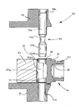
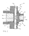
- the structure of the support apparatus 50 is illustrated in detail in Figs. 3, 4, and 5.
- the support apparatus 50 includes a lower jaw 51 having a bore 51a formed therethrough and an upper jaw 52 having a bore 52a formed therethrough.
- the lower jaw 51 and the upper jaw 52 are carried on a conventional support device (not shown) for movement relative to one another between an opened position (illustrated in Fig. 3) and a closed position (illustrated in Fig. 5).
- the lower jaw 51 and the upper jaw 52 are moved apart from one another to allow a workpiece, such as the end fitting 30, to be installed therein or removed therefrom, in the manner described in detail below.
- the closed position the lower jaw 51 and the upper jaw 52 are moved toward one another to engage and support the workpiece, such as the end fitting 30, during the magnetic pulse welding operation.
- the bores 5 1a and 52a are preferably co-axially aligned with one another.
- the support apparatus 50 also includes a support pin, indicated generally at 53.
- the illustrated support pin 53 includes an upper portion 53a that is sized to be press fit within the bore 52a formed through the upper jaw 52. However, the support pin 53 can be supported on the upper jaw 52 in any other conventional manner. Regardless, the support pin 53 is supported on the upper jaw 52 for movement therewith relative to the lower jaw 52, as described above.
- the illustrated support pin 53 also includes a lower portion 53b that is sized to be slightly smaller than the aligned openings 33 formed through the yoke arms 32 of the end fitting 30 and slightly smaller than the bore 51a formed through the lower jaw 51.
- the support pin 53 can be moved freely through the aligned openings 33 and through the bore 51a when the lower jaw 51 and the upper jaw 52 are moved from the opened position to the closed position, as described above.
- the support pin 53 may have a reduced diameter portion 53c between the upper portion 53a and the lower portion 53b. The purpose of this reduced diameter portion 53c will be explained below.
- the support pin 53 may have a chamfered end 53d provided on the lower portion 53b thereof to facilitate the insertion of the support pin 53 through such aligned openings 33 and through the bore 51a.
- the support pin 53 can be supported on the lower jaw 51 in a similar manner.
- the support pin 53 need not be supported on either of the jaws 51 and 52, but rather may be supported independently therefrom.
- the support apparatus 50 further includes a counter die 54 that is disposed between the lower jaw 51 and the upper jaw 52.
- the counter die 54 has an arcuate recess 54a formed therein that defines a pair of opposed counter die arms 54b.
- the counter die 54 may also include a pair of upstanding positioning rails 54c (see Fig. 4). If desired, the positioning rails 54c may be provided as separate members from the counter die 54, as shown in Fig. 4. The purpose for the counter die 54, the counter die arms 54b, and the positioning rails 54c will be explained below.
- the lower jaw 51 and the upper jaw 52 of the support apparatus 50 are moved to the opened position illustrated in Fig. 3.
- an end fitting 30 is loaded into the support apparatus 50 by disposing the end fitting 30 on the lower jaw 51 as shown in Figs. 3 and 4.
- the lower surface of the lower yoke arm 32 of the end fitting 30 engages the upper surface of the lower jaw 51.
- the openings 33a formed through the yoke arms 33 are aligned, at least approximately, with the bore 51a formed through the lower jaw 51 and the bore 52a formed through the upper jaw 52.
- the body portion 31 of the end fitting 30 engages the positioning rails 54c so as to be positively positioned relative thereto in a lateral direction (i.e., from top to bottom when viewing Fig. 4).
- the support apparatus 50 is actuated to move the lower jaw 51 and the upper jaw 52 of the support apparatus 50 to the closed position illustrated in Fig. 5.
- the support pin 53 is moved through the upper opening 33 formed through the upper yoke arm 32 of the end fitting 30, through the lower opening 33 formed through the lower yoke arm 32 of the end fitting 30, and into the bore 51a formed through the lower jaw 51.
- the chamfered end 53d of the support pin 53 accommodates any small amount of misalignment between the two openings 33 and the bore 51a to facilitate the insertion of the support pin 53 therethrough.
- the support pin 53 is preferably formed from a hardened material such that when it is inserted through the openings 33 of the yoke arms 32, any misalignment therebetween is automatically corrected. Because of the lack of any significant resistance, this initial movement of the jaws 51 and 52 toward the closed position can be accomplished at a relatively fast speed.
- the support apparatus 50 When the lower surface of the upper jaw 52 engages the upper surface of the upper yoke arm 32 of the end fitting 30, the support apparatus 50 is in the closed position. Thus, further relative movement of the lower and upper jaws 51 and 52 can be ceased. However, it may be desirable for the support apparatus 50 to exert a preloading force against the yoke arms 32 of the end fitting 30 prior to the commencement of the magnetic pulse welding operation. To accomplish this, the support apparatus 50 can be operated such that the lower and upper jaws 51 and 52 slightly compress the yoke arms 32 of the end fitting 30 therebetween. As a result, the yoke arms 32 are slightly flexed inwardly toward one another.
- the reduced diameter portion 53c of the support pin 53 provides a relatively weakened area therein that can accommodate such flexing of the yoke arms 32. Accordingly, the end fitting 30 is securely engaged and supported by the support apparatus 50 in the axial direction (by means of the support pin 53 extending through the openings of the yoke arms 32), in the lateral direction (by means of the positioning rails 54c engaging the body portion 31 of the end fitting 30), and in the vertical direction (by means of the lower and upper jaws 51 and 52 engaging the body portion 31 of the end fitting 30).
- the counter die 54 is actuated to move axially toward the end fitting 30 until the outer portions of the yoke arms 32 are received within the arcuate recess 54a formed therein.
- the yoke arms 32 of the end fitting 30 engage the opposed counter die arms 54b so as to be positively positioned relative thereto in the axial direction (i.e., from left to right when viewing Fig. 4).
- the counter die 54 provides additional support in the axial direction for the end fitting 30.
- the inductor 40 is energized to perform the magnetic pulse welding operation as described above.
- the high velocity impact of the end portion 21 of the driveshaft tube 20 onto the neck portion 34 of the end fitting 30 during the magnetic pulse welding operation can, in some instances, cause the yoke arms 32 of the end fitting 30 to be permanently deflected relative to one another.
- the support apparatus 50 prevents the inward deformation of the neck portion 34 during the magnetic pulse welding operation from causing the yoke arms 32 on the other end of the end fitting 30 to spread outwardly apart from one another.
- the support apparatus 50 absorbs the shock wave that is propagated through the end fitting 30 as a result of this impact to reduce or eliminate any enlargement of the dimensions of the openings 33 formed through the yoke arms 32.
Landscapes
- Engineering & Computer Science (AREA)
- Mechanical Engineering (AREA)
- Pressure Welding/Diffusion-Bonding (AREA)
- Shafts, Cranks, Connecting Bars, And Related Bearings (AREA)
Applications Claiming Priority (2)
| Application Number | Priority Date | Filing Date | Title |
|---|---|---|---|
| US36193802P | 2002-03-06 | 2002-03-06 | |
| US361938P | 2002-03-06 |
Publications (1)
| Publication Number | Publication Date |
|---|---|
| EP1454699A1 true EP1454699A1 (de) | 2004-09-08 |
Family
ID=27805095
Family Applications (1)
| Application Number | Title | Priority Date | Filing Date |
|---|---|---|---|
| EP03251360A Withdrawn EP1454699A1 (de) | 2002-03-06 | 2003-03-06 | Verfahren und Vorrichtung zur Befestigung einer Kreuzgelenkgabel an einem Rohr mittels Magnetimpuls-Schweissen |
Country Status (8)
| Country | Link |
|---|---|
| US (1) | US6908023B2 (de) |
| EP (1) | EP1454699A1 (de) |
| JP (1) | JP2004130384A (de) |
| CN (1) | CN1449885A (de) |
| AU (1) | AU2003200874A1 (de) |
| BR (1) | BR0302157A (de) |
| CA (1) | CA2421004A1 (de) |
| MX (1) | MXPA03001977A (de) |
Families Citing this family (11)
| Publication number | Priority date | Publication date | Assignee | Title |
|---|---|---|---|---|
| FR2822104B1 (fr) * | 2001-03-15 | 2003-06-13 | Vallourec Vitry | Fixation perfectionnee d'une traverse et de bras, notamment dabs un essieu semi-rigide |
| US6908023B2 (en) * | 2002-03-06 | 2005-06-21 | Torque-Traction Technologies, Inc. | Apparatus for securing a yoke to a tube using magnetic pulse welding techniques |
| US6817511B2 (en) * | 2002-12-16 | 2004-11-16 | Dana Corporation | Method for joining axle components |
| WO2006058241A1 (en) * | 2004-11-24 | 2006-06-01 | Dana Corporation | Method for performing a magnetic pulse welding operation to secure first and second metallic components with a preheating step for softening a first part of the first member |
| US20070218300A1 (en) * | 2006-03-14 | 2007-09-20 | Helmick David A | Method of applying a coating to an article via magnetic pulse welding |
| US9028164B2 (en) | 2012-03-08 | 2015-05-12 | Dana Automotive Systems Group, Llc | Magnetic pulse formed vehicle driveshaft and method of making same |
| US9553296B1 (en) | 2012-03-23 | 2017-01-24 | Greatbatch Ltd. | Magnetic pulse welding in medical power manufacturing |
| USD713302S1 (en) * | 2013-06-03 | 2014-09-16 | Mark Williams Enterprises, Inc. | Drive train yoke |
| CN104202903B (zh) * | 2014-09-10 | 2017-05-24 | 西北核技术研究所 | 平面金属薄膜负载装置 |
| FR3026037B1 (fr) * | 2014-09-23 | 2017-03-10 | Adm28 S Ar L | Bobine pour soudage de pieces tubulaires par impulsion magnetique et procede de soudage associe |
| CN116493724B (zh) * | 2023-06-21 | 2024-01-09 | 北京理工大学深圳汽车研究院(电动车辆国家工程实验室深圳研究院) | 一种磁脉冲焊接设备 |
Citations (3)
| Publication number | Priority date | Publication date | Assignee | Title |
|---|---|---|---|---|
| FR2450145A1 (fr) * | 1979-03-02 | 1980-09-26 | Angenieux Clb Sa | Procede d'assemblage des elements composant les cadres de bicyclettes et vehicules similaires, ainsi que les organes et les moyens correspondants de mise en oeuvre |
| US5981921A (en) * | 1997-06-20 | 1999-11-09 | Dana Corporation | Method of magnetic pulse welding an end fitting to a driveshaft tube of a vehicular driveshaft |
| US20020003159A1 (en) * | 2000-04-26 | 2002-01-10 | Gianfranco Gabbianelli | Hydroforming a tubular structure of varying diameter from a tubular blank made using electromagnetic pulse welding |
Family Cites Families (34)
| Publication number | Priority date | Publication date | Assignee | Title |
|---|---|---|---|---|
| US2341084A (en) * | 1940-05-11 | 1944-02-08 | Borg Warner | Constant velocity universal joint |
| US2478890A (en) * | 1946-12-10 | 1949-08-16 | Alfred T Barager | Flexible shaft coupling |
| US3092165A (en) * | 1961-01-11 | 1963-06-04 | Gen Dynamics Corp | Magnetic forming method and apparatus therefor |
| US3214511A (en) * | 1963-12-23 | 1965-10-26 | Westinghouse Electric Corp | Casing and insulator bushing assembly |
| US3520049A (en) * | 1965-10-14 | 1970-07-14 | Dmitry Nikolaevich Lysenko | Method of pressure welding |
| US3528596A (en) * | 1966-09-30 | 1970-09-15 | Us Army | Apparatus for pulse forming |
| US3417456A (en) * | 1966-09-30 | 1968-12-24 | Army Usa | Method for pulse forming |
| US3961739A (en) * | 1972-04-17 | 1976-06-08 | Grumman Aerospace Corporation | Method of welding metals using stress waves |
| US3992120A (en) * | 1975-03-13 | 1976-11-16 | Recker Florian B | Shaft coupling |
| US4129846A (en) * | 1975-08-13 | 1978-12-12 | Yablochnikov B | Inductor for magnetic pulse working of tubular metal articles |
| US4067216A (en) * | 1976-04-12 | 1978-01-10 | Lev Timofeevich Khimenko | Inductor for magnetic pulse shaping of metals |
| FR2464424A1 (fr) * | 1979-09-03 | 1981-03-06 | Aerospatiale | Procede pour munir une canalisation d'un embout de raccord et canalisation ainsi obtenue |
| US4523872A (en) * | 1981-08-12 | 1985-06-18 | Grumman Aerospace Corporation | Torsion resistant grooved joint |
| US4513188A (en) * | 1981-10-20 | 1985-04-23 | Jack Katzenstein | System and method for impact welding by magnetic implosion |
| US4504714A (en) * | 1981-11-02 | 1985-03-12 | Jack Katzenstein | System and method for impact welding by magnetic propulsion |
| US4551118A (en) * | 1984-03-05 | 1985-11-05 | Burroughs Corporation | Coupled drive shaft |
| JPS63502571A (ja) * | 1986-03-06 | 1988-09-29 | インスティチュト エレクトロスバルキ イメニ イ−.オ−.パトナ アカデミイ ナウク ウクラインスコイ エスエスア−ル | 磁気放電溶接用の円筒加工片整合器具 |
| US4702543A (en) * | 1986-04-30 | 1987-10-27 | G & H Technology, Inc. | Environmental seal and alignment means for an electromagnetically formed backshell |
| DE3779639D1 (de) * | 1987-03-19 | 1992-07-09 | Inst Elektroswarki Patona | Entladungsanordnung fuer magneto-pulsierungen bei der behandlung und beim schweissen von metallen. |
| US4807351A (en) * | 1988-02-18 | 1989-02-28 | Asea Composites, Inc. | Method for attaching an end-fitting to a drive shaft tube |
| US4930204A (en) * | 1989-02-01 | 1990-06-05 | A. O. Smith Corporation | Method of forming composite tubular structure |
| DE3943535C2 (de) * | 1989-06-24 | 1994-11-24 | Gkn Automotive Ag | Verbindungsanordnung |
| US5318374A (en) * | 1992-09-23 | 1994-06-07 | The Boeing Company | Composite tube structure |
| DE19602951C2 (de) * | 1996-01-27 | 2000-12-07 | Steingroever Magnet Physik | Verfahren und Vorrichtung zum Aufweiten von Rohren oder rohrförmigen Teilen durch das Magnetfeld eines Strom-Impulses |
| US5716276A (en) * | 1996-09-03 | 1998-02-10 | Dana Corporation | Yoke shaft for a vehicular driveshaft assembly |
| US6379254B1 (en) * | 1997-06-20 | 2002-04-30 | Spicer Driveshaft, Inc. | End fitting adapted to be secured to driveshaft tube by electromagnetic pulse welding |
| US6548791B2 (en) * | 2000-03-03 | 2003-04-15 | Inli, Llc | Energy storage apparatus and inductor tools for magnetic pulse welding and forming |
| US6400538B1 (en) * | 2000-03-03 | 2002-06-04 | Inli, Llc | Energy storage apparatus for magnetic pulse welding and forming |
| US6348670B2 (en) * | 2000-03-03 | 2002-02-19 | Inli, Llc | Energy storage apparatus and discharge device for magnetic pulse welding and forming |
| US6426249B1 (en) * | 2000-03-16 | 2002-07-30 | International Business Machines Corporation | Buried metal dual damascene plate capacitor |
| US6367680B1 (en) * | 2000-08-10 | 2002-04-09 | Spicer Driveshaft, Inc. | Component for vehicular driveshaft assembly and method of manufacturing same |
| US6908023B2 (en) * | 2002-03-06 | 2005-06-21 | Torque-Traction Technologies, Inc. | Apparatus for securing a yoke to a tube using magnetic pulse welding techniques |
| US6910617B2 (en) * | 2002-03-06 | 2005-06-28 | Torque-Traction Technologies, Inc. | Method for securing a yoke to a tube using magnetic pulse welding techniques |
| US6892929B2 (en) * | 2002-03-06 | 2005-05-17 | Torque-Traction Technologies, Inc. | Yoke structure that is adapted to be secured to a tube using magnetic pulse welding techniques |
-
2003
- 2003-03-05 US US10/382,110 patent/US6908023B2/en not_active Expired - Fee Related
- 2003-03-06 CN CN03136003A patent/CN1449885A/zh active Pending
- 2003-03-06 JP JP2003060371A patent/JP2004130384A/ja not_active Withdrawn
- 2003-03-06 MX MXPA03001977A patent/MXPA03001977A/es unknown
- 2003-03-06 AU AU2003200874A patent/AU2003200874A1/en not_active Abandoned
- 2003-03-06 EP EP03251360A patent/EP1454699A1/de not_active Withdrawn
- 2003-03-06 CA CA002421004A patent/CA2421004A1/en not_active Abandoned
- 2003-03-06 BR BR0302157-2A patent/BR0302157A/pt not_active Application Discontinuation
Patent Citations (3)
| Publication number | Priority date | Publication date | Assignee | Title |
|---|---|---|---|---|
| FR2450145A1 (fr) * | 1979-03-02 | 1980-09-26 | Angenieux Clb Sa | Procede d'assemblage des elements composant les cadres de bicyclettes et vehicules similaires, ainsi que les organes et les moyens correspondants de mise en oeuvre |
| US5981921A (en) * | 1997-06-20 | 1999-11-09 | Dana Corporation | Method of magnetic pulse welding an end fitting to a driveshaft tube of a vehicular driveshaft |
| US20020003159A1 (en) * | 2000-04-26 | 2002-01-10 | Gianfranco Gabbianelli | Hydroforming a tubular structure of varying diameter from a tubular blank made using electromagnetic pulse welding |
Also Published As
| Publication number | Publication date |
|---|---|
| CN1449885A (zh) | 2003-10-22 |
| BR0302157A (pt) | 2004-08-17 |
| CA2421004A1 (en) | 2003-09-06 |
| AU2003200874A1 (en) | 2003-09-25 |
| US20030218051A1 (en) | 2003-11-27 |
| JP2004130384A (ja) | 2004-04-30 |
| MXPA03001977A (es) | 2004-04-05 |
| US6908023B2 (en) | 2005-06-21 |
Similar Documents
| Publication | Publication Date | Title |
|---|---|---|
| US6892929B2 (en) | Yoke structure that is adapted to be secured to a tube using magnetic pulse welding techniques | |
| US6891137B2 (en) | Method of magnetic pulse welding an end fitting to a driveshaft tube of a vehicular driveshaft | |
| US5981921A (en) | Method of magnetic pulse welding an end fitting to a driveshaft tube of a vehicular driveshaft | |
| US20060131300A1 (en) | Method for performing a magnetic pulse welding operation | |
| US7140530B2 (en) | Method for joining axle components | |
| US6908023B2 (en) | Apparatus for securing a yoke to a tube using magnetic pulse welding techniques | |
| EP1949998B1 (de) | Verfahren zum Sichern eines Trägerstücks an einem Rohr mittels magnetischen Impulsschweißtechniken | |
| US6860013B1 (en) | Method for joining suspension components | |
| US20060144903A1 (en) | Method of manufacturing a combined driveshaft tube and yoke assembly | |
| US7181846B2 (en) | Method of manufacturing a combined driveshaft tube and yoke assembly | |
| US20050003897A1 (en) | Method of manufacturing a combined driveshaft tube and yoke assembly | |
| US6561722B1 (en) | Method of fabricating structural joints | |
| EP1710468A1 (de) | Verfahren zum Auswuchten eines Artikels für Drehungen | |
| AU763768B2 (en) | Method of magnetic pulse welding an end fitting to a driveshaft tube of a vehicular driveshaft |
Legal Events
| Date | Code | Title | Description |
|---|---|---|---|
| PUAI | Public reference made under article 153(3) epc to a published international application that has entered the european phase |
Free format text: ORIGINAL CODE: 0009012 |
|
| AK | Designated contracting states |
Kind code of ref document: A1 Designated state(s): AT BE BG CH CY CZ DE DK EE ES FI FR GB GR HU IE IT LI LU MC NL PT RO SE SI SK TR |
|
| AX | Request for extension of the european patent |
Extension state: AL LT LV MK |
|
| 17P | Request for examination filed |
Effective date: 20050302 |
|
| AKX | Designation fees paid |
Designated state(s): AT BE BG CH CY CZ DE DK EE ES FI FR GB GR HU IE IT LI LU MC NL PT RO SE SI SK TR |
|
| 17Q | First examination report despatched |
Effective date: 20050929 |
|
| STAA | Information on the status of an ep patent application or granted ep patent |
Free format text: STATUS: THE APPLICATION IS DEEMED TO BE WITHDRAWN |
|
| 18D | Application deemed to be withdrawn |
Effective date: 20061230 |