EP1454735A2 - Vorrichtung zur Herstellung von Beuteln und Verbundfolie - Google Patents
Vorrichtung zur Herstellung von Beuteln und Verbundfolie Download PDFInfo
- Publication number
- EP1454735A2 EP1454735A2 EP04251270A EP04251270A EP1454735A2 EP 1454735 A2 EP1454735 A2 EP 1454735A2 EP 04251270 A EP04251270 A EP 04251270A EP 04251270 A EP04251270 A EP 04251270A EP 1454735 A2 EP1454735 A2 EP 1454735A2
- Authority
- EP
- European Patent Office
- Prior art keywords
- former
- film
- layer
- laminated film
- former top
- Prior art date
- Legal status (The legal status is an assumption and is not a legal conclusion. Google has not performed a legal analysis and makes no representation as to the accuracy of the status listed.)
- Granted
Links
- 238000004519 manufacturing process Methods 0.000 title claims abstract description 29
- 230000004888 barrier function Effects 0.000 claims abstract description 62
- 230000003746 surface roughness Effects 0.000 claims abstract description 21
- 238000004806 packaging method and process Methods 0.000 claims abstract description 16
- 229920000642 polymer Polymers 0.000 claims description 48
- 238000000034 method Methods 0.000 claims description 29
- 239000005026 oriented polypropylene Substances 0.000 claims description 7
- QVGXLLKOCUKJST-UHFFFAOYSA-N atomic oxygen Chemical compound [O] QVGXLLKOCUKJST-UHFFFAOYSA-N 0.000 abstract description 9
- 230000005540 biological transmission Effects 0.000 abstract description 9
- 229910052760 oxygen Inorganic materials 0.000 abstract description 9
- 239000001301 oxygen Substances 0.000 abstract description 9
- 239000010408 film Substances 0.000 description 133
- 239000010410 layer Substances 0.000 description 109
- 239000007789 gas Substances 0.000 description 22
- -1 polypropylene Polymers 0.000 description 11
- 230000008569 process Effects 0.000 description 9
- 229920005989 resin Polymers 0.000 description 9
- 239000011347 resin Substances 0.000 description 9
- 229910052782 aluminium Inorganic materials 0.000 description 8
- XAGFODPZIPBFFR-UHFFFAOYSA-N aluminium Chemical compound [Al] XAGFODPZIPBFFR-UHFFFAOYSA-N 0.000 description 8
- 230000003287 optical effect Effects 0.000 description 8
- 239000004743 Polypropylene Substances 0.000 description 7
- 230000015572 biosynthetic process Effects 0.000 description 7
- 238000004364 calculation method Methods 0.000 description 7
- 229920001155 polypropylene Polymers 0.000 description 7
- 238000012360 testing method Methods 0.000 description 7
- 238000005452 bending Methods 0.000 description 6
- 239000000463 material Substances 0.000 description 6
- 229920006378 biaxially oriented polypropylene Polymers 0.000 description 5
- 239000011127 biaxially oriented polypropylene Substances 0.000 description 5
- 239000011248 coating agent Substances 0.000 description 5
- 238000000576 coating method Methods 0.000 description 5
- 238000013461 design Methods 0.000 description 5
- 230000006866 deterioration Effects 0.000 description 5
- 229910052751 metal Inorganic materials 0.000 description 5
- 239000002184 metal Substances 0.000 description 5
- 239000004698 Polyethylene Substances 0.000 description 4
- 208000028659 discharge Diseases 0.000 description 4
- 238000005259 measurement Methods 0.000 description 4
- 229920000098 polyolefin Polymers 0.000 description 4
- 239000004033 plastic Substances 0.000 description 3
- 229920003023 plastic Polymers 0.000 description 3
- 229920000573 polyethylene Polymers 0.000 description 3
- 229920005672 polyolefin resin Polymers 0.000 description 3
- 239000007787 solid Substances 0.000 description 3
- CSCPPACGZOOCGX-UHFFFAOYSA-N Acetone Chemical compound CC(C)=O CSCPPACGZOOCGX-UHFFFAOYSA-N 0.000 description 2
- YCKRFDGAMUMZLT-UHFFFAOYSA-N Fluorine atom Chemical compound [F] YCKRFDGAMUMZLT-UHFFFAOYSA-N 0.000 description 2
- VYPSYNLAJGMNEJ-UHFFFAOYSA-N Silicium dioxide Chemical compound O=[Si]=O VYPSYNLAJGMNEJ-UHFFFAOYSA-N 0.000 description 2
- NRTOMJZYCJJWKI-UHFFFAOYSA-N Titanium nitride Chemical compound [Ti]#N NRTOMJZYCJJWKI-UHFFFAOYSA-N 0.000 description 2
- 238000004458 analytical method Methods 0.000 description 2
- 238000006243 chemical reaction Methods 0.000 description 2
- 230000007547 defect Effects 0.000 description 2
- 239000003814 drug Substances 0.000 description 2
- 238000002474 experimental method Methods 0.000 description 2
- 229910052731 fluorine Inorganic materials 0.000 description 2
- 239000011737 fluorine Substances 0.000 description 2
- 235000013305 food Nutrition 0.000 description 2
- 238000009499 grossing Methods 0.000 description 2
- 239000005001 laminate film Substances 0.000 description 2
- 238000010030 laminating Methods 0.000 description 2
- 239000005022 packaging material Substances 0.000 description 2
- 239000002245 particle Substances 0.000 description 2
- 239000003208 petroleum Substances 0.000 description 2
- 229920005633 polypropylene homopolymer resin Polymers 0.000 description 2
- 229920001343 polytetrafluoroethylene Polymers 0.000 description 2
- 239000004810 polytetrafluoroethylene Substances 0.000 description 2
- 238000012545 processing Methods 0.000 description 2
- 239000002356 single layer Substances 0.000 description 2
- 238000004381 surface treatment Methods 0.000 description 2
- 239000001993 wax Substances 0.000 description 2
- 238000004804 winding Methods 0.000 description 2
- OKTJSMMVPCPJKN-UHFFFAOYSA-N Carbon Chemical compound [C] OKTJSMMVPCPJKN-UHFFFAOYSA-N 0.000 description 1
- 244000137852 Petrea volubilis Species 0.000 description 1
- SMEGJBVQLJJKKX-HOTMZDKISA-N [(2R,3S,4S,5R,6R)-5-acetyloxy-3,4,6-trihydroxyoxan-2-yl]methyl acetate Chemical compound CC(=O)OC[C@@H]1[C@H]([C@@H]([C@H]([C@@H](O1)O)OC(=O)C)O)O SMEGJBVQLJJKKX-HOTMZDKISA-N 0.000 description 1
- 229940081735 acetylcellulose Drugs 0.000 description 1
- 239000002390 adhesive tape Substances 0.000 description 1
- 230000004075 alteration Effects 0.000 description 1
- PNEYBMLMFCGWSK-UHFFFAOYSA-N aluminium oxide Inorganic materials [O-2].[O-2].[O-2].[Al+3].[Al+3] PNEYBMLMFCGWSK-UHFFFAOYSA-N 0.000 description 1
- 229910052799 carbon Inorganic materials 0.000 description 1
- 229920002301 cellulose acetate Polymers 0.000 description 1
- 239000003795 chemical substances by application Substances 0.000 description 1
- 238000005094 computer simulation Methods 0.000 description 1
- 238000004320 controlled atmosphere Methods 0.000 description 1
- 238000001816 cooling Methods 0.000 description 1
- 230000003247 decreasing effect Effects 0.000 description 1
- 238000009826 distribution Methods 0.000 description 1
- BXKDSDJJOVIHMX-UHFFFAOYSA-N edrophonium chloride Chemical compound [Cl-].CC[N+](C)(C)C1=CC=CC(O)=C1 BXKDSDJJOVIHMX-UHFFFAOYSA-N 0.000 description 1
- 238000005429 filling process Methods 0.000 description 1
- 239000011521 glass Substances 0.000 description 1
- 230000006872 improvement Effects 0.000 description 1
- 229910044991 metal oxide Inorganic materials 0.000 description 1
- 150000004706 metal oxides Chemical class 0.000 description 1
- 239000011104 metalized film Substances 0.000 description 1
- 239000012785 packaging film Substances 0.000 description 1
- 229920006280 packaging film Polymers 0.000 description 1
- 239000012188 paraffin wax Substances 0.000 description 1
- 238000005498 polishing Methods 0.000 description 1
- 229920006267 polyester film Polymers 0.000 description 1
- 229920013716 polyethylene resin Polymers 0.000 description 1
- 239000000843 powder Substances 0.000 description 1
- 229920001384 propylene homopolymer Polymers 0.000 description 1
- 230000009467 reduction Effects 0.000 description 1
- 230000003252 repetitive effect Effects 0.000 description 1
- 238000004439 roughness measurement Methods 0.000 description 1
- 238000005488 sandblasting Methods 0.000 description 1
- 239000000377 silicon dioxide Substances 0.000 description 1
- 235000011888 snacks Nutrition 0.000 description 1
- 150000003505 terpenes Chemical class 0.000 description 1
- 235000007586 terpenes Nutrition 0.000 description 1
- 230000032258 transport Effects 0.000 description 1
- XLYOFNOQVPJJNP-UHFFFAOYSA-N water Chemical compound O XLYOFNOQVPJJNP-UHFFFAOYSA-N 0.000 description 1
- 230000037373 wrinkle formation Effects 0.000 description 1
- 230000037303 wrinkles Effects 0.000 description 1
Images



Classifications
-
- B—PERFORMING OPERATIONS; TRANSPORTING
- B29—WORKING OF PLASTICS; WORKING OF SUBSTANCES IN A PLASTIC STATE IN GENERAL
- B29C—SHAPING OR JOINING OF PLASTICS; SHAPING OF MATERIAL IN A PLASTIC STATE, NOT OTHERWISE PROVIDED FOR; AFTER-TREATMENT OF THE SHAPED PRODUCTS, e.g. REPAIRING
- B29C53/00—Shaping by bending, folding, twisting, straightening or flattening; Apparatus therefor
- B29C53/36—Bending and joining, e.g. for making hollow articles
- B29C53/38—Bending and joining, e.g. for making hollow articles by bending sheets or strips at right angles to the longitudinal axis of the article being formed and joining the edges
- B29C53/48—Bending and joining, e.g. for making hollow articles by bending sheets or strips at right angles to the longitudinal axis of the article being formed and joining the edges for articles of indefinite length, i.e. bending a strip progressively
- B29C53/52—Bending and joining, e.g. for making hollow articles by bending sheets or strips at right angles to the longitudinal axis of the article being formed and joining the edges for articles of indefinite length, i.e. bending a strip progressively using external forming surfaces, e.g. sleeves
-
- B—PERFORMING OPERATIONS; TRANSPORTING
- B29—WORKING OF PLASTICS; WORKING OF SUBSTANCES IN A PLASTIC STATE IN GENERAL
- B29C—SHAPING OR JOINING OF PLASTICS; SHAPING OF MATERIAL IN A PLASTIC STATE, NOT OTHERWISE PROVIDED FOR; AFTER-TREATMENT OF THE SHAPED PRODUCTS, e.g. REPAIRING
- B29C53/00—Shaping by bending, folding, twisting, straightening or flattening; Apparatus therefor
- B29C53/36—Bending and joining, e.g. for making hollow articles
- B29C53/38—Bending and joining, e.g. for making hollow articles by bending sheets or strips at right angles to the longitudinal axis of the article being formed and joining the edges
- B29C53/387—Bending and joining, e.g. for making hollow articles by bending sheets or strips at right angles to the longitudinal axis of the article being formed and joining the edges the joining being done from the inside
-
- B—PERFORMING OPERATIONS; TRANSPORTING
- B65—CONVEYING; PACKING; STORING; HANDLING THIN OR FILAMENTARY MATERIAL
- B65B—MACHINES, APPARATUS OR DEVICES FOR, OR METHODS OF, PACKAGING ARTICLES OR MATERIALS; UNPACKING
- B65B9/00—Enclosing successive articles, or quantities of material, e.g. liquids or semiliquids, in flat, folded, or tubular webs of flexible sheet material; Subdividing filled flexible tubes to form packages
- B65B9/10—Enclosing successive articles, or quantities of material, in preformed tubular webs, or in webs formed into tubes around filling nozzles, e.g. extruded tubular webs
- B65B9/20—Enclosing successive articles, or quantities of material, in preformed tubular webs, or in webs formed into tubes around filling nozzles, e.g. extruded tubular webs the webs being formed into tubes in situ around the filling nozzles
- B65B9/22—Forming shoulders; Tube formers
Definitions
- the invention relates to a former for use in a packaging machine for manufacturing and filling bags. This invention also relates to laminated gas barrier films.
- Packaging materials having excellent gas barrier properties for achieving this purpose include polypropylene and polyester films coated with a metal layer or a metal oxide layer, such as aluminum, alumina or silica.
- Another known materials which can be used for the same purpose are laminated gas barrier films formed by laminating together the above coated films and other films. All of these films are suitable for use in packaging snack confectionaries.
- the aforesaid packaging is performed by using a bag-manufacturing/filling packaging machine which intermittently feeds out rolled films and transports them to a former which transforms the film into a bag.
- High barrier metallized OPP (Oriented Polypropylene) films are typically metallized to an optical density range of 2.0 - 2.4. This has been shown to be adequate to provide good flat sheet (non-elongated) barrier properties. However, such an optical density level has not been shown to provide good barrier durability during the bag forming process.
- U. S. Patent No. 5,698,317 entitled “Polyolefin-based laminated film” discloses the use of four layer packaging film having a polyolefin resin layer sandwiched between a polyolefin mixed resin layer comprising a petroleum or terpene resin and a heat sealable layer or non-sealable winding layer. A metal layer is then deposited on the surface of the polyolefin mixed resin layer. The metal layer is deposited following the discharge treatment of the polyolefin mixed resin layer.
- the disclosure of U. S. Patent No. 5,698,317 is, in its entirety, incorporated herein by reference.
- U. S. Patent No. 4,297,187 entitled "Surface treatment of plastic material,” discloses the use of a discharge treatment method on a plastic surface in a controlled atmosphere of N 2 and CO 2 .
- the disclosure of U. S. Patent No. 4,297,187 is, in its entirety, incorporated herein by reference.
- the laminate film described in this application includes a high crystalline propylene homopolymer resin layer of greater than about 93% isotactic content having a first surface and a second surface, a polyolefin resin layer disposed on the first surface and having a discharge-treated surface, a metal layer having an optical density of at least about 2.6 deposited on the discharge-treated surface of the polyolefin resin layer, and a heat sealable layer or a winding layer disposed on the second surface.
- This laminate film has shown very good barrier properties.
- This invention improves upon the moisture and gas barrier properties of the film as well as the durability of the metal layer.
- a tensile stress of about 1 - 50 kgf/m 2 acting on the films
- such a stress may be set at a low level so as to reduce the maximum stress acting on the barrier layers.
- a typical bag manufacturing speed is 50 - 200 bags per minute (the length of each bag is about 150 - 400 mm)
- the barrier property is to be improved by laminating together several specific material layers, it is necessary to provide an additional step for manufacturing gas barrier films, hence increasing the production cost.
- the rigidity of the films is improved, distortions will occur in the films when they are bent over the former. As a result, cracks will appear in the barrier layers, making it difficult to prevent deterioration of barrier properties during the bag manufacturing process.
- lowering the tensile force during the bag manufacturing process will cause zigzag and wrinkle formation in the films, while decreasing the film sending speed in the bag manufacturing process will cause a decrease in the productivity of the bag-manufacturing/filling process. Accordingly, none of these measures are effective.
- the invention provides a former for use in a bag manufacturing and bag filling packaging machine.
- the former includes a cylinder, a collar for guiding a film into the cylinder and a former top.
- the minimum radius of curvature of the former top along a film guiding direction is equal to or larger than 0.27 mm
- the maximum radius of curvature of the former top along the film guiding direction is equal to or smaller than 0.50 mm
- the average surface roughness of the former top is less than 10 ⁇ m
- An high projection is defined as being a projection of the surface of the former top that is as tall as or taller than 5 times the average surface roughness of the former top.
- the invention also provides a method for manufacturing a bag that includes providing a laminated film comprising a gas barrier layer and support layers disposed on both sides of the gas barrier layer and forming the laminated film into a bag by guiding the laminated film over a former top of a former.
- the minimum radius of curvature of the former top along a film guiding direction is between a critical radius and 0.5 mm.
- the critical radius is defined as being the radius of the curvature of the former top which causes an elastic limit strain at an innermost portion of the support layer immediately outside the barrier layer when the laminated film is bent over the former top.
- the elastic limit strain is defined as being the minimum strain which causes the support layer to yield or break.
- the invention further provides a laminated film to be fed in a film feeding direction, which includes a first support layer, a second support layer and a gas banier layer attached to a surface of the first support layer that is closer to the second support layer.
- the strain along the feeding direction at the innermost portion of the first support layer is less than an elastic limit strain along the feeding direction of the first support layer when the laminated film is bent so that the second support layer is inwardly folded and the minimum radius of the innermost portion of the bent second support layer is 0.2 mm.
- the invention also provides a laminated film to be fed in a feeding direction, which includes a first polymer layer, a gas barrier layer disposed on the first polymer layer, a second polymer layer disposed on the gas barrier layer, and a third polymer layer.
- the following formula is satisfied: (t1 / t3) ⁇ (68.4 x t2+ 1.3) x (E1/E3) -0.8 wherein t1 is the thickness of the first polymer layer, t2 is the thickness of the second polymer layer, t3 is the thickness of the third polymer layer, E1 is the elastic modulus of the first polymer layer along the feeding direction, and E3 is the elastic modulus of the third polymer layer along the feeding direction.
- Fig. 1 is a side view showing a bag manufacturing/filling packaging machine used with the formers and the laminated films of this invention.
- a plurality of guide rollers 106 are provided on a base section 100 for guiding and transporting the gas barrier films.
- Rolled and laminated films 101 are rotatably supported on a reel section, and laminated films 10 fed out from the rolled and laminated films 101 are caused to pass through a roll assembly 102, for relieving the impact which occurs at the start of the operation, and a group of guide rolls 106, to guide the film into a former 1.
- Hopper 103 is used to introduce bag contents and communicates with the interior of the former 1.
- the laminated films 10 formed into a cylindrical shape in the former 1 are fused together at their edges by a seam seal 104, and further fused together at their bottom portions by end seals 105, thus making a bag.
- the contents are introduced through the hopper 103, while the end seal 105 is moved downwardly, with laminated films interposed between end seals 105.
- the laminated films 10 are cut by a cutter which is located in the vicinity of the end seals 105 (not shown in the drawing). Then, the laminated films are released, while the end seal 105 are moved back into its original position, to conclude one process.
- a predetermined amount of contents is packed into a plurality of bags which are in turn cut off from each other, so as to form separated bags 107 filled with the contents, which are then transported by a conveyer (not shown) to a next process.
- Figs. 2 and 3 are a top view and a side view, respectively, of a former 1 that show the general movement of a film for bag formation.
- a film which is to be formed into a bag is fed to the former 1 along its collar 11 in the direction shown in the figures (4 in Fig. 2 and 26 in Fig. 3).
- the width of the film is as large as the width of the collar 11 at its film-receiving end.
- the film moves up the collar 11 of the former 1 and then falls into the opening 21 of the cylinder 3 of the former 1.
- a central cylinder angle 2 is defined as follows, based on the configuration shown in Fig. 2. When viewed from the top, the cylinder 3 of the former 1 has substantially a circular shape.
- the line passing through the top 22 of the former 1 in the feeding direction 4 provides a reference.
- the central cylinder angle is defined as the angle made between this reference line and a line connecting a point on the projected cylinder circle and the center of the circle, with the clockwise direction being defined as a positive direction. This definition can be applied even when the projected shape of the cylinder is not a circle.
- the reference line corresponds to the Y direction and the line perpendicular to the reference line corresponds to the X direction.
- the radius of curvature on the top of the former is to be adjusted and the surface roughness thereof is to be improved, there will be an increase in the total production cost. For this reason, it is required that any improvement be effected within an area which is as small as possible on the top of the former.
- the portion of the top 22 of the former 1 causing barrier property deterioration is the portion 5 defined by the central cylinder angles between +30 degrees and -30 degrees based on experiments on the formers and numerical calculations.
- This top portion is shown in the expanded view 25 in FIG. 3 as a former top 24, which acts as a film bending comer that changes the direction of the film propagation.
- the former top 24 refers to the portion of the top of the former 1 which is located between +30 degrees and -30 degrees of the central cylinder angles and changes the direction of the film propagation. Further, based on experiments in which bags are manufactured from laminated films, we have determined some preferred ranges for the radius of curvature and the surface roughness of the former top.
- a file is used to grind the former top 24. Any commonly used chamfering process may also be used. Another method which can be used for the same purpose is to weld a wire having a diameter of 0.37 - 0.5 mm to the former top 24.
- the surface roughness is defined as the difference between a maximum height and a minimum height at a standard measuring length of 2.5 mm.
- sand papers having a particle size of 400 may be used to polish (as a final finishing treatment) at least an area corresponding to the former top.
- Some other processes to be carried out afterwards may include buff polishing treatment, lapping treatment using an amount of lap powder having a particle size of 400 grit, as well as a sand blasting treatment.
- a surface smoothing treatment such as DLC (Diamond-like Carbon) coating, TiN (titanium nitride) coating, or fluorine resin (PTFE: polytetrafluoroethylene) coating.
- DLC Diamond-like Carbon
- TiN titanium nitride
- fluorine resin PTFE: polytetrafluoroethylene
- two formers are chamfered by a file and subsequently buff polished so that the minimum radius of the former top falls between 0.27 and 0.50 mm and the average roughness of the former top is less than 10 ⁇ m. Furthermore, observations of the former top of the first embodiment showed that there were less than five high projections in an unit length of 10 mm along the X direction of the former top.
- the conventional former 1 has a minimum radius of curvature of 0.18 mm, a maximum radius of curvature of 0.66 mm and an average surface roughness of about 15.5 ⁇ m.
- the number of the high projections per unit length of 10 mm along the X direction of the former top was 16.
- the average oxygen transmission rate of the bag formed by this former was 84 cc/day/m 2 .
- the conventional former 2 (comparison 2) has a minimum radius of curvature of 0.28 mm, a maximum radius of curvature of 0.47 mm, and an average surface roughness of about 12.7 ⁇ m.
- the number of the high projections per unit length of 10 mm along the X direction of the former top was 8.
- the average oxygen transmission rate of the bag formed by this former was 23 cc/day/m 2 .
- the curvature of the former top was measured as follows:
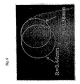
- the minimum radius of curvature of a former top of a former is defined as the minimum of the slice-minimum curvatures measured for the former top, each of which was measured from each wax slice as shown in Fig. 6.
- a slice-maximum curvature is also determined for each slice in a similar manner. Measured values larger than 5 mm were ignored. The maximum radius of curvature of a former is defined as the maximum of the measured slice-maximum curvatures.
- a projection having a height of about 33 ⁇ m is shown in Fig. 7A, but there is no high projection in this scanning.
- a projection having a height of about 87 ⁇ m is shown in Fig. 7B, and this is one of the high projections because it is taller than the average surface roughness by more than five times.
- the gas barrier film used in this embodiment has a laminate structure of a first polymer layer / gas barrier layer/ second polymer layer / third polymer layer, as shown in Fig. 4.
- the first and third polymer layers are made of a biaxially oriented polypropylene (OPP) film having an elastic modulus of 330,000 psi in the film feeding direction and having a thickness of about 15.2 ⁇ m.
- the second polymer layer is made of a polyethylene resin having a thickness of about 10.2 ⁇ m.
- OPP biaxially oriented polypropylene
- the second polymer layer is made of a polyethylene resin having a thickness of about 10.2 ⁇ m.
- the laminated films will bend when passing over the former top.
- a critical radius (Ry) of curvature at which the innermost portion of the outer layer immediately adjacent to the barrier layers reaches its elastic limit distortion in the film feeding direction, and then set the minimum value of the radius of curvature of the former top, which is responsible for the barrier property deterioration, to be equal to or higher than Ry.
- the value of Ry can be calculated using a numerical value analyzing method such as the finite element method.
- the finite element method as a numerical value analyzing method, and have divided into a plurality of fine elements a flat film at a stress-free state before receiving a bending deformation.
- the surface of the former in contact with the film is taken as a rigid (non-deformable) surface.
- elements used in finite element method analysis including a laminated shell element, a two-dimensional solid element and a three-dimensional solid element.
- 2-dimensional solid elements to divide the cross section of the films passing through the central portion of the former.
- the elements are generated so that each film has at least two elements in the film thickness direction, while an element aspect ratio in the film feeding direction is 20 or lower, and an aspect ratio of an area receiving a bending deformation at the former top is 4 or lower.
- the material characteristics used with the elements include an elastic modulus, an elastic limit distortion and a process curing coefficient (using the methods which will be described in detail later), which are obtained using constitution equations of elasto-plastic materials, based on the results of a uni-axial tension test conducted in the longitudinal direction on the test pieces, which are cut out into a plurality of short strips from each single layer forming the laminated films.
- the longitudinal direction is the film feeding direction.
- a force corresponding to a tensile stress applied to the films during the bag manufacturing process is included in the model as an external force.
- the Ry is determined, based on a repetitive calculation method, so that the external force matches the reaction force generated due to element deformation.
- a Tensilon tension testing device was employed.
- the film feeding direction is used as its longitudinal direction and, a force acting on the films which have been cut into short strips each having a width of 10 mm is converted into an electric output signal by a load cell with a strain gauge, thereby obtaining a relationship between a distortion and a force acting on the film pieces at room temperature.
- the elastic modulus is measured off the inclination in the stress-distortion graph thus provided.
- the method for obtaining a material constant from the results of the uni-axial tension test should not be limited to the method description above. Any method may be used if one uses a stress-distortion graph representing the results of the test, such that a slope of a straight line connecting a distortion point of 0.5% with another distortion point of 1.5% is defined as an elastic modulus, while a slope of a straight line connecting a distortion point of 7% with another distortion point of 12% is defined as a process curing coefficient, with an intersection of the two straight lines being an elastic limit distortion.
- the distortion of films receiving a bending deformation varies in the film thickness direction, i.e., changing from a tensile strain in the outside portion of the film to a compressive strain on the inside portion of the film.
- the elastic modulus of outer film 31 is equal to the elastic modulus of inner film 35, and when they are laminated in a symmetrical manner, a central axis 33 without any distortion is located at a central position in the film thickness direction.
- the thickness of the barrier layers is assumed to be sufficiently thin and their elastic moduli are assumed to be sufficiently small.
- the friction resistance on the inner surface is neglected.
- the strain represented by reference numeral 38 occurs in the innermost portion of the outer layer immediately adjacent to the barrier layer.
- the barrier layer should be designed to be disposed in the film so that the distortion is equal to or lower than the elastic limit distortion. This leads to reduced crack formation and, thus, improved barrier property.
- the rigidity of the outer film 41 when the rigidity of the outer film 41 is higher than that of the inner film 43, the center axis 42 moves in the film thickness direction toward the surface side (as shown in Fig. 6), thereby alleviating the distortion 46 of the barrier layers 45.
- the rigidity of the outer film is set to be higher than that of the inner film, such that when the film is bent over a curvature which is equal to the minimum radius at the former top, the distortion of the outer layer immediately adjacent to the barrier layers is equal to or lower than the elastic limit distortion.
- an elongation modifying agent such as petroleum resin is added to a homopolypropylene resin, thereby greatly increasing longitudinal elongation magnification in the film longitudinal direction (U. S. Patent 5,667,902).
- a homopolypropylene resin having a high crystalinity U. S. Patent application No. 60/357,837).
- a simultaneous biaxial orienting technique U. S. Patent application No. 09/921322.
- the first polymer layer is a polypropylene film
- the gas barrier film is an aluminum-coated film
- the second polymer layer is a polyethylene film
- the third polymer layer is a polypropylene.
- the first polymer layer or the third polymer layer is not necessarily of a single layer structure, but may be of a multiple layer structure including a skin layer, which can be formed by coating or simultaneously extruding the laminated layers.
- Fig. 10 shows a region represented by formula 1 as a function of a ratio of the elastic modulus and a ratio of the thickness. In this calculation, the thickness of the second polymer layer is 0.014 mm.
- the ratio of the elastic modulus of one polypropylene film (serving as the third polymer layer) in the film feeding direction to that of another polypropylene film (serving as the first polymer layer) was 1.3, the thickness ratio was 2.0, and the thickness of polyethylene laminated layers was 0.014 mm.
- the films used in this embodiment may include a third polymer layer which is a commonly used biaxially oriented polypropylene film having an elastic modulus of 330,000 psi and a thickness of 12.7 ⁇ m, and a first polymer layer which is a different polypropylene film whose rigidity in its longitudinal direction was improved in a biaxial orientation apparatus, having an elastic modulus of 432,000 psi and a thickness of 25.4 ⁇ m.
- a third polymer layer which is a commonly used biaxially oriented polypropylene film having an elastic modulus of 330,000 psi and a thickness of 12.7 ⁇ m
- a first polymer layer which is a different polypropylene film whose rigidity in its longitudinal direction was improved in a biaxial orientation apparatus, having an elastic modulus of 432,000 psi and a thickness of 25.4 ⁇ m.
Landscapes
- Engineering & Computer Science (AREA)
- Mechanical Engineering (AREA)
- Laminated Bodies (AREA)
- Bag Frames (AREA)
- Making Paper Articles (AREA)
- Containers And Plastic Fillers For Packaging (AREA)
Applications Claiming Priority (2)
| Application Number | Priority Date | Filing Date | Title |
|---|---|---|---|
| US382434 | 1999-08-25 | ||
| US10/382,434 US6811530B2 (en) | 2003-03-06 | 2003-03-06 | Bag manufacturing former laminated films |
Publications (3)
| Publication Number | Publication Date |
|---|---|
| EP1454735A2 true EP1454735A2 (de) | 2004-09-08 |
| EP1454735A3 EP1454735A3 (de) | 2004-11-03 |
| EP1454735B1 EP1454735B1 (de) | 2008-09-24 |
Family
ID=32824781
Family Applications (1)
| Application Number | Title | Priority Date | Filing Date |
|---|---|---|---|
| EP04251270A Expired - Lifetime EP1454735B1 (de) | 2003-03-06 | 2004-03-04 | Vorrichtung zur Herstellung von Beuteln und Verbundfolie |
Country Status (4)
| Country | Link |
|---|---|
| US (1) | US6811530B2 (de) |
| EP (1) | EP1454735B1 (de) |
| AT (1) | ATE409108T1 (de) |
| DE (1) | DE602004016701D1 (de) |
Cited By (2)
| Publication number | Priority date | Publication date | Assignee | Title |
|---|---|---|---|---|
| GB2489111B (en) * | 2011-03-17 | 2017-02-22 | Tna Australia Pty Ltd | A packaging machine former |
| CN109689331A (zh) * | 2016-11-17 | 2019-04-26 | 东洋制罐株式会社 | 层叠薄膜的立体成形方法 |
Families Citing this family (5)
| Publication number | Priority date | Publication date | Assignee | Title |
|---|---|---|---|---|
| US7003929B2 (en) * | 2003-07-25 | 2006-02-28 | Kraft Foods Holdings, Inc. | Apparatus and method for automated forming of sleeves for sliced products |
| US8247051B2 (en) * | 2003-08-11 | 2012-08-21 | The Glidden Company | Curable polymeric water based coating compositions and resulting coatings with barrier properties for gases and laminate structures |
| DE102011003875A1 (de) * | 2011-02-09 | 2012-08-09 | Wacker Chemie Ag | Verfahren und Vorrichtung zum Dosieren und Verpacken von Polysiliciumbruchstücken sowie Dosier- und Verpackungseinheit |
| US10953619B1 (en) * | 2014-03-15 | 2021-03-23 | Terminella Engineering Corporation | Former with insert |
| IT202000005068A1 (it) * | 2020-03-10 | 2021-09-10 | Gimsa S R L | Assieme formatore per macchine confezionatrici |
Family Cites Families (11)
| Publication number | Priority date | Publication date | Assignee | Title |
|---|---|---|---|---|
| US3042103A (en) * | 1958-09-30 | 1962-07-03 | Continental Can Co | Plastic film tube former |
| CH397517A (de) * | 1962-01-31 | 1965-08-15 | Hamac Hansella Aktiengesellsch | Vorrichtung zum Umformen eines Bandes aus Papier oder Kunststoff zu einem Schlauch |
| US3486424A (en) * | 1967-06-23 | 1969-12-30 | Woodman Co | Web former with wear insert |
| US3494265A (en) * | 1968-02-01 | 1970-02-10 | Woodman Co | Package former with multiple elliptical curve |
| US3636826A (en) * | 1969-10-24 | 1972-01-25 | Burlie R Bowen | Folding shoe for use in a packaging machine |
| US4532754A (en) * | 1983-04-20 | 1985-08-06 | Formers Of Houston, Inc. | Tube former apparatus |
| US4950345A (en) * | 1987-12-07 | 1990-08-21 | Frito-Lay, Inc. | Method and apparatus for making improved seals between polymeric film materials |
| DE4320713A1 (de) * | 1993-06-23 | 1995-01-05 | Rampf Giessharzsysteme Gmbh | Formschulter zur Herstellung und Befüllung von Schlauchgürteln |
| DE19539830A1 (de) * | 1995-10-26 | 1997-04-30 | Rovema Gmbh | Formschulter zur Umformung einer ebenen Folienbahn |
| JP3713108B2 (ja) * | 1996-08-14 | 2005-11-02 | 富士写真フイルム株式会社 | ピロータイプ包装装置 |
| US6589147B2 (en) * | 2001-09-08 | 2003-07-08 | J & F Business, Inc. | Lightweight former and former assembly |
-
2003
- 2003-03-06 US US10/382,434 patent/US6811530B2/en not_active Expired - Lifetime
-
2004
- 2004-03-04 DE DE602004016701T patent/DE602004016701D1/de not_active Expired - Lifetime
- 2004-03-04 AT AT04251270T patent/ATE409108T1/de not_active IP Right Cessation
- 2004-03-04 EP EP04251270A patent/EP1454735B1/de not_active Expired - Lifetime
Cited By (4)
| Publication number | Priority date | Publication date | Assignee | Title |
|---|---|---|---|---|
| GB2489111B (en) * | 2011-03-17 | 2017-02-22 | Tna Australia Pty Ltd | A packaging machine former |
| US9598189B2 (en) | 2011-03-17 | 2017-03-21 | Tna Australia Pty Limited | Packaging machine former |
| CN109689331A (zh) * | 2016-11-17 | 2019-04-26 | 东洋制罐株式会社 | 层叠薄膜的立体成形方法 |
| CN109689331B (zh) * | 2016-11-17 | 2020-12-11 | 东洋制罐株式会社 | 层叠薄膜的立体成形方法 |
Also Published As
| Publication number | Publication date |
|---|---|
| US20040176230A1 (en) | 2004-09-09 |
| ATE409108T1 (de) | 2008-10-15 |
| EP1454735A3 (de) | 2004-11-03 |
| US6811530B2 (en) | 2004-11-02 |
| EP1454735B1 (de) | 2008-09-24 |
| DE602004016701D1 (de) | 2008-11-06 |
Similar Documents
| Publication | Publication Date | Title |
|---|---|---|
| EP1879056B1 (de) | Schaum-blatt für einen reflektor, prozess zur herstellung des blatts und zur herstellung eines reflektors | |
| EP0743902B1 (de) | Mehrschnittfolie aus ethylencopolymer | |
| US4062712A (en) | Method for making a packing laminate | |
| US6811530B2 (en) | Bag manufacturing former laminated films | |
| EP0640461A1 (de) | Verfahren zur Herstellung eines flexibelen Verpackungsmaterials mit Nuten | |
| CA2129970A1 (en) | Polypropylene laminates and process for the production thereof | |
| EP4098686A1 (de) | Harzschaumkörper auf polypropylenbasis, schaumteilchen auf polypropylenbasis und verfahren zu seiner herstellung | |
| CN1151920C (zh) | 呈现改进热封特性的定向薄膜的交叉层合物及该交叉层合物的制造方法 | |
| US6132539A (en) | Method for manufacturing packaging materials with a polyolefin foam layer | |
| US5318824A (en) | Packaging structure | |
| US4460631A (en) | Sealable, biaxially stretched polypropylene film having high scratch resistance, and process for its manufacture | |
| RU2211107C2 (ru) | Способ получения консервных банок посредством утонения стенок | |
| EP3858183B1 (de) | Reissverschlussband und mit einem reissverschluss versehener behälter | |
| JP4411960B2 (ja) | ポリプロピレン系多層シーラントフィルム、およびそのシーラントフィルムを用いたラミネートフィルム | |
| JP5009768B2 (ja) | ポリプロピレン系積層フィルム及びそれを用いた包装体 | |
| EP0245034B1 (de) | Packungsstruktur und Verfahren zu dessen Herstellung | |
| WO2005090073A1 (ja) | ポリプロピレン系積層フィルム及びそれを用いた包装体 | |
| US11097880B2 (en) | Packaging container | |
| EP3769937A1 (de) | Verfahren zur bereitstellung eines basisprodukts und eines mit einem langen körper bedeckten dorns | |
| JP3675904B2 (ja) | 薄膜ガスバリア性フィルム | |
| EP4501637A1 (de) | Coextrudierte folie | |
| JP2005297544A (ja) | ポリプロピレン系積層フィルム及びそれを用いた包装体 | |
| WO1991016199A1 (en) | Free edge-sealed film articles and process of making same | |
| KR102310570B1 (ko) | 다층 구조의 pe 포대 제작용 필름 제조방법 | |
| WO1983002747A1 (en) | Thermoforming coextruded plastic sheets |
Legal Events
| Date | Code | Title | Description |
|---|---|---|---|
| PUAI | Public reference made under article 153(3) epc to a published international application that has entered the european phase |
Free format text: ORIGINAL CODE: 0009012 |
|
| 17P | Request for examination filed |
Effective date: 20040325 |
|
| AK | Designated contracting states |
Kind code of ref document: A2 Designated state(s): AT BE BG CH CY CZ DE DK EE ES FI FR GB GR HU IE IT LI LU MC NL PL PT RO SE SI SK TR |
|
| AX | Request for extension of the european patent |
Extension state: AL HR LT LV MK |
|
| PUAL | Search report despatched |
Free format text: ORIGINAL CODE: 0009013 |
|
| AK | Designated contracting states |
Kind code of ref document: A3 Designated state(s): AT BE BG CH CY CZ DE DK EE ES FI FR GB GR HU IE IT LI LU MC NL PL PT RO SE SI SK TR |
|
| AX | Request for extension of the european patent |
Extension state: AL HR LT LV MK |
|
| AKX | Designation fees paid |
Designated state(s): AT BE BG CH CY CZ DE DK EE ES FI FR GB GR HU IE IT LI LU MC NL PL PT RO SE SI SK TR |
|
| 17Q | First examination report despatched |
Effective date: 20051130 |
|
| GRAP | Despatch of communication of intention to grant a patent |
Free format text: ORIGINAL CODE: EPIDOSNIGR1 |
|
| GRAS | Grant fee paid |
Free format text: ORIGINAL CODE: EPIDOSNIGR3 |
|
| GRAA | (expected) grant |
Free format text: ORIGINAL CODE: 0009210 |
|
| AK | Designated contracting states |
Kind code of ref document: B1 Designated state(s): AT BE BG CH CY CZ DE DK EE ES FI FR GB GR HU IE IT LI LU MC NL PL PT RO SE SI SK TR |
|
| REG | Reference to a national code |
Ref country code: GB Ref legal event code: FG4D |
|
| REG | Reference to a national code |
Ref country code: CH Ref legal event code: EP |
|
| REG | Reference to a national code |
Ref country code: IE Ref legal event code: FG4D |
|
| REF | Corresponds to: |
Ref document number: 602004016701 Country of ref document: DE Date of ref document: 20081106 Kind code of ref document: P |
|
| PG25 | Lapsed in a contracting state [announced via postgrant information from national office to epo] |
Ref country code: SI Free format text: LAPSE BECAUSE OF FAILURE TO SUBMIT A TRANSLATION OF THE DESCRIPTION OR TO PAY THE FEE WITHIN THE PRESCRIBED TIME-LIMIT Effective date: 20080924 Ref country code: FI Free format text: LAPSE BECAUSE OF FAILURE TO SUBMIT A TRANSLATION OF THE DESCRIPTION OR TO PAY THE FEE WITHIN THE PRESCRIBED TIME-LIMIT Effective date: 20080924 Ref country code: AT Free format text: LAPSE BECAUSE OF FAILURE TO SUBMIT A TRANSLATION OF THE DESCRIPTION OR TO PAY THE FEE WITHIN THE PRESCRIBED TIME-LIMIT Effective date: 20080924 |
|
| PG25 | Lapsed in a contracting state [announced via postgrant information from national office to epo] |
Ref country code: BG Free format text: LAPSE BECAUSE OF FAILURE TO SUBMIT A TRANSLATION OF THE DESCRIPTION OR TO PAY THE FEE WITHIN THE PRESCRIBED TIME-LIMIT Effective date: 20081224 Ref country code: ES Free format text: LAPSE BECAUSE OF FAILURE TO SUBMIT A TRANSLATION OF THE DESCRIPTION OR TO PAY THE FEE WITHIN THE PRESCRIBED TIME-LIMIT Effective date: 20090104 |
|
| PG25 | Lapsed in a contracting state [announced via postgrant information from national office to epo] |
Ref country code: PT Free format text: LAPSE BECAUSE OF FAILURE TO SUBMIT A TRANSLATION OF THE DESCRIPTION OR TO PAY THE FEE WITHIN THE PRESCRIBED TIME-LIMIT Effective date: 20090224 Ref country code: CZ Free format text: LAPSE BECAUSE OF FAILURE TO SUBMIT A TRANSLATION OF THE DESCRIPTION OR TO PAY THE FEE WITHIN THE PRESCRIBED TIME-LIMIT Effective date: 20080924 Ref country code: SK Free format text: LAPSE BECAUSE OF FAILURE TO SUBMIT A TRANSLATION OF THE DESCRIPTION OR TO PAY THE FEE WITHIN THE PRESCRIBED TIME-LIMIT Effective date: 20080924 Ref country code: RO Free format text: LAPSE BECAUSE OF FAILURE TO SUBMIT A TRANSLATION OF THE DESCRIPTION OR TO PAY THE FEE WITHIN THE PRESCRIBED TIME-LIMIT Effective date: 20080924 |
|
| PG25 | Lapsed in a contracting state [announced via postgrant information from national office to epo] |
Ref country code: DK Free format text: LAPSE BECAUSE OF FAILURE TO SUBMIT A TRANSLATION OF THE DESCRIPTION OR TO PAY THE FEE WITHIN THE PRESCRIBED TIME-LIMIT Effective date: 20080924 Ref country code: EE Free format text: LAPSE BECAUSE OF FAILURE TO SUBMIT A TRANSLATION OF THE DESCRIPTION OR TO PAY THE FEE WITHIN THE PRESCRIBED TIME-LIMIT Effective date: 20080924 |
|
| PLBE | No opposition filed within time limit |
Free format text: ORIGINAL CODE: 0009261 |
|
| STAA | Information on the status of an ep patent application or granted ep patent |
Free format text: STATUS: NO OPPOSITION FILED WITHIN TIME LIMIT |
|
| 26N | No opposition filed |
Effective date: 20090625 |
|
| PG25 | Lapsed in a contracting state [announced via postgrant information from national office to epo] |
Ref country code: MC Free format text: LAPSE BECAUSE OF NON-PAYMENT OF DUE FEES Effective date: 20090331 |
|
| REG | Reference to a national code |
Ref country code: CH Ref legal event code: PL |
|
| REG | Reference to a national code |
Ref country code: FR Ref legal event code: ST Effective date: 20091130 |
|
| REG | Reference to a national code |
Ref country code: IE Ref legal event code: MM4A |
|
| PG25 | Lapsed in a contracting state [announced via postgrant information from national office to epo] |
Ref country code: LI Free format text: LAPSE BECAUSE OF NON-PAYMENT OF DUE FEES Effective date: 20090331 Ref country code: SE Free format text: LAPSE BECAUSE OF FAILURE TO SUBMIT A TRANSLATION OF THE DESCRIPTION OR TO PAY THE FEE WITHIN THE PRESCRIBED TIME-LIMIT Effective date: 20081224 Ref country code: CH Free format text: LAPSE BECAUSE OF NON-PAYMENT OF DUE FEES Effective date: 20090331 Ref country code: IE Free format text: LAPSE BECAUSE OF NON-PAYMENT OF DUE FEES Effective date: 20090304 |
|
| PG25 | Lapsed in a contracting state [announced via postgrant information from national office to epo] |
Ref country code: FR Free format text: LAPSE BECAUSE OF NON-PAYMENT OF DUE FEES Effective date: 20091123 |
|
| PG25 | Lapsed in a contracting state [announced via postgrant information from national office to epo] |
Ref country code: PL Free format text: LAPSE BECAUSE OF FAILURE TO SUBMIT A TRANSLATION OF THE DESCRIPTION OR TO PAY THE FEE WITHIN THE PRESCRIBED TIME-LIMIT Effective date: 20080924 |
|
| PG25 | Lapsed in a contracting state [announced via postgrant information from national office to epo] |
Ref country code: GR Free format text: LAPSE BECAUSE OF FAILURE TO SUBMIT A TRANSLATION OF THE DESCRIPTION OR TO PAY THE FEE WITHIN THE PRESCRIBED TIME-LIMIT Effective date: 20081225 |
|
| PG25 | Lapsed in a contracting state [announced via postgrant information from national office to epo] |
Ref country code: LU Free format text: LAPSE BECAUSE OF NON-PAYMENT OF DUE FEES Effective date: 20090304 |
|
| PG25 | Lapsed in a contracting state [announced via postgrant information from national office to epo] |
Ref country code: HU Free format text: LAPSE BECAUSE OF FAILURE TO SUBMIT A TRANSLATION OF THE DESCRIPTION OR TO PAY THE FEE WITHIN THE PRESCRIBED TIME-LIMIT Effective date: 20090325 |
|
| PG25 | Lapsed in a contracting state [announced via postgrant information from national office to epo] |
Ref country code: TR Free format text: LAPSE BECAUSE OF FAILURE TO SUBMIT A TRANSLATION OF THE DESCRIPTION OR TO PAY THE FEE WITHIN THE PRESCRIBED TIME-LIMIT Effective date: 20080924 |
|
| PG25 | Lapsed in a contracting state [announced via postgrant information from national office to epo] |
Ref country code: CY Free format text: LAPSE BECAUSE OF FAILURE TO SUBMIT A TRANSLATION OF THE DESCRIPTION OR TO PAY THE FEE WITHIN THE PRESCRIBED TIME-LIMIT Effective date: 20080924 |
|
| PGFP | Annual fee paid to national office [announced via postgrant information from national office to epo] |
Ref country code: NL Payment date: 20160310 Year of fee payment: 13 |
|
| PGFP | Annual fee paid to national office [announced via postgrant information from national office to epo] |
Ref country code: BE Payment date: 20151223 Year of fee payment: 13 |
|
| PGFP | Annual fee paid to national office [announced via postgrant information from national office to epo] |
Ref country code: IT Payment date: 20160324 Year of fee payment: 13 |
|
| REG | Reference to a national code |
Ref country code: NL Ref legal event code: MM Effective date: 20170401 |
|
| PG25 | Lapsed in a contracting state [announced via postgrant information from national office to epo] |
Ref country code: NL Free format text: LAPSE BECAUSE OF NON-PAYMENT OF DUE FEES Effective date: 20170401 |
|
| PG25 | Lapsed in a contracting state [announced via postgrant information from national office to epo] |
Ref country code: IT Free format text: LAPSE BECAUSE OF NON-PAYMENT OF DUE FEES Effective date: 20170304 |
|
| REG | Reference to a national code |
Ref country code: BE Ref legal event code: MM Effective date: 20170331 |
|
| PG25 | Lapsed in a contracting state [announced via postgrant information from national office to epo] |
Ref country code: BE Free format text: LAPSE BECAUSE OF NON-PAYMENT OF DUE FEES Effective date: 20170331 |
|
| PGFP | Annual fee paid to national office [announced via postgrant information from national office to epo] |
Ref country code: GB Payment date: 20220321 Year of fee payment: 19 Ref country code: DE Payment date: 20220322 Year of fee payment: 19 |
|
| REG | Reference to a national code |
Ref country code: DE Ref legal event code: R119 Ref document number: 602004016701 Country of ref document: DE |
|
| GBPC | Gb: european patent ceased through non-payment of renewal fee |
Effective date: 20230304 |
|
| PG25 | Lapsed in a contracting state [announced via postgrant information from national office to epo] |
Ref country code: GB Free format text: LAPSE BECAUSE OF NON-PAYMENT OF DUE FEES Effective date: 20230304 |
|
| PG25 | Lapsed in a contracting state [announced via postgrant information from national office to epo] |
Ref country code: GB Free format text: LAPSE BECAUSE OF NON-PAYMENT OF DUE FEES Effective date: 20230304 Ref country code: DE Free format text: LAPSE BECAUSE OF NON-PAYMENT OF DUE FEES Effective date: 20231003 |