EP1454764B1 - Vorderradträger für einen Rollstuhl - Google Patents
Vorderradträger für einen Rollstuhl Download PDFInfo
- Publication number
- EP1454764B1 EP1454764B1 EP03004757A EP03004757A EP1454764B1 EP 1454764 B1 EP1454764 B1 EP 1454764B1 EP 03004757 A EP03004757 A EP 03004757A EP 03004757 A EP03004757 A EP 03004757A EP 1454764 B1 EP1454764 B1 EP 1454764B1
- Authority
- EP
- European Patent Office
- Prior art keywords
- curved
- front wheel
- wheel support
- curved tube
- curved part
- Prior art date
- Legal status (The legal status is an assumption and is not a legal conclusion. Google has not performed a legal analysis and makes no representation as to the accuracy of the status listed.)
- Expired - Lifetime
Links
Images




Classifications
-
- B—PERFORMING OPERATIONS; TRANSPORTING
- B60—VEHICLES IN GENERAL
- B60B—VEHICLE WHEELS; CASTORS; AXLES FOR WHEELS OR CASTORS; INCREASING WHEEL ADHESION
- B60B33/00—Castors in general ; Anti-clogging castors
- B60B33/0047—Castors in general ; Anti-clogging castors characterised by details of the rolling axle
- B60B33/0052—Castors in general ; Anti-clogging castors characterised by details of the rolling axle the rolling axle being inclined
-
- A—HUMAN NECESSITIES
- A61—MEDICAL OR VETERINARY SCIENCE; HYGIENE
- A61G—TRANSPORT, PERSONAL CONVEYANCES, OR ACCOMMODATION SPECIALLY ADAPTED FOR PATIENTS OR DISABLED PERSONS; OPERATING TABLES OR CHAIRS; CHAIRS FOR DENTISTRY; FUNERAL DEVICES
- A61G5/00—Chairs or personal conveyances specially adapted for patients or disabled persons, e.g. wheelchairs
- A61G5/10—Parts, details or accessories
-
- B—PERFORMING OPERATIONS; TRANSPORTING
- B60—VEHICLES IN GENERAL
- B60B—VEHICLE WHEELS; CASTORS; AXLES FOR WHEELS OR CASTORS; INCREASING WHEEL ADHESION
- B60B33/00—Castors in general ; Anti-clogging castors
- B60B33/0002—Castors in general ; Anti-clogging castors assembling to the object, e.g. furniture
-
- B—PERFORMING OPERATIONS; TRANSPORTING
- B60—VEHICLES IN GENERAL
- B60B—VEHICLE WHEELS; CASTORS; AXLES FOR WHEELS OR CASTORS; INCREASING WHEEL ADHESION
- B60B33/00—Castors in general ; Anti-clogging castors
- B60B33/04—Castors in general ; Anti-clogging castors adjustable, e.g. in height; linearly shifting castors
-
- Y—GENERAL TAGGING OF NEW TECHNOLOGICAL DEVELOPMENTS; GENERAL TAGGING OF CROSS-SECTIONAL TECHNOLOGIES SPANNING OVER SEVERAL SECTIONS OF THE IPC; TECHNICAL SUBJECTS COVERED BY FORMER USPC CROSS-REFERENCE ART COLLECTIONS [XRACs] AND DIGESTS
- Y10—TECHNICAL SUBJECTS COVERED BY FORMER USPC
- Y10T—TECHNICAL SUBJECTS COVERED BY FORMER US CLASSIFICATION
- Y10T403/00—Joints and connections
- Y10T403/32—Articulated members
- Y10T403/32254—Lockable at fixed position
- Y10T403/32467—Telescoping members
-
- Y—GENERAL TAGGING OF NEW TECHNOLOGICAL DEVELOPMENTS; GENERAL TAGGING OF CROSS-SECTIONAL TECHNOLOGIES SPANNING OVER SEVERAL SECTIONS OF THE IPC; TECHNICAL SUBJECTS COVERED BY FORMER USPC CROSS-REFERENCE ART COLLECTIONS [XRACs] AND DIGESTS
- Y10—TECHNICAL SUBJECTS COVERED BY FORMER USPC
- Y10T—TECHNICAL SUBJECTS COVERED BY FORMER US CLASSIFICATION
- Y10T403/00—Joints and connections
- Y10T403/32—Articulated members
- Y10T403/32254—Lockable at fixed position
- Y10T403/32467—Telescoping members
- Y10T403/32475—Telescoping members having detent
- Y10T403/32501—Cam or wedge
-
- Y—GENERAL TAGGING OF NEW TECHNOLOGICAL DEVELOPMENTS; GENERAL TAGGING OF CROSS-SECTIONAL TECHNOLOGIES SPANNING OVER SEVERAL SECTIONS OF THE IPC; TECHNICAL SUBJECTS COVERED BY FORMER USPC CROSS-REFERENCE ART COLLECTIONS [XRACs] AND DIGESTS
- Y10—TECHNICAL SUBJECTS COVERED BY FORMER USPC
- Y10T—TECHNICAL SUBJECTS COVERED BY FORMER US CLASSIFICATION
- Y10T403/00—Joints and connections
- Y10T403/32—Articulated members
- Y10T403/32254—Lockable at fixed position
- Y10T403/32467—Telescoping members
- Y10T403/32524—Self-locking
Definitions
- the present invention relates to a front-wheel support for a wheel chair in accordance with claim 1 to 6, and wheel chair comprising such a front-wheel support, in accordance with claim 7.
- Wheel chairs typically have one or two front wheels. These front wheels are fixed to the frame of the wheel chair by means of a front wheel support.
- the front wheel support is usually designed to be operated in a upright position where the front wheel fork turns about an axis that is essentially vertical with respect to the ground.
- Document DE 39 04 150 discloses an example of such a front wheel support.
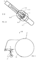
- a first embodiment, according to the present invention, is depicted in Figs. 1A 1B , and 1C .
- the front wheel support 10 for a wheel chair is depicted. Only part of a frame member 9 of the wheel chair is visible.
- the front wheel support 10 comprises a first curved part in form of a curved tube 11 being attached to the frame member 9 of the wheel chair.
- the first curved tube 11 is attached to the frame member 9 by means of welding.
- the first curved tube 11 may also be an integral part of the frame member 9 .
- a second curved part 12, which may be a tube part or a massive part, is provided.
- the curved tube 11 and the curved part 12 can be bended in the direction as depicted or in another direction.
- This second curved part 12 has a first portion 12.1 with a curvature being identical to the curvature of the first curved tube 11. Furthermore, the first portion 12.1 has a cross section A1 allowing the first portion 12.1 to fit inside the first curved tube 11, as illustrated in Fig. 1B .
- the second curved part 12 comprises a second portion 12.2 with a wheel fork seat for mounting a front wheel fork of said wheel chair. The front wheel fork and the front wheel are not visible in Figs. 1A, 1B , and 1C .
- the front wheel support 10 illustrated in the Figs. 1A, 1B , and 1C comprises a section that can be extended or expanded when being situated inside the first curved tube 11 in order to form a tight fit with respect to the second curved part 12. For this reason, the first portion 12.1 has a fork-like shape with two ends 12.3 .
- the load path is provided between the first portion 12.1 of the second curved part 12 and the first curved tube 11 if the screw 15 is in the right position.
- the securing arrangement 14 can be released by turning the screw 15 in the opposite direction.
- the two ends 12.3 will return to their original position since the conical part withdraws.
- FIG. 2 A schematic representation of a wheel chair 20 is given in Fig. 2 .
- the wheel chair 20 comprises at least one front wheel support 10 , according to the present invention.
- This front wheel support 10 comprises a first curved tube 11 being attached to the frame member 9 of the wheel chair.
- the first curved tube 11 is attached to the frame member 9 .
- the first curved tube 11 may be an integral part of the frame member 9 , as illustrated in Fig. 2 .
- a second curved part 12 is provided.
- This second curved part 12 has a first portion 12.1 with a curvature being identical to the curvature of the first curved tube 11 .
- the second curved part 12 comprises a second portion with a wheel fork 13 for mounting a front wheel 21 of said wheel chair 20.
- the wheel chair 20 further comprises a rear wheel 22.
- Figs. 3A through 3C Further details of the embodiment of Figs. 1A through 1C are depicted in Figs. 3A through 3C .
- a special securing arrangement 14 is provided.
- the front wheel support 10 illustrated in the Figs. 3A , 3B , and 3C comprises a section that can be extended or expanded when being situated inside the first curved tube 11 in order to form a tight fit with respect to the second curved part 12 .
- the first portion 12.1 has a fork-like shape with two ends 12.3. These two ends 12.3 are spaced apart so that a screw 15 together with a conical element 16 fits between the two ends 12.3 , as illustrated in Fig. 1C and 3C .
- the conical part 16 When turning the screw 15 , the conical part 16 is pushed between the two ends 12.3 of the first portion 12.1 . Due to this, the two ends 12.3 are pushed against the inner wall of the first curved tube 11. The load path is provided between the first portion 12.1 of the second curved part 12 and the first curved tube 11 if the screw 15 (not visible in any of the Figs 3A through 3C ) is in the right position.
- the securing arrangement 14 can be released by turning the screw 15 in the opposite direction.
- the two ends 12.3 will return to their original position since the conical part 16 withdraws.
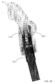
- FIG. 4A and 4B Yet another embodiment is depicted in Figs. 4A and 4B .
- the first curved tube 11 is attached to the frame 9.
- the second curved part 12 comprises a longitudinal slit 12.4 .
- the securing arrangement 14 comprises a sliding element 14.1 with a threaded hole 14.2 and a screw. This screw is not visible in the Figs. 4A and 4B .
- the screw sits in a mounting piece 14.4 that is attached to the outside of the first curved tube 11.
- the screw is inserted through a hole 14.5 in the mounting piece 14.4 and sits in the threaded hole 14.2 of the sliding element 14.1. and the screw is accessible from outside through the longitudinal slit 12.4.
- the sliding element 14.1 moves together with the first portion 12.1 inside the first curved tube 11 up or down, if the second curved part 12 is pushed into or pulled out of the first curved tube 11 .
- the screw is tightend. Due to this, the sliding element 14.1 together with the second curved part 12 is fixed with respect to the first curved tube 11 and the mounting piece 14.4.
- Figs. 4A and 4B also show that the second curved part 12 comprises a second portion 12.2 with a wheel fork seat 13.1 for mounting a front wheel fork 13 of said wheel chair.
- the first curved tube 11 comprises a securing arrangement 14 with a nut 17 .
- This nut 17 sits on the end portion 11. 1 of the first curved tube 11 .
- the end portion of the first curved tube 11 is threaded allowing the nut 17 to be fixed or released by turning it.
- Inside the first curved tube 11 there is a conical part.
- This conical part sits on the first portion 12.1 of the second curved part 12.
- the conical part provides for a tight fight between the end portion 11.1 of the first curved tube 11 and the first portion 12.1 of the second curved part 12 .
- the principle is similar to the one being used in connection with garden hoses or pipes where one cylindrical piece is to be tightly connected to another cylindrical piece in the same manner. The difference, however, is in the dimensions and materials used. Since the front wheel support 10 has to be stable, a more solid and rigid version is required.
Landscapes
- Engineering & Computer Science (AREA)
- Mechanical Engineering (AREA)
- Health & Medical Sciences (AREA)
- Life Sciences & Earth Sciences (AREA)
- Animal Behavior & Ethology (AREA)
- General Health & Medical Sciences (AREA)
- Public Health (AREA)
- Veterinary Medicine (AREA)
- Chair Legs, Seat Parts, And Backrests (AREA)
- Handcart (AREA)
Claims (7)
- Vorderradstütze (10) für einen Rollstuhl (20), wobei die Vorderradstütze (10) umfasst:- ein gekrümmtes Rohr (11), das an einem Rahmenelement (9) eines Rollstuhls (20) befestigbar ist, und- einen gekrümmten Teil (12), wobei der gekrümmte Teil (12) umfasst:wobei der erste Abschnitt (12.1) des gekrümmten Teils (12) teleskopisch in dem gekrümmten Rohr (11) schiebbar ist, wodurch eine größere oder kleinere Überlappung zwischen dem ersten Abschnitt (12.1) des gekrümmten Teils (12) und dem gekrümmten Rohr (11) geschaffen wird, und- einen ersten Abschnitt (12.1) mit- einer Krümmung, die identisch mit der Krümmung des ersten gekrümmten Rohres (11) ist, und- einem Querschnitt (A1), der es dem ersten Abschnitt (12.1) des gekrümmten Teils (12) ermöglicht, in das gekrümmte Rohr (11) eingepasst zu werden, und- einen zweiten Abschnitt (12.2) mit einer Radgabel (13), umfassend ein Vorderrad (21),
wobei eine Sicherungsanordnung (14) vorgesehen ist, die es dem gekrümmten Rohr (11) ermöglicht, in Bezug auf den gekrümmten Teil (12) fixiert zu werden,
dadurch gekennzeichnet, dass aufgrund der Krümmung des gekrümmten Rohrs und des ersten Abschnitts des gekrümmten Teils die Neigung des Vorderrades (21) einstellbar ist, indem die Überlappung vergrößert oder verkleinert wird. - Die Vorderradstütze (10) nach Anspruch 1, wobei ein Belastungsweg zwischen dem ersten Abschnitt (12.1) des gekrümmten Teils (12) und dem gekrümmten Rohr (11) vorgesehen ist.
- Die Vorderradstütze (10) nach Anspruch 1, wobei die Sicherungsanordnung (14) ein gleitendes Element (14.1) mit einem Gewindeloch (14.2), eine Schraube und einen Montageteil (14.4) umfasst.
- Die Vorderradstütze (10) nach Anspruch 1, wobei der erste Abschnitt (12.1) des gekrümmten Teils (12) einen Abschnitt (12.3) umfasst, der gedehnt oder erweitert werden kann, um einen Formschluss mit dem gekrümmten Teil (12) zu bilden.
- Die Vorderradstütze (10) nach Anspruch 4, wobei der Abschnitt (12.3) mittels einer Schraube (15) oder einer Mutter (17) gedehnt oder erweitert werden kann.
- Die Vorderradstütze (10) nach einem der Ansprüche 1 oder 2, wobei die Sicherungsanordnung (14) eine Mutter (17) und einen konischen Teil umfasst, der in dem gekrümmten Rohr (11) sitzt.
- Rollstuhl (20), umfassend mindestens eine Vorderradstütze (10) nach einem der vorhergehenden Ansprüche.
Priority Applications (3)
| Application Number | Priority Date | Filing Date | Title |
|---|---|---|---|
| DE60333540T DE60333540D1 (de) | 2003-03-04 | 2003-03-04 | Vorderradträger für einen Rollstuhl |
| EP03004757A EP1454764B1 (de) | 2003-03-04 | 2003-03-04 | Vorderradträger für einen Rollstuhl |
| US10/791,699 US7377713B2 (en) | 2003-03-04 | 2004-03-04 | Front-wheel support for a wheel chair |
Applications Claiming Priority (1)
| Application Number | Priority Date | Filing Date | Title |
|---|---|---|---|
| EP03004757A EP1454764B1 (de) | 2003-03-04 | 2003-03-04 | Vorderradträger für einen Rollstuhl |
Publications (2)
| Publication Number | Publication Date |
|---|---|
| EP1454764A1 EP1454764A1 (de) | 2004-09-08 |
| EP1454764B1 true EP1454764B1 (de) | 2010-07-28 |
Family
ID=32798767
Family Applications (1)
| Application Number | Title | Priority Date | Filing Date |
|---|---|---|---|
| EP03004757A Expired - Lifetime EP1454764B1 (de) | 2003-03-04 | 2003-03-04 | Vorderradträger für einen Rollstuhl |
Country Status (3)
| Country | Link |
|---|---|
| US (1) | US7377713B2 (de) |
| EP (1) | EP1454764B1 (de) |
| DE (1) | DE60333540D1 (de) |
Families Citing this family (4)
| Publication number | Priority date | Publication date | Assignee | Title |
|---|---|---|---|---|
| WO2010055372A1 (en) * | 2008-11-13 | 2010-05-20 | Sansegal China Hong Kong, Ltd. | Three-wheeled skateboard system and method |
| US9850968B2 (en) * | 2014-04-29 | 2017-12-26 | Goodrich Corporation | Torque bar and methods for making |
| EP3620146B1 (de) | 2018-09-06 | 2023-02-15 | Invacare International GmbH | Lenkradstützeinrichtung für einen rollstuhl und rollstuhl damit |
| CN111907983A (zh) * | 2020-09-14 | 2020-11-10 | 曾艳红 | 一种户外移动式防倾倒垃圾桶 |
Family Cites Families (30)
| Publication number | Priority date | Publication date | Assignee | Title |
|---|---|---|---|---|
| GB1053263A (de) * | 1900-01-01 | |||
| US102927A (en) * | 1870-05-10 | Improvement in children s carriages | ||
| US292873A (en) * | 1884-02-05 | Method of and machinery for treating rags for paper-stock | ||
| US554381A (en) * | 1896-02-11 | Stove-leg | ||
| US1482955A (en) * | 1921-12-10 | 1924-02-05 | United Electric Company | Adjustable caster |
| US1835144A (en) * | 1928-12-08 | 1931-12-08 | George A Cleaveland | Adjustable swivel caster |
| US2534539A (en) * | 1945-10-15 | 1950-12-19 | Oscar T Topper | Stroller |
| US2649611A (en) * | 1950-11-21 | 1953-08-25 | Chester W Muszynski | Coaster for furniture legs |
| ZA785309B (en) * | 1977-09-21 | 1979-08-29 | Lamondine Sa | Improvements in or relating to wheel support arrangements |
| US4265382A (en) * | 1979-10-12 | 1981-05-05 | Edwards Thomas M | Multi purpose carrier for vehicle |
| US4357735A (en) * | 1981-06-05 | 1982-11-09 | Graco Metal Products, Inc. | Ball and socket safety hinge |
| US4386466A (en) * | 1981-08-17 | 1983-06-07 | Dale L. Avers | Crutch gauge measuring device |
| US4813693A (en) * | 1986-09-30 | 1989-03-21 | Invacare Corporation | Adjustable child's wheelchair |
| GB8807142D0 (en) * | 1988-03-25 | 1988-04-27 | Goodall M J | Extendable seat arrangement for vehicles |
| DE3904150C1 (en) * | 1989-02-11 | 1990-07-05 | Kernforschungszentrum Karlsruhe Gmbh, 7500 Karlsruhe, De | Lightweight wheelchair |
| US5267946A (en) * | 1992-04-01 | 1993-12-07 | Samuel Singer | Knee brace with adjustable rigid posterior strut |
| US5149092A (en) * | 1991-08-16 | 1992-09-22 | Kevin Parsons | Locking means for extendable baton |
| US5373591A (en) * | 1992-09-02 | 1994-12-20 | Sari H. Gill | Shower-commode chair and transfer track |
| US5361454A (en) * | 1993-08-02 | 1994-11-08 | Century Products Company | Snap-on swivel wheel assembly |
| US5806548A (en) * | 1994-09-06 | 1998-09-15 | Goldstein; Jeffery P. | Quadcane with adjustable stance |
| US5800318A (en) * | 1995-03-20 | 1998-09-01 | Coviello; Gerald A. | Rehabilitation thru athletic training principal/walker type device |
| US5918553A (en) * | 1997-04-28 | 1999-07-06 | Teknion Furniture Systems | Adjustable height tables |
| DE19808300C2 (de) * | 1998-02-27 | 2000-06-08 | Bock Orthopaed Ind | Rollstuhl |
| US6085766A (en) * | 1998-09-25 | 2000-07-11 | Geary; John A. | Geary convertible crutch system |
| TW351303U (en) * | 1998-10-06 | 1999-01-21 | Link Treasure Ltd | Foldable baby stroller |
| DE29901471U1 (de) * | 1999-01-29 | 1999-07-22 | Sopur Medizintechnik GmbH, 69254 Malsch | Handbetätigbarer Rollstuhl |
| US6076205A (en) * | 1999-03-08 | 2000-06-20 | Yang; Chih-Huang | Playpen with detachable frame sections |
| US6674256B2 (en) * | 2000-06-21 | 2004-01-06 | Mobility E-Z, Llc | Battery powered, joystick controlled folding wheelchair |
| US6595530B2 (en) * | 2001-03-29 | 2003-07-22 | American Healthcare Solutions, Inc. | Medical walker |
| JP2006131198A (ja) * | 2004-10-04 | 2006-05-25 | Kazuyoshi Kazaoka | 車輪構造体及び車輪構造体を有する車輌 |
-
2003
- 2003-03-04 EP EP03004757A patent/EP1454764B1/de not_active Expired - Lifetime
- 2003-03-04 DE DE60333540T patent/DE60333540D1/de not_active Expired - Lifetime
-
2004
- 2004-03-04 US US10/791,699 patent/US7377713B2/en not_active Expired - Fee Related
Also Published As
| Publication number | Publication date |
|---|---|
| EP1454764A1 (de) | 2004-09-08 |
| US7377713B2 (en) | 2008-05-27 |
| DE60333540D1 (de) | 2010-09-09 |
| US20040172786A1 (en) | 2004-09-09 |
Similar Documents
| Publication | Publication Date | Title |
|---|---|---|
| US5163339A (en) | Bicycle auxiliary handle assembly | |
| EP2836374A1 (de) | Rollenmontageanordnung für einen rollstuhl | |
| US20200214439A1 (en) | Height adjustable table and components of same | |
| TWI775984B (zh) | 自行車座椅附接組件 | |
| US10238556B1 (en) | Multi-adjustable wheelchair and frame therefor | |
| US20210120953A1 (en) | Table glide spacer | |
| US7377713B2 (en) | Front-wheel support for a wheel chair | |
| GB2394505A (en) | A slidable and rotatable clamp arrangement for an angler's seat box | |
| EP2845786B1 (de) | Wandmontierter Fahrradträger | |
| US5470093A (en) | Auxiliary wheelchair attachment for pulling a wheelchair | |
| US8925948B2 (en) | Bottom bracket assembly of a bicycle and left crank arm assembly thereof | |
| NL1006449C2 (nl) | Rijwielframe. | |
| KR101733870B1 (ko) | 스크류식 체결장치 및 이를 포함하는 높이조절 의자 | |
| WO2016148143A1 (ja) | ドラムスタンド及びこれを備えるドラム装置 | |
| JP2018003415A (ja) | ルーバー装置におけるルーバー材の組み付ける固定方法 | |
| ITBS950108A1 (it) | Sella per biciclette ad altezza variabile | |
| US7427078B1 (en) | Wheelchair swing away system | |
| KR101799670B1 (ko) | 자동차의 전동식 텔레스코프 조향장치 | |
| EP1900349A1 (de) | Stützelement für einen Rollstuhl | |
| USRE25225E (en) | Shore attachment combination | |
| EP2662060B1 (de) | Mehrfach einstellbarer Rollstuhl mit einem geschlossenen Rahmen und mit stoßbeständiger Vorderradbefestigung | |
| JP6521508B2 (ja) | 什器用脚端部構造及び什器 | |
| JP2005225362A (ja) | 自転車および自転車部品の折畳み構造 | |
| FR2752454A1 (fr) | Dispositif autobloquant de reglages d'abat-jour en hauteur et en sites | |
| JP3043629U (ja) | 自転車のシート姿勢調整機構 |
Legal Events
| Date | Code | Title | Description |
|---|---|---|---|
| PUAI | Public reference made under article 153(3) epc to a published international application that has entered the european phase |
Free format text: ORIGINAL CODE: 0009012 |
|
| AK | Designated contracting states |
Kind code of ref document: A1 Designated state(s): AT BE BG CH CY CZ DE DK EE ES FI FR GB GR HU IE IT LI LU MC NL PT RO SE SI SK TR |
|
| AX | Request for extension of the european patent |
Extension state: AL LT LV MK |
|
| 17P | Request for examination filed |
Effective date: 20050211 |
|
| AKX | Designation fees paid |
Designated state(s): CH DE FR GB LI |
|
| RAP1 | Party data changed (applicant data changed or rights of an application transferred) |
Owner name: INVACARE AG |
|
| GRAP | Despatch of communication of intention to grant a patent |
Free format text: ORIGINAL CODE: EPIDOSNIGR1 |
|
| GRAS | Grant fee paid |
Free format text: ORIGINAL CODE: EPIDOSNIGR3 |
|
| GRAA | (expected) grant |
Free format text: ORIGINAL CODE: 0009210 |
|
| AK | Designated contracting states |
Kind code of ref document: B1 Designated state(s): CH DE FR GB LI |
|
| REG | Reference to a national code |
Ref country code: GB Ref legal event code: FG4D |
|
| REG | Reference to a national code |
Ref country code: CH Ref legal event code: EP |
|
| REF | Corresponds to: |
Ref document number: 60333540 Country of ref document: DE Date of ref document: 20100909 Kind code of ref document: P |
|
| REG | Reference to a national code |
Ref country code: CH Ref legal event code: NV Representative=s name: OK PAT AG PATENTE MARKEN LIZENZEN |
|
| PLBE | No opposition filed within time limit |
Free format text: ORIGINAL CODE: 0009261 |
|
| STAA | Information on the status of an ep patent application or granted ep patent |
Free format text: STATUS: NO OPPOSITION FILED WITHIN TIME LIMIT |
|
| 26N | No opposition filed |
Effective date: 20110429 |
|
| REG | Reference to a national code |
Ref country code: DE Ref legal event code: R097 Ref document number: 60333540 Country of ref document: DE Effective date: 20110429 |
|
| REG | Reference to a national code |
Ref country code: CH Ref legal event code: PL |
|
| GBPC | Gb: european patent ceased through non-payment of renewal fee |
Effective date: 20110304 |
|
| REG | Reference to a national code |
Ref country code: FR Ref legal event code: ST Effective date: 20111130 |
|
| PG25 | Lapsed in a contracting state [announced via postgrant information from national office to epo] |
Ref country code: CH Free format text: LAPSE BECAUSE OF NON-PAYMENT OF DUE FEES Effective date: 20110331 Ref country code: DE Free format text: LAPSE BECAUSE OF NON-PAYMENT OF DUE FEES Effective date: 20111001 Ref country code: LI Free format text: LAPSE BECAUSE OF NON-PAYMENT OF DUE FEES Effective date: 20110331 Ref country code: FR Free format text: LAPSE BECAUSE OF NON-PAYMENT OF DUE FEES Effective date: 20110331 |
|
| REG | Reference to a national code |
Ref country code: DE Ref legal event code: R119 Ref document number: 60333540 Country of ref document: DE Effective date: 20111001 |
|
| PG25 | Lapsed in a contracting state [announced via postgrant information from national office to epo] |
Ref country code: GB Free format text: LAPSE BECAUSE OF NON-PAYMENT OF DUE FEES Effective date: 20110304 |