EP1454823A2 - Saddle - Google Patents
Saddle Download PDFInfo
- Publication number
- EP1454823A2 EP1454823A2 EP04003146A EP04003146A EP1454823A2 EP 1454823 A2 EP1454823 A2 EP 1454823A2 EP 04003146 A EP04003146 A EP 04003146A EP 04003146 A EP04003146 A EP 04003146A EP 1454823 A2 EP1454823 A2 EP 1454823A2
- Authority
- EP
- European Patent Office
- Prior art keywords
- spherical
- seat
- pan
- saddle
- range
- Prior art date
- Legal status (The legal status is an assumption and is not a legal conclusion. Google has not performed a legal analysis and makes no representation as to the accuracy of the status listed.)
- Granted
Links
Images


Classifications
-
- B—PERFORMING OPERATIONS; TRANSPORTING
- B62—LAND VEHICLES FOR TRAVELLING OTHERWISE THAN ON RAILS
- B62J—CYCLE SADDLES OR SEATS; AUXILIARY DEVICES OR ACCESSORIES SPECIALLY ADAPTED TO CYCLES AND NOT OTHERWISE PROVIDED FOR, e.g. ARTICLE CARRIERS OR CYCLE PROTECTORS
- B62J1/00—Saddles or other seats for cycles; Arrangement thereof; Component parts
- B62J1/005—Saddles having a seating area with multiple separate weight bearing surfaces
Definitions
- the invention relates to a saddle for pedal-operated devices, in particular Bicycles, with two spaced apart and for one half of the seat provided for each seat half, each seat half on has a spherical joint arrangement on its underside, the spherical joint arrangement each a substantially hollow spherical pan and a dome element movable therein, a support rod with two Supports are provided, which are each attached to a spherical element, so that the saddle can be connected to a seat post by means of the carrier linkage is and the calotte joints each have a device by means of which the range of motion of the spherical element in the pan is limited.
- Bicycles two spaced apart and for one half of the seat provided for each seat half, each seat half on has a spherical joint arrangement on its underside, the spherical joint arrangement each a substantially hollow spherical pan and a dome element movable therein, a support rod with two Supports are provided, which are each attached to a
- Saddles especially bicycle saddles, are despite upholstery, suspension and as far as possible omission of such places that pressure points in the cyclist can generate, generally constructed according to a static principle.
- the force used by the cyclist namely his body and Muscle strength, not optimal on the given circular rotation of the pedals implemented.
- the friction of the thighs on the edge of the saddle, the pressure load of the buttocks, an overshooting of the leg movement - the knee and hip joints namely lead a more "S" -shaped than round movement relative to the pedal axis off - as well as a back and forth swaying of the cyclist's upper body cause the total wasted force so that overall an uneconomical movement is achieved.
- bicycle saddles which, as described in the introduction, two at a distance arranged from each other and intended for one buttock half each Have seat halves.
- a saddle is e.g. B. from DE 295 17 194 U1 known. With this saddle, the two are spaced apart The seat halves are movably supported, but only such a movement is possible, which corresponds to a tilting of the seat halves about an axis, which are essentially parallel to the ground and perpendicular to the longitudinal axis of the bicycle, which longitudinal axis is essentially the direction of travel equivalent. It is problematic with this known saddle that possible movements of the two seat halves are not the most biomechanically advantageous Movement of the legs, pelvis and upper body when cycling can follow.
- the spherical joint axes thus form one V-shape.
- the carriers of the carrier rod run with the Dome elements are connected along the dome joint axes, so that seen from the front or rear, the straps are also V-shaped to each other, a larger one at their ends attached to the spherical elements Have a distance from each other than at their facing away from the calotte elements End up.
- the spherical joint axes unite include angles that range between 10 ° and 30 °.
- the spherical joint axes enclose an angle of 20 °.
- All the carriers of the carrier rod particularly preferably correspond to the Spherical joint axes, so that the carrier has a corresponding equal angle to each other.
- the spherical joint axes When using the saddle according to the invention, that is, in its assembled Condition, it is further preferred that the spherical joint axes also are inclined forward. The result is less tilting of the two seat halves to the rear than to the front. In particular is in this way it is possible to tilt the two seat halves backwards not to allow beyond the horizontal. That the spherical joint axes are inclined forward, z. B. by an appropriately trained support linkage be achieved.
- the Assembly of the support linkage on a seat post, whereby available today Seat posts generally adjust the inclination range of the support linkage and thus allow the saddle to move forward or backward.
- the socket of a respective calotte joint arrangement in different ways to achieve.
- the dome element on his has a collar at the upper end and / or at its lower end, which on Comes into contact with the edge of the pan.
- the solid angle within which the spherical element is movable in the pan be precisely predetermined. Is both at the top A collar is provided on both the edge and the lower edge of the spherical element, so it is a double collar calotte joint, which in one Ring pan is arranged.
- the edge of the pan and that at the end of the range of motion collar of the spherical element coming into contact with the edge of the pan are adapted to each other in such a way that it becomes an extensive
- the collar of the calotte element comes to rest on the edge of the pan.
- the collar of the calotte element and that with it cooperating edge of the pan adapted to each other angularly are, so that there is not only a punctiform support of the two elements to each other, but at least to a support along a line.
- the collars are also special well suited as guide elements for the movement of the spherical cap joint. It practically a sliding movement of the collar on the edge of the ring pan permits; the stop can act as a slide stop.
- the dome elements can be connected to the carriers in various ways his. According to a preferred development of the invention provided that the spherical elements are provided with an internal thread are and the ends of the carrier attached to the spherical elements are provided with a corresponding external thread, so that the spherical elements can be screwed onto the ends of the supports. Furthermore, the Dome elements according to a preferred development of the invention a mounting section at its end facing the respective end of the carrier exhibit. On this assembly section, for. B. a tool like a wrench can be used to move the spherical elements towards the carrier Screw.
- the two seat halves can be provided without connection to one another. According to a preferred development of the invention, however, between an elastic spacer is provided for the two seat halves.
- This elastic Spacer is preferably also to some extent on pressure resilient, so that in the unloaded state the two seat halves neither after tilt inwards and a distance of preferably approx. 2 cm exhibit.
- Such an elastic spacer between the two seat halves is particularly beneficial when sitting on the saddle.
- a rubber band attached between the seat halves may be provided.
- the spherical joint joints are designed as flange bearings. This can be formed separately from the seat halves and z. B. via screw connections be attached to the seat halves.
- the seat halves each have a base plate on, with the respective flange bearing integrated into the respective base plate is. In this case, the base plate and thus also flange bearings can preferably be used be made of GRP.
- the respective spherical joint is provided under the focus of the respective seat half.
- the spherical joint axes are preferably in one plane.
- the carriers are typically of the same length can also be provided be that the straps are of different lengths, e.g. B. Deformed pelvis compensate.
- the shape of the two seat halves is also of great importance. While basically round or oval seat halves can be used, it is According to a preferred development of the invention, the Half of the seat each in the shape of a half heart with the front facing have a short and rounded tip. It also applies that preferably the main axes along the greatest extent of each half of the seat form an angle between 50 ° and 65 °, is preferably 57 °. The main axes along the greatest extent each half of the seat typically runs through the end of the Tip and the center of gravity of the seat half. In this way, the Saddle shape for optimal leg guidance and ergonomic pedaling allows. According to a preferred development, the invention further provided that the mutually facing edges of the two The halves of the seat run approximately parallel to one another, namely preferably as mentioned above, with a distance of about 2 cm or something fewer.
- the carrier have a spring or damping device.
- a spring or damping device serves primarily the Relief of the spine.
- the saddle 1 is a bicycle saddle according to a preferred embodiment of the invention in a plan view, the saddle two in Distance from each other and provided for one buttock half Halves 1 has.
- the seat halves 1 each have a base plate 2 and an upholstery 3.
- the padding 3 is provided with a gel insert 4.
- the Gel insert 4 essentially serves to relieve the sharp-edged sit bones.
- the upholstery 3 and the gel insert 4 are ultimately no further with one illustrated reference from z. B. leather or a synthetic leather material. Otherwise, it can also be provided that padding 3, gel insert 4 and the cover is provided as a unit which is releasably on the base plate 2 is attachable, e.g. B. by means of a Velcro fastener, not shown.
- a spherical joint arrangement 5 provided in the form of a flange bearing.
- the spherical joint arrangements 5 are screwed to the base plates 2, can with the base plates 2, however, can also be formed in one piece.
- the base plates 2 are preferred made of GRP.
- the spherical joint arrangement 5 a substantially hollow spherical pan 6 and a movable therein Dome element 7.
- the dome element 7 has restriction devices the range of movement of the spherical elements 7 in the pan 6 a collar 8 at each of its upper end and lower end on that stops at the end of the range of motion with the edge of the pan 6 comes.
- the dome elements 7 are each provided with an internal thread 9.
- this internal thread 9 are the ends of the carrier 10 of the carrier rod 11, which each have a corresponding external thread 12, screwed in, so that a total of the seat halves 1 of the saddle on the support rod 11 with a conventional seat post 13 are connectable.
- a mounting section 17 is used in each case in the carrier 10 in the dome elements 7.
- An essentially serves to connect with the conventional seat post 13 U-shaped section 14 of the support rod 11, as in particular Fig. 1 removable.
- Fig. 5 can now be seen that the carrier 10 each to the outside are inclined, in the present case namely to one that connects the two supports 10 Section 15 of the support rod 11 each have an angle ⁇ of enclose approx. 100 °. So that are the spherical joint axes around which the spherical elements 7 are movable in their respective pan 6, also after inclined on the outside, as a result of which the seat halves 1, measured on the horizontal, are less can be tilted inwards as outwards.
- the carrier 10 are in the mounted state on the seat post 13 also tilted forward, which is also measured on the horizontal only one slight tilt backwards, but more tilt forward the seat halves 1 results.
- the angle ⁇ between the beams 10 and the U-shaped section 14 of the support rod 11 is here described preferred embodiment of the invention each 74 °.
Landscapes
- Engineering & Computer Science (AREA)
- Mechanical Engineering (AREA)
- Chairs Characterized By Structure (AREA)
- Pivots And Pivotal Connections (AREA)
- Crystals, And After-Treatments Of Crystals (AREA)
- Seats For Vehicles (AREA)
- Automatic Cycles, And Cycles In General (AREA)
- Professional, Industrial, Or Sporting Protective Garments (AREA)
Abstract
Dargestellt und beschrieben ist ein Sattel für pedalbetätigbare Vorrichtungen,
insbesondere Fahrräder, mit zwei im Abstand voneinander angeordneten und für
jeweils eine Gesäßhälfte vorgesehenen Sitzhälften (1), wobei jede Sitzhälfte (1)
auf ihrer Unterseite eine Kalottengelenkanordnung (5) aufweist, die Kalottengelenkanordnung
(5) für jeweils eine im wesentlichen hohlkugelförmige Pfanne (6)
und ein darin bewegbares Kalottenelement (7) umfassen, ein Trägergestänge (11)
mit zwei Trägem (10) vorgesehen ist, die jeweils an einem Kalottenelement (7)
befestigt sind, so daß der Sattel mittels des Trägergestänges (11) mit einer Sattelstütze
(13) verbindbar ist und die Kalottengelenkanordnungen (5) jeweils eine
Einrichtung aufweisen, mittels derer der Bewegungsbereich des Kalottenelements
(7) in der Pfanne (6) beschränkt ist. Erfindungsgemäß ist vorgesehen, daß
die Kalottengelenkachsen, um die die Kalottenelemente (7) in ihrer jeweiligen
Pfanne (6) bewegbar sind, jeweils nach außen geneigt sind. Damit wird ein fester
Sitz auf dem erfindungsgemäßen Sattel sowie ein ergonomisches Treten der Pedalen
ermöglicht.
Description
Die Erfindung betrifft einen Sattel für pedalbetätigbare Vorrichtungen, insbesondere Fahrräder, mit zwei im Abstand voneinander angeordneten und für jeweils eine Gesäßhälfte vorgesehenen Sitzhälften, wobei jede Sitzhälfte auf ihrer Unterseite eine Kalottengelenkanordnung aufweist, die Kalottengelenkanordnung jeweils eine im wesentlichen hohlkugelförmige Pfanne und ein darin bewegbares Kalottenelement umfassen, ein Trägergestänge mit zwei Trägern vorgesehen ist, die jeweils an einem Kalottenelement befestigt sind, so daß der Sattel mittels des Trägergestänges mit einer Sattelstütze verbindbar ist und die Kalottengelenke jeweils eine Einrichtung aufweisen, mittels derer der Bewegungsbereich des Kalottenelements in der Pfanne beschränkt ist. Ein solcher Sattel ist z. B. aus der DE 201 00 412 U1 bekannt.The invention relates to a saddle for pedal-operated devices, in particular Bicycles, with two spaced apart and for one half of the seat provided for each seat half, each seat half on has a spherical joint arrangement on its underside, the spherical joint arrangement each a substantially hollow spherical pan and a dome element movable therein, a support rod with two Supports are provided, which are each attached to a spherical element, so that the saddle can be connected to a seat post by means of the carrier linkage is and the calotte joints each have a device by means of which the range of motion of the spherical element in the pan is limited. On such saddle is z. B. known from DE 201 00 412 U1.
Sättel, insbesondere Fahrradsättel, sind trotz Polsterungen, Federungen und weitestgehendem Weglassen solcher Stellen, die beim Radfahrer Druckstellen erzeugen können, im allgemeinen nach einem statischen Prinzip konstruiert. Dadurch wird die vom Radfahrer eingesetzte Kraft, nämlich seine Körperund Muskelkraft, nicht optimal auf die vorgegebene Kreisrotation der Pedalen umgesetzt. Die Reibung der Oberschenkel am Sattelrand, die Druckbelastung des Gesäßes, ein Überschießen der Beinbewegung - die Knie- und Hüftgelenke führen nämlich eine mehr "S"-förmige als runde Bewegung relativ zur Pedalachse aus - sowie ein Hin- und Herwiegen des Oberkörpers des Radfahrers verursachen in der Summe die Verschwendung eingesetzter Kraft, so daß insgesamt ein unökonomischer Bewegungsablauf erzielt wird. Hinzu kommt ein durch Druckstellen beim Radfahrer hervorgerufenes Unwohlsein, das darüber hinaus zu gesundheitlichen Einschränkungen und Gesundheitsschäden führen kann. Trotz Verwendung von Polsterungen, wie Gel-Kissen, wird von Durchblutungsstörungen der Genitalien, Harnwegsentzündungen, Mikrotraumen der Hoden oder der Prostata bis hin zu Unfruchtbarkeit und Impotenz berichtet.Saddles, especially bicycle saddles, are despite upholstery, suspension and as far as possible omission of such places that pressure points in the cyclist can generate, generally constructed according to a static principle. As a result, the force used by the cyclist, namely his body and Muscle strength, not optimal on the given circular rotation of the pedals implemented. The friction of the thighs on the edge of the saddle, the pressure load of the buttocks, an overshooting of the leg movement - the knee and hip joints namely lead a more "S" -shaped than round movement relative to the pedal axis off - as well as a back and forth swaying of the cyclist's upper body cause the total wasted force so that overall an uneconomical movement is achieved. In addition there is one feeling of discomfort caused by pressure points on the cyclist, the above lead to health restrictions and damage to health can. Despite the use of upholstery, such as gel pillows, circulatory disorders of the genitals, urinary tract infections, microtraumas of the Testicles or prostate to infertility and impotence reported.
Seit einiger Zeit sind federnde Sattelstützen und sogar vollgefederte Fahrräder verfügbar. Solche federnden Sattelstützen bzw. vollgefederten Fahrräder sind sinnvoll, jedoch vorwiegend für die Entlastung der Wirbelsäule von Relevanz. Die zuvor angesprochenen Problematiken lassen sich damit nicht vermeiden. For some time now, suspension seat posts and even full-suspension bicycles available. Such resilient seat posts or full suspension bicycles are sensible, but primarily relevant for relieving the spine. The previously mentioned problems cannot be avoided.
Ferner sind Fahrradsättel bekannt, die, wie eingangs beschrieben, zwei im Abstand voneinander angeordnete und für jeweils eine Gesäßhälfte vorgesehene Sitzhälften aufweisen. Ein solcher Sattel ist z. B. aus der DE 295 17 194 U1 bekannt. Bei diesem Sattel sind die beiden im Abstand voneinander vorgesehenen Sitzhälften beweglich gelagert, wobei allerdings nur eine solche Bewegung möglich ist, die einem Verkippen der Sitzhälften um eine Achse entspricht, die im wesentlichen parallel zum Boden und senkrecht zur Längsachse des Fahrrades verläuft, welche Längsachse im wesentlichen der Fahrtrichtung entspricht. Damit ist bei diesem bekannten Sattel problematisch, daß die möglichen Bewegungen der beiden Sitzhälften nicht den biomechanisch günstigsten Bewegungen der Beine, des Beckens und des Oberkörpers beim Radfahren folgen können.Furthermore, bicycle saddles are known which, as described in the introduction, two at a distance arranged from each other and intended for one buttock half each Have seat halves. Such a saddle is e.g. B. from DE 295 17 194 U1 known. With this saddle, the two are spaced apart The seat halves are movably supported, but only such a movement is possible, which corresponds to a tilting of the seat halves about an axis, which are essentially parallel to the ground and perpendicular to the longitudinal axis of the bicycle, which longitudinal axis is essentially the direction of travel equivalent. It is problematic with this known saddle that possible movements of the two seat halves are not the most biomechanically advantageous Movement of the legs, pelvis and upper body when cycling can follow.
Dieses Problem soll bei dem aus der DE 201 00 412 U1 bekannten Sattel dadurch gelöst sein, daß die Sitzhälften jeweils auf einem Gelenk, wie einem Gummigelenk oder einem Kugelgelenk, gelagert sind. Dabei soll eine Begrenzung auf ein kleines Drehsegment vorgesehen sein. Der in der DE 201 00 412 U1 beschriebene Sattel ermöglicht jedoch keinen festen und angenehmen Sitz, so daß er sich in der Praxis nicht durchgesetzt hat.This problem is said to arise in the saddle known from DE 201 00 412 U1 be solved that the seat halves each on a joint, such as a Rubber joint or a ball joint, are stored. This is supposed to be a limitation be provided on a small rotating segment. The one in DE 201 00 412 U1 described saddle, however, does not allow a firm and comfortable Seat so that it has not prevailed in practice.
Aus dem Stand der Technik sind eine Vielzahl weiterer Sättel mit zwei im Abstand voneinander angeordneten und für jeweils eine Gesäßhälfte vorgesehenen Sitzhälften bekannt, wozu exemplarisch auf die DE 93 478 A, die DE 101 448 A und die DE 827 008 B verwiesen wird.A large number of other saddles with two im are from the prior art Distance from each other and provided for one half of the buttocks Seat halves known, for example on DE 93 478 A, the DE 101 448 A and DE 827 008 B is referred to.
Ausgehend von dem eingangs beschriebenen Sattel mit zwei im Abstand voneinander angeordneten und für jeweils eine Gesäßhälfte vorgesehenen Sitzhälften ist es die Aufgabe der Erfindung, einen solchen Sattel bereitzustellen, der eine praktisch druckstellenfreie Verwendung bei optimaler Kraftübertragung auf die Pedalen und gleichzeitig festem Sitz gewährleistet.Starting from the saddle described at the beginning with two spaced apart arranged and provided for one seat half each it is the object of the invention to provide such a saddle, which is a practically pressure point-free use with optimal power transmission on the pedals and at the same time ensures a tight fit.
Ausgehend von dem eingangs beschriebenen Sattel ist die zuvor angegebene Aufgabe dadurch gelöst, daß die Kalottengelenkachsen, um die die Kalottenelemente in ihrer jeweiligen Pfanne bewegbar sind, jeweils nach außen geneigt sind. Starting from the saddle described at the beginning is the one previously given Task solved in that the spherical joint axes around which the spherical elements are movable in their respective pan, each inclined outwards are.
Von vorne bzw. hinten gesehen, bilden die Kalottengelenkachsen damit eine V-Form. Vorzugsweise verlaufen die Träger des Trägergestänges, die mit den Kalottenelementen verbunden sind, längs der Kalottengelenkachsen, so daß von vorne bzw. hinten gesehen die Träger ebenfalls V-förmig zueinander stehen, an ihren an den Kalottenelementen befestigten Enden also einen größeren Abstand voneinander aufweisen als an ihren den Kalottenelementen abgewandten Enden.Seen from the front or the rear, the spherical joint axes thus form one V-shape. Preferably, the carriers of the carrier rod run with the Dome elements are connected along the dome joint axes, so that seen from the front or rear, the straps are also V-shaped to each other, a larger one at their ends attached to the spherical elements Have a distance from each other than at their facing away from the calotte elements End up.
Dadurch, daß die Kalottengelenkachsen, um die die Kalottenelemente in ihrer jeweiligen Pfanne bewegbar sind, erfindungsgemäß jeweils nach außen geneigt sind, wobei gleichzeitig der Bewegungsbereich der Kalottenelemente in der Pfanne beschränkt ist, wird erreicht, daß die beiden Sitzhälften jeweils weniger nach innen als nach außen kippen können. Insbesondere ist damit erreichbar, daß die beiden Sitzhälften beim Kippen nach innen am Ende des Bewegungsbereichs eine in wesentlichen ebene Sitzfläche bilden. Nach außen können die beiden Sitzhälften jeweils wesentlich weiter verkippt werden, was einem ergonomischen Betätigen der Pedalen ohne Gegendruck durch den Sattel entgegenkommt.The fact that the spherical joint axes around which the spherical elements in their respective pan are movable, according to the invention each inclined outwards are, at the same time the range of motion of the spherical elements in the pan is limited, it is achieved that the two seat halves each can tilt less inwards than outwards. In particular, it can be achieved that the two seat halves when tilting inwards at the end of the Movement area form a substantially flat seat. Outward the two seat halves can be tilted much further, what ergonomic actuation of the pedals without back pressure by the Saddle comes towards.
Es hat sich gezeigt, daß es vorteilhaft ist, wenn die Kalottengelenkachsen einen Winkel einschließen, der im Bereich zwischen 10° und 30° liegt. Insbesondere ist gemäß einer bevorzugten Weiterbildung der Erfindung vorgesehen, daß die Kalottengelenkachsen einen Winkel von 20° einschließen. Ganz besonders bevorzugt entsprechen die Träger des Trägergestänges dabei den Kalottengelenkachsen, so daß die Träger einen entsprechenden gleichen Winkel zueinander aufweisen.It has been shown that it is advantageous if the spherical joint axes unite Include angles that range between 10 ° and 30 °. In particular is provided according to a preferred development of the invention, that the spherical joint axes enclose an angle of 20 °. All the carriers of the carrier rod particularly preferably correspond to the Spherical joint axes, so that the carrier has a corresponding equal angle to each other.
Bei der Verwendung des erfindungsgemäßen Sattels, also in dessen montiertem Zustand, ist es weiterhin bevorzugt, daß die Kalottengelenkachsen auch nach vorne geneigt sind. Damit wird im Ergebnis ein geringeres Verkippen der beiden Sitzhälften nach hinten als nach vorne ermöglicht. Insbesondere ist es auf diese Weise möglich, ein Verkippen der beiden Sitzhälften nach hinten nicht über die Horizontale hinaus zuzulassen. Daß die Kalottengelenkachsen nach vorne geneigt sind, kann z. B. durch ein entsprechend ausgebildetes Trägergestänge erzielt werden. Zu berücksichtigen ist dabei jedoch auch die Montage des Trägergestänges an einer Sattelstütze, wobei heute verfügbare Sattelstützen im allgemeinen eine Justage des Neigungsbereichs des Trägergestänges und damit des Sattels nach vorne bzw. hinten ermöglichen.When using the saddle according to the invention, that is, in its assembled Condition, it is further preferred that the spherical joint axes also are inclined forward. The result is less tilting of the two seat halves to the rear than to the front. In particular is in this way it is possible to tilt the two seat halves backwards not to allow beyond the horizontal. That the spherical joint axes are inclined forward, z. B. by an appropriately trained support linkage be achieved. However, the Assembly of the support linkage on a seat post, whereby available today Seat posts generally adjust the inclination range of the support linkage and thus allow the saddle to move forward or backward.
Grundsätzlich ist es möglich, den Bewegungsbereich des Kalottenelements in der Pfanne einer jeweiligen Kalottengelenkanordnung auf verschiedene Weisen zu erzielen. Gemäß einer bevorzugten Weiterbildung der Erfindung ist jedoch vorgesehen, daß als Einrichtung zur Beschränkung des Bewegungsbereichs des Kalottenelements in der Pfanne das Kalottenelement an seinem oberen Ende oder/und an seinem unteren Ende einen Kragen aufweist, der am Ende des Bewegungsbereichs mit dem Rand der Pfanne in Anschlag kommt. Auf diese Weise kann der Raumwinkel, innerhalb dessen das Kalottenelement in der Pfanne bewegbar ist, genau vorbestimmt werden. Ist sowohl am oberen Rand als auch am unteren Rand des Kalottenelements jeweils ein Kragen vorgesehen, so handelt es sich um eine Doppelkragenkalottengelenk, das in einer Ringpfanne angeordnet ist.Basically, it is possible to in the range of motion of the spherical element the socket of a respective calotte joint arrangement in different ways to achieve. According to a preferred development of the invention provided that as a device for restricting the range of motion the dome element in the pan the dome element on his has a collar at the upper end and / or at its lower end, which on Comes into contact with the edge of the pan. In this way, the solid angle within which the spherical element is movable in the pan, be precisely predetermined. Is both at the top A collar is provided on both the edge and the lower edge of the spherical element, so it is a double collar calotte joint, which in one Ring pan is arranged.
Gemäß einer bevorzugten Weiterbildung der Erfindung ist dabei insbesondere vorgesehen, daß der Rand der Pfanne und der am Ende des Bewegungsbereichs mit dem Rand der Pfanne in Anschlag kommende Kragen des Kalottenelements derart aneinander angepaßt sind, daß es zu einer ausgedehnten Auflage des Kragens des Kalottenelements auf dem Rand der Pfanne kommt. Konkret bedeutet dies, daß der Kragen des Kalottenelements und der mit diesem zusammenwirkende Rand der Pfanne winkelmäßig aneinander angepaßt sind, so daß es nicht nur zu einer punktförmigen Auflage der beiden Elemente aneinander, sondern wenigstens zu einer Auflage längs einer Linie kommt. Auf diese Weise werden die zwischen dem Kalottenelement und der Pfanne wirkenden Kräfte besser verteilt, was die Abnutzung der Kalottengelenkanordnung insgesamt verringert. Außerdem sind die Kragen damit besonders gut als Führungselemente für die Bewegung des Kalottengelenks geeignet. Es wird praktisch eine Gleitbewegung der Kragen auf dem Rand der Ringpfanne ermöglicht; der Anschlag kann als Gleitanschlag wirken.According to a preferred development of the invention, in particular provided that the edge of the pan and that at the end of the range of motion collar of the spherical element coming into contact with the edge of the pan are adapted to each other in such a way that it becomes an extensive The collar of the calotte element comes to rest on the edge of the pan. Specifically, this means that the collar of the calotte element and that with it cooperating edge of the pan adapted to each other angularly are, so that there is not only a punctiform support of the two elements to each other, but at least to a support along a line. In this way, the between the dome element and the pan acting forces better distributed, resulting in wear of the spherical joint arrangement decreased overall. The collars are also special well suited as guide elements for the movement of the spherical cap joint. It practically a sliding movement of the collar on the edge of the ring pan permits; the stop can act as a slide stop.
Die Kalottenelemente können auf verschiedene Weise mit den Trägern verbunden sein. Gemäß einer bevorzugten Weiterbildung der Erfindung ist jedoch vorgesehen, daß die Kalottenelemente mit einem Innengewinde versehen sind und die an den Kalottenelementen befestigten Enden der Träger jeweils mit einem entsprechenden Außengewinde versehen sind, so daß die Kalottenelemente auf die Enden der Träger aufschraubbar sind. Weiterhin können die Kalottenelemente gemäß einer bevorzugten Weiterbildung der Erfindung an ihrem dem jeweiligen Ende des Trägers zugewandten Ende einen Montageabschnitt aufweisen. An diesem Montageabschnitt ist z. B. ein Werkzeug, wie ein Schraubenschlüssel ansetzbar, um die Kalottenelemente auf die Träger zu schrauben.The dome elements can be connected to the carriers in various ways his. According to a preferred development of the invention provided that the spherical elements are provided with an internal thread are and the ends of the carrier attached to the spherical elements are provided with a corresponding external thread, so that the spherical elements can be screwed onto the ends of the supports. Furthermore, the Dome elements according to a preferred development of the invention a mounting section at its end facing the respective end of the carrier exhibit. On this assembly section, for. B. a tool like a wrench can be used to move the spherical elements towards the carrier Screw.
Die beiden Sitzhälften können ohne Verbindung miteinander vorgesehen sein. Gemäß einer bevorzugten Weiterbildung der Erfindung ist jedoch zwischen den beiden Sitzhälften ein elastischer Abstandshalter vorgesehen. Dieser elastische Abstandshalter ist vorzugsweise auch in gewissem Maße auf Druck belastbar, so daß in unbelastetem Zustand die beiden Sitzhälften weder nach außen noch nach innen kippen und einen Abstand von vorzugsweise ca. 2 cm aufweisen. Ein solcher elastischer Abstandhalter zwischen den beiden Sitzhälften ist insbesondere beim Absitzen auf den Sattel vorteilhaft. Als elastischer Abstandshalter kann gemäß einer bevorzugten Weiterbildung der Erfindung ein zwischen den Sitzhälften angebrachtes Gummiband vorgesehen sein.The two seat halves can be provided without connection to one another. According to a preferred development of the invention, however, between an elastic spacer is provided for the two seat halves. This elastic Spacer is preferably also to some extent on pressure resilient, so that in the unloaded state the two seat halves neither after tilt inwards and a distance of preferably approx. 2 cm exhibit. Such an elastic spacer between the two seat halves is particularly beneficial when sitting on the saddle. As more elastic Spacers can according to a preferred development of the invention a rubber band attached between the seat halves may be provided.
Grundsätzlich ist eine Vielzahl von Kalottengelenken für den erfindungsgemäßen Sattel verwendbar. Gemäß einer bevorzugten Weiterbildung der Erfindung sind die Kalottengelenke jedoch als Flanschlager ausgebildet. Diese können von den Sitzhälften separat ausgebildet und z. B. über Schraubverbindungen an den Sitzhälften befestigt sein. Gemäß einer bevorzugten Weiterbildung der Erfindung weisen jedoch die Sitzhälften jeweils eine Bodenplatte auf, wobei das jeweilige Flanschlager in die jeweilige Bodenplatte integriert ist. Bodenplatte und damit auch Flanschlager können in diesem Fall vorzugsweise aus GFK ausgebildet sein.Basically, a large number of spherical joints for the invention Usable saddle. According to a preferred development of the invention however, the spherical joint joints are designed as flange bearings. This can be formed separately from the seat halves and z. B. via screw connections be attached to the seat halves. According to a preferred development of the invention, however, the seat halves each have a base plate on, with the respective flange bearing integrated into the respective base plate is. In this case, the base plate and thus also flange bearings can preferably be used be made of GRP.
Weiterhin hat es sich als vorteilhaft erwiesen, daß das jeweilige Kalottengelenk unter dem Schwerpunkt der jeweiligen Sitzhälfte vorgesehen ist. Außerdem liegen die Kalottengelenkachsen vorzugsweise in einer Ebene. Während die Träger typischerweise gleich lang ausgebildet sind, kann auch vorgesehen sein, daß die Träger unterschiedlich lang sind, um z. B. Beckenfehlstellungen ausgleichen. Furthermore, it has proven to be advantageous that the respective spherical joint is provided under the focus of the respective seat half. Moreover the spherical joint axes are preferably in one plane. While the carriers are typically of the same length can also be provided be that the straps are of different lengths, e.g. B. Deformed pelvis compensate.
Wesentliche Bedeutung kommt auch der Form der beiden Sitzhälften zu. Während grundsätzlich runde oder ovale Sitzhälften einsetzbar sind, ist es gemäß einer bevorzugten Weiterbildung der Erfindung vorgesehen, daß die Sitzhälften jeweils die Form eines halben Herzens mit nach vorne weisender, kurzer und abgerundeter Spitze aufweisen. Dabei gilt weiterhin, daß vorzugsweise die Hauptachsen längs der jeweils größten Erstreckung einer jeden Sitzhälfte einen Winkel einschließen, der im Bereich zwischen 50° und 65° liegt, vorzugsweise 57° beträgt. Die Hauptachsen längs der jeweils größten Erstrekkung einer jeden Sitzhälfte läuft dabei typischerweise durch das Ende der Spitze sowie den Schwerpunkt der Sitzhälfte. Auf diese Weise wird durch die Sattelform eine optimale Beinführung und ein ergonomisches Treten der Pedalen ermöglicht. Dabei ist gemäß einer bevorzugten Weiterbildung der Erfmdung ferner vorgesehen, daß die einander zugewandten Ränder der beiden Sitzhälften annähernd parallel zueinander verlaufen, nämlich vorzugsweise, wie oben schon angesprochen, mit einem Abstand von ca. 2 cm oder etwas weniger.The shape of the two seat halves is also of great importance. While basically round or oval seat halves can be used, it is According to a preferred development of the invention, the Half of the seat each in the shape of a half heart with the front facing have a short and rounded tip. It also applies that preferably the main axes along the greatest extent of each half of the seat form an angle between 50 ° and 65 °, is preferably 57 °. The main axes along the greatest extent each half of the seat typically runs through the end of the Tip and the center of gravity of the seat half. In this way, the Saddle shape for optimal leg guidance and ergonomic pedaling allows. According to a preferred development, the invention further provided that the mutually facing edges of the two The halves of the seat run approximately parallel to one another, namely preferably as mentioned above, with a distance of about 2 cm or something fewer.
Schließlich kann gemäß einer bevorzugten Weiterbildung der Erfindung vorgesehen sein, daß die Träger eine Feder- bzw. Dämpfungseinrichtung aufweisen. Eine solche Feder- bzw. Dämpfungseinrichtung dient in erster Linie der Entlastung der Wirbelsäule.Finally, according to a preferred development of the invention be that the carrier have a spring or damping device. Such a spring or damping device serves primarily the Relief of the spine.
Im einzelnen gibt es nun eine Vielzahl von Möglichkeiten, den erfindungsgemäßen Sattel auszugestalten und weiterzubilden. Dazu wird auf die dem Patentanspruch 1 nachgeordneten Patentansprüche sowie auf die nachfolgende detaillierte Beschreibung eines bevorzugten Ausführungsbeispiels der Erfindung unter Bezugnahme auf die Zeichnung verwiesen. In der Zeichnung zeigt
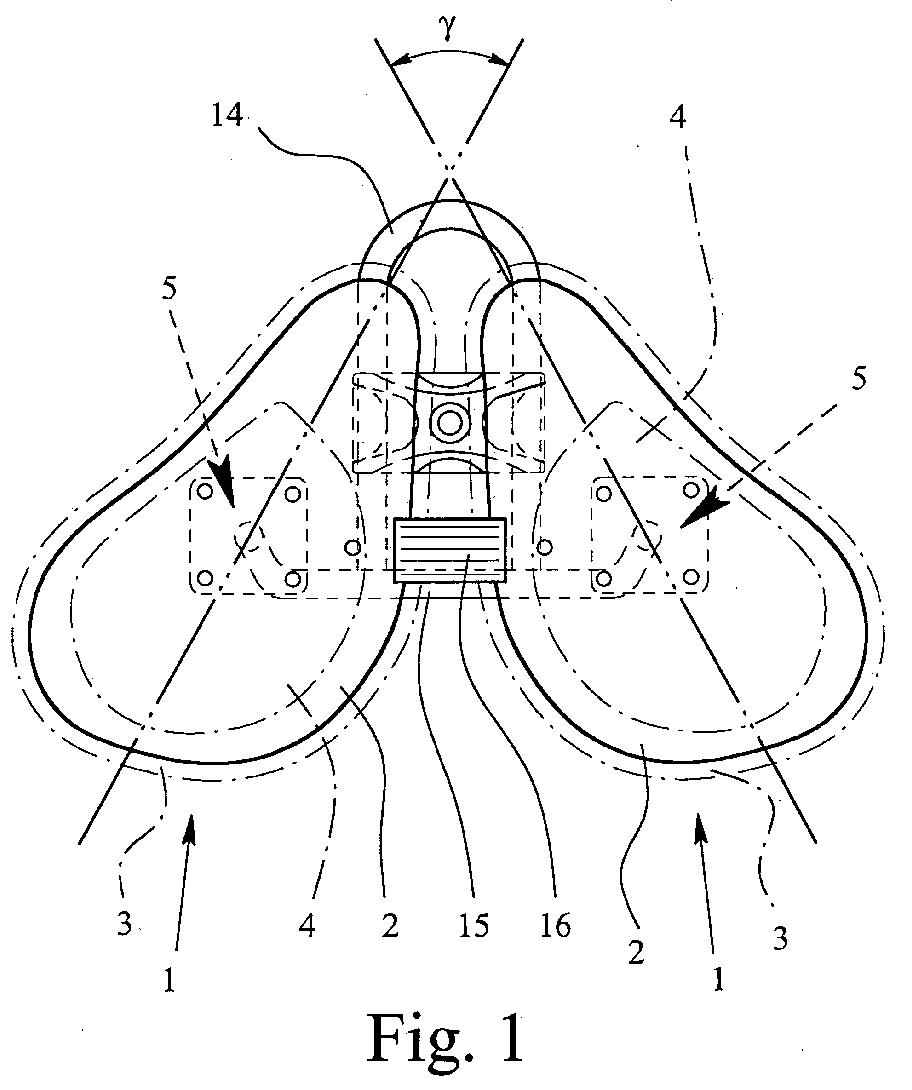
- Fig. 1
- eine Draufsicht auf einen Sattel gemäß einem bevorzugten Ausführungsbeispiel der Erfindung,
- Fig. 2
- eine Seitenansicht des Sattels gemäß dem bevorzugten Ausführungsbeispiel der Erfindung,
- Fig. 3
- eine Seitenansicht des Sattels gemäß dem bevorzugten Ausführungsbeispiel der Erfindung mit abgenommenen Sitzhälften,
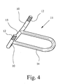
- Fig. 4
- das Trägergestänge des Sattels gemäß dem bevorzugten Ausführungsbeispiel der Erfindung in einer perspektivischen Ansicht,
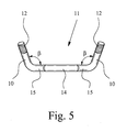
- Fig. 5
- das Trägergestänge des Sattels gemäß dem bevorzugten Ausführungsbeispiel der Erfindung in einer Ansicht von vorne und
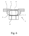
- Fig. 6
- die Kalottengelenkanordnung des Sattels gemäß dem bevorzugten Ausführungsbeispiel der Erfindung im Schnitt.
- Fig. 1
- 3 shows a plan view of a saddle according to a preferred exemplary embodiment of the invention,
- Fig. 2
- a side view of the saddle according to the preferred embodiment of the invention,
- Fig. 3
- 2 shows a side view of the saddle according to the preferred exemplary embodiment of the invention with the seat halves removed,
- Fig. 4
- the carrier linkage of the saddle according to the preferred embodiment of the invention in a perspective view,
- Fig. 5
- the support rod of the saddle according to the preferred embodiment of the invention in a view from the front and
- Fig. 6
- the calotte joint arrangement of the saddle according to the preferred embodiment of the invention in section.
Aus Fig. 1 ist ein Fahrradsattel gemäß einem bevorzugten Ausführungsbeispiel
der Erfindung in einer Draufsicht ersichtlich, wobei der Sattel zwei im
Abstand voneinander angeordnete und für jeweils eine Gesäßhälfte vorgesehene
Sitzhälften 1 aufweist. Wie insbesondere aus Fig. 2 ersichtlich, weisen
die Sitzhälften 1 jeweils eine Bodenplatte 2 sowie eine Polsterung 3 auf. Aus
Komfortgründen ist die Polsterung 3 mit einem Gel-Einsatz 4 versehen. Der
Gel-Einsatz 4 dient im wesentlichen zur Entlastung der scharfkantigen Sitzknochen.
Diese bestimmen im wesentlichen auch den Abstand der beiden
Sitzhälften 1 voneinander bzw. den Ort der Polsterung 3: Der Abstand der
Sitzknochen beträgt bei einem erwachsenen Menschen typischerweise maximal
90 mm, wobei sich der Abstand nach vorne auf ca. 40 mm verringert, so
daß Abstand, Breit und Länge der Sitzhälften danach bemessen werden. Die
Polsterung 3 und der Gel-Einsatz 4 sind schließlich mit einem nicht weiter
dargestellten Bezug aus z. B. Leder oder einem Kunstledermaterial überzogen.
Im übrigen kann auch vorgesehen sein, daß Polsterung 3, Gel-Einsatz 4 und
der Bezug als eine Einheit vorgesehen sind, die lösbar auf der Bodenplatte 2
befestigbar ist, z. B. mittels eines nicht weiter dargestellten Klettverschlusses.1 is a bicycle saddle according to a preferred embodiment
of the invention in a plan view, the saddle two in
Distance from each other and provided for one
Auf den Unterseiten der Sitzhälften 1 ist jeweils eine Kalottengelenkanordnung
5 in Form eines Flanschlager vorgesehen. Die Kalottengelenkanordnungen
5 sind mit den Bodenplatten 2 verschraubt, können mit den Bodenplatten
2 jedoch auch einstückig ausgebildet sein. Dabei sind die Bodenplatten 2 vorzugsweise
aus GFK hergestellt.On the undersides of the seat halves 1 there is a spherical
Wie insbesondere aus Fig. 6 ersichtlich, weist die Kalottengelenkanordnung 5
eine im wesentlichen hohlkugelförmige Pfanne 6 und ein darin bewegbares
Kalottenelement 7 auf. Das Kalottenelement 7 weist als Einrichtungen zur Beschränkung
des Bewegungsbereichs der Kalottenelemente 7 in der Pfanne 6
an seinem oberen Ende und an seinem unteren Ende jeweils einen Kragen 8
auf, der am Ende des Bewegungsbereichs mit dem Rand der Pfanne 6 in Anschlag
kommt. Dabei sind der Rand der Pfanne 6 und der am Ende des Bewegungsbereichs
mit dem Rand der Pfanne 6 in Anschlag kommende Kragen 8
des Kalottenelements 7 winkelmäßig derart aneinander angepaßt, daß es zu
einer ausgedehnten Auflage des Kragens 8 des Kalottenelements 7 auf dem
Rand der Pfanne 6 kommt.As can be seen in particular from FIG. 6, the spherical joint arrangement 5
a substantially hollow
Die Kalottenelemente 7 sind jeweils mit einem Innengewinde 9 versehen. In
dieses Innengewinde 9 sind die Enden der Träger 10 des Trägergestänges 11,
die jeweils ein entsprechendes Außengewinde 12 aufweisen, eingeschraubt, so
daß insgesamt die Sitzhälften 1 des Sattels über das Trägergestänge 11 mit einer
herkömmlichen Sattelstütze 13 verbindbar sind. Zum Einschrauben der
Träger 10 in die Kalottenelemente 7 dient jeweils ein Montageabschnitt 17.
Zur Verbindung mit der herkömmlichen Sattelstütze 13 dient ein im wesentlichen
U-förmiger Abschnitt 14 des Trägergestänges 11, wie insbesondere Fig.
1 entnehmbar.The
Insbesondere Fig. 5 ist nun entnehmbar, daß die Träger 10 jeweils nach außen
geneigt sind, vorliegend nämlich gegenüber einem die beiden Träger 10 verbindenden
Abschnitt 15 des Trägergestänges 11 jeweils einen Winkel β von
ca. 100° einschließen. Damit sind die Kalottengelenkachsen, um die die Kalottenelemente
7 in ihrer jeweiligen Pfanne 6 bewegbar sind, ebenfalls nach
außen geneigt, wodurch die Sitzhälften 1, gemessen an der Horizontalen, weniger
nach innen als nach außen verkippbar sind.In particular Fig. 5 can now be seen that the
Außerdem sind die Träger 10 in an der Sattelstütze 13 montiertem Zustand
auch nach vorne geneigt, was, ebenfalls gemessen an der Horizontalen nur ein
geringes Verkippen nach hinten, jedoch ein stärkeres Verkippen nach vorne
der Sitzhälften 1 zur Folge hat. Der Winkel α zwischen den Trägern 10 und
dem U-förmigen Abschnitt 14 des Trägergestänges 11 beträgt bei dem hier
beschriebenen bevorzugten Ausführungsbeispiel der Erfindung jeweils 74°.
Die damit verbundenen Vorteile sind schon weiter oben im einzelnen ausgeführt
worden. Um die beiden Sitzhälften 1 im unbelasteten Zustand, also z. B.
zum Aufsteigen, in einer geeigneten Position zu fixieren, ist schließlich zwischen
den beiden Sitzhälften 1 ein elastischer Abstandshalter 16 in Form eines
Gummibandes vorgesehen.In addition, the
Die beiden Sitzhälften 1 sind, von oben betrachtet, im wesentlichen halbherzförmig
ausgebildet, wobei sie jeweils eine nach vorne zeigende, kurze und abgerundete
Spitze aufweisen. Die einander zugewandten Ränder der beiden
Sitzhälften 1 verlaufen im wesentlichen parallel zueinander. Die in Fig. 1 eingezeichneten
Hauptachsen längs der jeweils größten Erstreckung der Sitzhälften
1 schließen bei dem vorliegend beschriebenen bevorzugten Ausführungsbeispiel
der Erfmdung einen Winkel von γ = 57° ein. Damit wird durch
die beiden Sitzhälften 1 den beiden Gesäßknochen mit umliegendem Muskelund
Weichteilgewebe hinreichend Halt geboten, wobei die abgerundeten Spitzen
der Sitzhälften 1 nur kurz sind und damit nur eine minimale Fläche der
Innenseite der Oberschenkel berühren, um die Beinführung zu gewährleisten.
Dadurch sind Druckstellen im Genitalbereich ausgeschlossen.When viewed from above, the two
Durch den Abstand der beiden Sitzhälften 1 voneinander von ca. 2 cm im
Gleichgewichtszustand wird auch ein indirekter Druck durch Aufliegen der
beiden Gesäßhälften gegen den Schließmuskel und damit gegen die Prostata
weitestgehend reduziert. Ein direkter Druck auf den Schließmuskel und den
Damm einschließlich der Harnröhre wird durch den Abstand der beiden Sitzhälften
1 voneinander praktisch vollständig ausgeschlossen. Auch für den
weiblichen Radfahrer sind die Entlastung der Druckstellen von gesundheitlicher
Bedeutung. Insbesondere ist für den weiblichen Radfahrer auch keine
grundsätzliche Änderung des Sattels erforderlich. Bei Kindersätteln müssen
lediglich die Proportionen verändert werden. Der erfindungsgemäße Sattel ist
selbstverständlich auch für Ergometer geeignet.Due to the distance between the two
Claims (9)
Applications Claiming Priority (2)
| Application Number | Priority Date | Filing Date | Title |
|---|---|---|---|
| DE10309352A DE10309352B4 (en) | 2003-03-03 | 2003-03-03 | saddle |
| DE10309352 | 2003-03-03 |
Publications (3)
| Publication Number | Publication Date |
|---|---|
| EP1454823A2 true EP1454823A2 (en) | 2004-09-08 |
| EP1454823A3 EP1454823A3 (en) | 2005-09-14 |
| EP1454823B1 EP1454823B1 (en) | 2009-04-08 |
Family
ID=32797797
Family Applications (1)
| Application Number | Title | Priority Date | Filing Date |
|---|---|---|---|
| EP04003146A Expired - Lifetime EP1454823B1 (en) | 2003-03-03 | 2004-02-12 | Saddle |
Country Status (4)
| Country | Link |
|---|---|
| US (1) | US7104600B2 (en) |
| EP (1) | EP1454823B1 (en) |
| AT (1) | ATE427873T1 (en) |
| DE (2) | DE10309352B4 (en) |
Cited By (2)
| Publication number | Priority date | Publication date | Assignee | Title |
|---|---|---|---|---|
| NL1035931C (en) * | 2008-09-12 | 2010-03-16 | Johan Bernhard Steege | SADDLE FOR A DEVICE EQUIPPED WITH TRAPPERS. |
| WO2020041643A1 (en) | 2018-08-22 | 2020-02-27 | BCS Group | Seat frame for securement on a support surface |
Families Citing this family (54)
| Publication number | Priority date | Publication date | Assignee | Title |
|---|---|---|---|---|
| JP3918936B2 (en) * | 2003-03-13 | 2007-05-23 | セイコーエプソン株式会社 | Electronic device and manufacturing method thereof, circuit board, and electronic apparatus |
| DE102004021795A1 (en) * | 2004-05-03 | 2005-12-01 | Rainer Ebid | Three-dimensional rotation unit for e.g. saddle of bicycle, has repositioning unit at saddle that contacts protrusion on upper surface of ball when repositioning spring connecting ball bearings to saddle is in released position |
| ITVI20050025A1 (en) * | 2005-01-28 | 2006-07-29 | Selle Royal Spa | ERGONOMIC SUPPORT STRUCTURE IN COMPOSITE MATERIAL, PARTICULARLY FOR SUPPORTING PARTS OF THE HUMAN BODY, AS WELL AS THE METHOD OF REALIZING THE SAME |
| ITMI20060196A1 (en) * | 2006-02-06 | 2007-08-07 | Selle Italia Srl | PERFECT SADDLE PROVIDED WITH A DEVICE FOR ITS CYCLE AND SIMILAR APPLICATION |
| US7494181B2 (en) * | 2006-09-05 | 2009-02-24 | Samuel Tucker | Bicycle seat |
| US20080169689A1 (en) * | 2007-01-17 | 2008-07-17 | Keng Chien-Kuo | Bicycle seat |
| DE102009005153B4 (en) * | 2009-01-15 | 2015-12-17 | Hans Scholz | saddle |
| USD609480S1 (en) | 2009-07-01 | 2010-02-09 | Ascher Steven G | Seat |
| USD639081S1 (en) | 2010-04-23 | 2011-06-07 | Tampa Bay Recreation, Llc | Bicycle seat |
| USD722446S1 (en) | 2012-03-06 | 2015-02-17 | Tampa Bay Recreation, Llc | Bicycle seat |
| TWM442310U (en) * | 2012-03-29 | 2012-12-01 | shi-yuan Zeng | Flight airfoil seat structure |
| USD720939S1 (en) | 2012-08-28 | 2015-01-13 | Tampa Bay Recreation, Llc | Bicycle seat |
| BE1022271B1 (en) * | 2013-08-13 | 2016-03-08 | PASQUIER, Philippe | ERGONOMIC ASSIE FOR CYCLE |
| US20150173515A1 (en) * | 2013-12-23 | 2015-06-25 | Freedman Seats Ltd | Seat |
| USD724330S1 (en) | 2014-03-05 | 2015-03-17 | Tampa Bay Recreation, Llc | Bicycle seat |
| USD764822S1 (en) | 2014-03-05 | 2016-08-30 | Ism Saddles, Llc | Bicycle seat |
| USD764821S1 (en) | 2014-03-05 | 2016-08-30 | Ism Saddles, Llc | Bicycle seat |
| USD724329S1 (en) | 2014-03-05 | 2015-03-17 | Tampa Bay Recreation, Llc | Bicycle seat |
| USD767909S1 (en) | 2014-08-05 | 2016-10-04 | Ism Saddles, Llc | Bicycle seat |
| USD767911S1 (en) | 2014-08-05 | 2016-10-04 | Ism Saddles, Llc | Bicycle seat |
| USD769007S1 (en) | 2014-08-05 | 2016-10-18 | Ism Saddles, Llc | Bicycle seat |
| USD767910S1 (en) | 2014-08-05 | 2016-10-04 | Ism Saddles, Llc | Bicycle seat |
| USD764820S1 (en) | 2014-08-15 | 2016-08-30 | Ism Saddles, Llc | Bicycle seat |
| USD769631S1 (en) | 2014-08-18 | 2016-10-25 | Ism Saddles, Llc | Bicycle seat |
| USD769008S1 (en) | 2014-08-18 | 2016-10-18 | Ism Saddles, Llc | Bicycle seat |
| US20160167726A1 (en) * | 2014-12-10 | 2016-06-16 | II Jackson C. Dudley | Bicycle saddle |
| USD786573S1 (en) | 2015-03-13 | 2017-05-16 | Ism Saddles, Llc | Bicycle seat |
| US9573643B1 (en) * | 2015-08-28 | 2017-02-21 | S R Schwary | Bicycle seat assembly |
| EP3350068B1 (en) * | 2015-09-14 | 2021-08-18 | Jon A. Petty | Adjustable saddle |
| US9821867B2 (en) * | 2016-02-11 | 2017-11-21 | Jared S. Goff | Bicycle seat |
| USD802949S1 (en) | 2016-08-23 | 2017-11-21 | Ism Saddles, Llc | Bicycle seat |
| USD806415S1 (en) | 2016-08-26 | 2018-01-02 | Ism Saddles, Llc | Bicycle seat |
| CN109689485B (en) | 2016-08-26 | 2020-05-12 | 伊斯姆座垫有限责任公司 | bicycle seat with ventilation system |
| USD803594S1 (en) | 2016-08-26 | 2017-11-28 | Ism Saddles, Llc | Bicycle seat |
| DE102016012073A1 (en) | 2016-10-10 | 2018-04-12 | Axel Kraaz | Saddle arrangement for a pedal-driven device |
| USD846897S1 (en) | 2017-07-24 | 2019-04-30 | Ism Saddles, Llc | Bicycle seat |
| USD846899S1 (en) | 2017-09-22 | 2019-04-30 | Ism Saddles, Llc | Bicycle seat |
| USD880880S1 (en) | 2018-02-02 | 2020-04-14 | Ism Saddles, Llc | Bicycle seat |
| USD846900S1 (en) | 2018-02-22 | 2019-04-30 | Ism Saddles, Llc | Bicycle seat |
| DE102018108381A1 (en) | 2018-04-09 | 2019-10-10 | Axel Kraaz | Muscle force drive and device with a muscle power drive |
| USD889862S1 (en) | 2018-06-12 | 2020-07-14 | Ism Saddles, Llc | Bicycle seat |
| US11052958B2 (en) * | 2018-10-02 | 2021-07-06 | Xsensor Technology Corporation | Bicycle seats |
| US11760431B2 (en) | 2018-10-02 | 2023-09-19 | Xsensor Technology Corporation | Bicycle seat for improved comfort, performance, and safety |
| USD904049S1 (en) | 2019-03-22 | 2020-12-08 | Ism Saddles, Llc | Bicycle seat |
| USD903348S1 (en) | 2019-08-16 | 2020-12-01 | Ism Saddles, Llc | Bicycle seat |
| WO2021140473A1 (en) * | 2020-01-10 | 2021-07-15 | James Colthurst | Ergonomically designed bicycle saddle |
| EP4087773B1 (en) * | 2020-01-10 | 2025-12-17 | James Colthurst | Ergonomically designed bicycle saddle |
| KR102128753B1 (en) * | 2020-05-25 | 2020-07-02 | 이명석 | Bicycle dual saddle and bicycle with the same |
| US12151759B2 (en) * | 2020-10-09 | 2024-11-26 | Jian Xiang OUYANG | Adjustable seat for bicycle, exercise machine or the like |
| IT202200004652A1 (en) * | 2022-03-10 | 2023-09-10 | Romanutti Daniele | SADDLE FOR BICYCLES AND SIMILAR EQUIPMENT |
| USD1012521S1 (en) | 2022-07-19 | 2024-01-30 | Ism Saddles, Llc | Bicycle seat |
| USD1012522S1 (en) | 2022-07-19 | 2024-01-30 | Adamo Island Saddles, Llc | Bicycle seat |
| USD1012523S1 (en) | 2022-07-19 | 2024-01-30 | Adamo Island Saddles, Llc | Bicycle seat |
| USD1020543S1 (en) | 2022-07-19 | 2024-04-02 | Adamo Island Saddles, Llc | Bicycle seat |
Family Cites Families (22)
| Publication number | Priority date | Publication date | Assignee | Title |
|---|---|---|---|---|
| DE93478C (en) * | ||||
| DE101448C (en) * | ||||
| US608682A (en) * | 1898-08-09 | Cycle-saddle | ||
| US621139A (en) * | 1899-03-14 | Bicycle-saddle | ||
| US694875A (en) * | 1901-10-04 | 1902-03-04 | George A Meighan | Bicycle-saddle. |
| DE827008C (en) * | 1949-11-01 | 1952-01-07 | Willy Messerschmitt Dr Ing | Saddle for bicycles or the like |
| US4387925A (en) * | 1980-06-30 | 1983-06-14 | J. B. Two Corporation | Bicycle seat |
| US5123698A (en) * | 1990-10-25 | 1992-06-23 | Martec Development, Inc. | Bicycle seat with adjustable support platforms |
| CA2081619A1 (en) * | 1991-11-08 | 1993-05-09 | Keith Hellon | Ball joint assembly and method of construction |
| US5492428A (en) * | 1991-11-08 | 1996-02-20 | Maclean-Fogg Company | Ball joint assembly |
| US5722718A (en) * | 1995-09-08 | 1998-03-03 | Catamount Cycles Ii Llc | Seat mounting assembly |
| DE29517194U1 (en) * | 1995-10-23 | 1996-01-25 | Stahlberg, Wilhelm, 38321 Denkte | Cup bike saddle |
| DE29608190U1 (en) * | 1996-05-06 | 1996-08-01 | Funke, Dennis, 47627 Kevelaer | Bicycle saddle with two movable seats |
| US6164861A (en) * | 1998-03-13 | 2000-12-26 | Dana Corporation | Bearing set for a ball joint assembly |
| US6082923A (en) * | 1998-03-16 | 2000-07-04 | Dana Corporation | Converging sphere joint assembly |
| US6056356A (en) * | 1998-08-17 | 2000-05-02 | Unger, Jr.; Joseph F. | Cycle seat |
| US6402235B1 (en) * | 1998-09-04 | 2002-06-11 | Rodger B. Letendre | Split bicycle seat |
| US6209954B1 (en) * | 1999-06-21 | 2001-04-03 | James H. Bombardier | Bicycle saddle |
| US6068333A (en) * | 1999-08-06 | 2000-05-30 | Dixon; Jeffrey | Dual support unit bicycle seat |
| ES2156090B1 (en) * | 1999-10-08 | 2002-02-16 | Marfa Juan Maragall | PERFECTED BIKE SADDLE. |
| DE20100412U1 (en) * | 2001-01-11 | 2001-06-13 | Postel, Peter, Dipl.-Ing., 82467 Garmisch-Partenkirchen | Bicycle saddle with two independently movable seat parts |
| DE20212353U1 (en) * | 2002-08-10 | 2002-11-07 | Becker, Wolfgang, 34260 Kaufungen | One-piece bicycle saddle |
-
2003
- 2003-03-03 DE DE10309352A patent/DE10309352B4/en not_active Expired - Fee Related
-
2004
- 2004-02-12 DE DE502004009295T patent/DE502004009295D1/en not_active Expired - Lifetime
- 2004-02-12 AT AT04003146T patent/ATE427873T1/en not_active IP Right Cessation
- 2004-02-12 EP EP04003146A patent/EP1454823B1/en not_active Expired - Lifetime
- 2004-03-01 US US10/788,477 patent/US7104600B2/en not_active Expired - Fee Related
Cited By (3)
| Publication number | Priority date | Publication date | Assignee | Title |
|---|---|---|---|---|
| NL1035931C (en) * | 2008-09-12 | 2010-03-16 | Johan Bernhard Steege | SADDLE FOR A DEVICE EQUIPPED WITH TRAPPERS. |
| WO2020041643A1 (en) | 2018-08-22 | 2020-02-27 | BCS Group | Seat frame for securement on a support surface |
| EP3840985A4 (en) * | 2018-08-22 | 2022-09-07 | BCS Group | Seat frame for securement on a support surface |
Also Published As
| Publication number | Publication date |
|---|---|
| ATE427873T1 (en) | 2009-04-15 |
| DE502004009295D1 (en) | 2009-05-20 |
| EP1454823A3 (en) | 2005-09-14 |
| DE10309352B4 (en) | 2007-11-22 |
| US7104600B2 (en) | 2006-09-12 |
| EP1454823B1 (en) | 2009-04-08 |
| US20040174051A1 (en) | 2004-09-09 |
| DE10309352A1 (en) | 2004-09-23 |
Similar Documents
| Publication | Publication Date | Title |
|---|---|---|
| DE10309352B4 (en) | saddle | |
| DE69903128T2 (en) | BICYCLE SADDLE | |
| DE69921149T2 (en) | BICYCLE SEAT | |
| DE2545999A1 (en) | CHAIR WITH SWIVELING BACKREST AND LEGS HINGED TO THE CHAIR FRAME | |
| DE102005016390B4 (en) | vehicle seat | |
| DE102017123727A1 (en) | bicycle saddle | |
| DE69913042T2 (en) | bicycle seat | |
| WO2013186157A1 (en) | Active dynamic stool | |
| EP2571400B1 (en) | Chair with a tilting apparatus | |
| EP2451318B1 (en) | Seat with body supporting device | |
| DE69432301T2 (en) | BICYCLE SADDLE | |
| DE102010036593A1 (en) | Ergonomic seating surface and seating | |
| WO2011058430A2 (en) | Seat body for fitness equipment suited for strength training | |
| DE20212353U1 (en) | One-piece bicycle saddle | |
| DE20320525U1 (en) | Saddle for pedal operated device such as bicycle has ball joint axis angled outwards to enable ball elements to move in their pan | |
| DE1152232B (en) | Seats, especially work seats, with a rear, wedge-like rising support surface for stools, chairs or the like | |
| DE3440985A1 (en) | Orthopaedically optimised vehicle seat | |
| DE20001307U1 (en) | Office fitness chair | |
| DE102013003746A1 (en) | Chair, strength training device and use of a chair as a strength training device | |
| DE102020124398B4 (en) | Training device for training individual muscle groups in the upper body | |
| DE60222398T2 (en) | Device for muscle training of a person | |
| DE102010012659A1 (en) | Seat device, particularly for therapy of person, has frame, on which seat element is arranged, where seat element has saddle-shaped seating surface | |
| DE29900832U1 (en) | Movable bicycle saddle | |
| EP1855570A1 (en) | Work stool | |
| EP3369648A1 (en) | System for a balance bike or a bicycle and a corresponding balance bike or bicycle |
Legal Events
| Date | Code | Title | Description |
|---|---|---|---|
| PUAI | Public reference made under article 153(3) epc to a published international application that has entered the european phase |
Free format text: ORIGINAL CODE: 0009012 |
|
| AK | Designated contracting states |
Kind code of ref document: A2 Designated state(s): AT BE BG CH CY CZ DE DK EE ES FI FR GB GR HU IE IT LI LU MC NL PT RO SE SI SK TR |
|
| AX | Request for extension of the european patent |
Extension state: AL LT LV MK |
|
| PUAL | Search report despatched |
Free format text: ORIGINAL CODE: 0009013 |
|
| AK | Designated contracting states |
Kind code of ref document: A3 Designated state(s): AT BE BG CH CY CZ DE DK EE ES FI FR GB GR HU IE IT LI LU MC NL PT RO SE SI SK TR |
|
| AX | Request for extension of the european patent |
Extension state: AL LT LV MK |
|
| AKX | Designation fees paid | ||
| 17P | Request for examination filed |
Effective date: 20060517 |
|
| RBV | Designated contracting states (corrected) |
Designated state(s): AT BE BG CH CY CZ DE DK EE ES FI FR GB GR HU IE IT LI LU MC NL PT RO SE SI SK TR |
|
| 17Q | First examination report despatched |
Effective date: 20071109 |
|
| GRAP | Despatch of communication of intention to grant a patent |
Free format text: ORIGINAL CODE: EPIDOSNIGR1 |
|
| GRAS | Grant fee paid |
Free format text: ORIGINAL CODE: EPIDOSNIGR3 |
|
| GRAA | (expected) grant |
Free format text: ORIGINAL CODE: 0009210 |
|
| AK | Designated contracting states |
Kind code of ref document: B1 Designated state(s): AT BE BG CH CY CZ DE DK EE ES FI FR GB GR HU IE IT LI LU MC NL PT RO SE SI SK TR |
|
| REG | Reference to a national code |
Ref country code: GB Ref legal event code: FG4D Free format text: NOT ENGLISH |
|
| REG | Reference to a national code |
Ref country code: CH Ref legal event code: EP |
|
| REG | Reference to a national code |
Ref country code: IE Ref legal event code: FG4D |
|
| REF | Corresponds to: |
Ref document number: 502004009295 Country of ref document: DE Date of ref document: 20090520 Kind code of ref document: P |
|
| PG25 | Lapsed in a contracting state [announced via postgrant information from national office to epo] |
Ref country code: SI Free format text: LAPSE BECAUSE OF FAILURE TO SUBMIT A TRANSLATION OF THE DESCRIPTION OR TO PAY THE FEE WITHIN THE PRESCRIBED TIME-LIMIT Effective date: 20090408 |
|
| NLV1 | Nl: lapsed or annulled due to failure to fulfill the requirements of art. 29p and 29m of the patents act | ||
| REG | Reference to a national code |
Ref country code: IE Ref legal event code: FD4D |
|
| PG25 | Lapsed in a contracting state [announced via postgrant information from national office to epo] |
Ref country code: FI Free format text: LAPSE BECAUSE OF FAILURE TO SUBMIT A TRANSLATION OF THE DESCRIPTION OR TO PAY THE FEE WITHIN THE PRESCRIBED TIME-LIMIT Effective date: 20090408 Ref country code: ES Free format text: LAPSE BECAUSE OF FAILURE TO SUBMIT A TRANSLATION OF THE DESCRIPTION OR TO PAY THE FEE WITHIN THE PRESCRIBED TIME-LIMIT Effective date: 20090719 Ref country code: PT Free format text: LAPSE BECAUSE OF FAILURE TO SUBMIT A TRANSLATION OF THE DESCRIPTION OR TO PAY THE FEE WITHIN THE PRESCRIBED TIME-LIMIT Effective date: 20090908 |
|
| PG25 | Lapsed in a contracting state [announced via postgrant information from national office to epo] |
Ref country code: NL Free format text: LAPSE BECAUSE OF FAILURE TO SUBMIT A TRANSLATION OF THE DESCRIPTION OR TO PAY THE FEE WITHIN THE PRESCRIBED TIME-LIMIT Effective date: 20090408 Ref country code: SE Free format text: LAPSE BECAUSE OF FAILURE TO SUBMIT A TRANSLATION OF THE DESCRIPTION OR TO PAY THE FEE WITHIN THE PRESCRIBED TIME-LIMIT Effective date: 20090708 |
|
| PG25 | Lapsed in a contracting state [announced via postgrant information from national office to epo] |
Ref country code: CZ Free format text: LAPSE BECAUSE OF FAILURE TO SUBMIT A TRANSLATION OF THE DESCRIPTION OR TO PAY THE FEE WITHIN THE PRESCRIBED TIME-LIMIT Effective date: 20090408 Ref country code: IE Free format text: LAPSE BECAUSE OF FAILURE TO SUBMIT A TRANSLATION OF THE DESCRIPTION OR TO PAY THE FEE WITHIN THE PRESCRIBED TIME-LIMIT Effective date: 20090408 Ref country code: EE Free format text: LAPSE BECAUSE OF FAILURE TO SUBMIT A TRANSLATION OF THE DESCRIPTION OR TO PAY THE FEE WITHIN THE PRESCRIBED TIME-LIMIT Effective date: 20090408 Ref country code: RO Free format text: LAPSE BECAUSE OF FAILURE TO SUBMIT A TRANSLATION OF THE DESCRIPTION OR TO PAY THE FEE WITHIN THE PRESCRIBED TIME-LIMIT Effective date: 20090408 Ref country code: DK Free format text: LAPSE BECAUSE OF FAILURE TO SUBMIT A TRANSLATION OF THE DESCRIPTION OR TO PAY THE FEE WITHIN THE PRESCRIBED TIME-LIMIT Effective date: 20090408 |
|
| PLBE | No opposition filed within time limit |
Free format text: ORIGINAL CODE: 0009261 |
|
| STAA | Information on the status of an ep patent application or granted ep patent |
Free format text: STATUS: NO OPPOSITION FILED WITHIN TIME LIMIT |
|
| PG25 | Lapsed in a contracting state [announced via postgrant information from national office to epo] |
Ref country code: SK Free format text: LAPSE BECAUSE OF FAILURE TO SUBMIT A TRANSLATION OF THE DESCRIPTION OR TO PAY THE FEE WITHIN THE PRESCRIBED TIME-LIMIT Effective date: 20090408 |
|
| 26N | No opposition filed |
Effective date: 20100111 |
|
| PG25 | Lapsed in a contracting state [announced via postgrant information from national office to epo] |
Ref country code: BG Free format text: LAPSE BECAUSE OF FAILURE TO SUBMIT A TRANSLATION OF THE DESCRIPTION OR TO PAY THE FEE WITHIN THE PRESCRIBED TIME-LIMIT Effective date: 20090708 |
|
| BERE | Be: lapsed |
Owner name: SCHOLZ, HANS Effective date: 20100228 |
|
| REG | Reference to a national code |
Ref country code: CH Ref legal event code: PL |
|
| GBPC | Gb: european patent ceased through non-payment of renewal fee |
Effective date: 20100212 |
|
| PG25 | Lapsed in a contracting state [announced via postgrant information from national office to epo] |
Ref country code: LI Free format text: LAPSE BECAUSE OF NON-PAYMENT OF DUE FEES Effective date: 20100228 Ref country code: GR Free format text: LAPSE BECAUSE OF FAILURE TO SUBMIT A TRANSLATION OF THE DESCRIPTION OR TO PAY THE FEE WITHIN THE PRESCRIBED TIME-LIMIT Effective date: 20090709 Ref country code: CH Free format text: LAPSE BECAUSE OF NON-PAYMENT OF DUE FEES Effective date: 20100228 Ref country code: MC Free format text: LAPSE BECAUSE OF NON-PAYMENT OF DUE FEES Effective date: 20100301 |
|
| PG25 | Lapsed in a contracting state [announced via postgrant information from national office to epo] |
Ref country code: BE Free format text: LAPSE BECAUSE OF NON-PAYMENT OF DUE FEES Effective date: 20100228 |
|
| PG25 | Lapsed in a contracting state [announced via postgrant information from national office to epo] |
Ref country code: GB Free format text: LAPSE BECAUSE OF NON-PAYMENT OF DUE FEES Effective date: 20100212 |
|
| PG25 | Lapsed in a contracting state [announced via postgrant information from national office to epo] |
Ref country code: AT Free format text: LAPSE BECAUSE OF NON-PAYMENT OF DUE FEES Effective date: 20100212 |
|
| PG25 | Lapsed in a contracting state [announced via postgrant information from national office to epo] |
Ref country code: CY Free format text: LAPSE BECAUSE OF FAILURE TO SUBMIT A TRANSLATION OF THE DESCRIPTION OR TO PAY THE FEE WITHIN THE PRESCRIBED TIME-LIMIT Effective date: 20090408 |
|
| PG25 | Lapsed in a contracting state [announced via postgrant information from national office to epo] |
Ref country code: LU Free format text: LAPSE BECAUSE OF NON-PAYMENT OF DUE FEES Effective date: 20100212 Ref country code: HU Free format text: LAPSE BECAUSE OF FAILURE TO SUBMIT A TRANSLATION OF THE DESCRIPTION OR TO PAY THE FEE WITHIN THE PRESCRIBED TIME-LIMIT Effective date: 20091009 |
|
| PG25 | Lapsed in a contracting state [announced via postgrant information from national office to epo] |
Ref country code: TR Free format text: LAPSE BECAUSE OF FAILURE TO SUBMIT A TRANSLATION OF THE DESCRIPTION OR TO PAY THE FEE WITHIN THE PRESCRIBED TIME-LIMIT Effective date: 20090408 |
|
| PGFP | Annual fee paid to national office [announced via postgrant information from national office to epo] |
Ref country code: FR Payment date: 20140219 Year of fee payment: 11 Ref country code: IT Payment date: 20140224 Year of fee payment: 11 |
|
| REG | Reference to a national code |
Ref country code: FR Ref legal event code: ST Effective date: 20151030 |
|
| PG25 | Lapsed in a contracting state [announced via postgrant information from national office to epo] |
Ref country code: IT Free format text: LAPSE BECAUSE OF NON-PAYMENT OF DUE FEES Effective date: 20150212 |
|
| PG25 | Lapsed in a contracting state [announced via postgrant information from national office to epo] |
Ref country code: FR Free format text: LAPSE BECAUSE OF NON-PAYMENT OF DUE FEES Effective date: 20150302 |
|
| REG | Reference to a national code |
Ref country code: DE Ref legal event code: R082 Ref document number: 502004009295 Country of ref document: DE Representative=s name: HANNKE BITTNER & PARTNER, PATENT- UND RECHTSAN, DE |
|
| REG | Reference to a national code |
Ref country code: DE Ref legal event code: R081 Ref document number: 502004009295 Country of ref document: DE Owner name: HYPERVITAL AG, CH Free format text: FORMER OWNER: SCHOLZ, HANS, 53474 BAD NEUENAHR-AHRWEILER, DE Ref country code: DE Ref legal event code: R082 Ref document number: 502004009295 Country of ref document: DE Representative=s name: HANNKE BITTNER & PARTNER, PATENT- UND RECHTSAN, DE Ref country code: DE Ref legal event code: R081 Ref document number: 502004009295 Country of ref document: DE Owner name: HYPERVITAL GMBH, DE Free format text: FORMER OWNER: SCHOLZ, HANS, 53474 BAD NEUENAHR-AHRWEILER, DE |
|
| REG | Reference to a national code |
Ref country code: DE Ref legal event code: R082 Ref document number: 502004009295 Country of ref document: DE Representative=s name: HANNKE BITTNER & PARTNER, PATENT- UND RECHTSAN, DE Ref country code: DE Ref legal event code: R081 Ref document number: 502004009295 Country of ref document: DE Owner name: HYPERVITAL AG, CH Free format text: FORMER OWNER: HYPERVITAL GMBH, 87448 WALTENHOFEN, DE |
|
| PGFP | Annual fee paid to national office [announced via postgrant information from national office to epo] |
Ref country code: DE Payment date: 20230126 Year of fee payment: 20 |
|
| REG | Reference to a national code |
Ref country code: DE Ref legal event code: R071 Ref document number: 502004009295 Country of ref document: DE |