EP1454855A2 - Verfahren und Vorrichtung zur Übergabe von Artikeln von einer ersten zu einer zweiten, nachgeordneten Förderlinie - Google Patents
Verfahren und Vorrichtung zur Übergabe von Artikeln von einer ersten zu einer zweiten, nachgeordneten Förderlinie Download PDFInfo
- Publication number
- EP1454855A2 EP1454855A2 EP04004468A EP04004468A EP1454855A2 EP 1454855 A2 EP1454855 A2 EP 1454855A2 EP 04004468 A EP04004468 A EP 04004468A EP 04004468 A EP04004468 A EP 04004468A EP 1454855 A2 EP1454855 A2 EP 1454855A2
- Authority
- EP
- European Patent Office
- Prior art keywords
- line
- bar
- article
- movement
- trajectory
- Prior art date
- Legal status (The legal status is an assumption and is not a legal conclusion. Google has not performed a legal analysis and makes no representation as to the accuracy of the status listed.)
- Withdrawn
Links
Images



Classifications
-
- B—PERFORMING OPERATIONS; TRANSPORTING
- B65—CONVEYING; PACKING; STORING; HANDLING THIN OR FILAMENTARY MATERIAL
- B65G—TRANSPORT OR STORAGE DEVICES, e.g. CONVEYORS FOR LOADING OR TIPPING, SHOP CONVEYOR SYSTEMS OR PNEUMATIC TUBE CONVEYORS
- B65G47/00—Article or material-handling devices associated with conveyors; Methods employing such devices
- B65G47/74—Feeding, transfer, or discharging devices of particular kinds or types
- B65G47/90—Devices for picking-up and depositing articles or materials
-
- B—PERFORMING OPERATIONS; TRANSPORTING
- B65—CONVEYING; PACKING; STORING; HANDLING THIN OR FILAMENTARY MATERIAL
- B65G—TRANSPORT OR STORAGE DEVICES, e.g. CONVEYORS FOR LOADING OR TIPPING, SHOP CONVEYOR SYSTEMS OR PNEUMATIC TUBE CONVEYORS
- B65G47/00—Article or material-handling devices associated with conveyors; Methods employing such devices
- B65G47/74—Feeding, transfer, or discharging devices of particular kinds or types
- B65G47/90—Devices for picking-up and depositing articles or materials
- B65G47/905—Control arrangements
-
- B—PERFORMING OPERATIONS; TRANSPORTING
- B65—CONVEYING; PACKING; STORING; HANDLING THIN OR FILAMENTARY MATERIAL
- B65G—TRANSPORT OR STORAGE DEVICES, e.g. CONVEYORS FOR LOADING OR TIPPING, SHOP CONVEYOR SYSTEMS OR PNEUMATIC TUBE CONVEYORS
- B65G2201/00—Indexing codes relating to handling devices, e.g. conveyors, characterised by the type of product or load being conveyed or handled
- B65G2201/02—Articles
Definitions
- the invention relates to the technical field concerning packaging machines.
- the two lines are situated at different levels, for example the receiving line downstream and at a lower level with respect to the feeding line.
- the object of the present invention is to propose a method, which allows to transfer single articles from the first feeding line to the second receiving line, situated downstream of the first one, without interfering with the articles of the feeding line which follow the first article, and maintaining the arrangement of the article transferred from the first line to the second line.
- Another object of the present invention is to propose a method, which allows to pile up a selected number of articles on the second line after a corresponding number of working cycles.
- a further object of the present invention is to propose a method, which allows to transfer articles to the second line, singularly or piled up, independently from the articles size, conformation and orientation.
- a still further object of the present invention is to propose a method which allows to transfer articles from the first to the second line, independently from the mutual height level positions of the lines.
- Another object of the present invention is to propose a device, which transfers single articles from a first feeding line to a second receiving line, situated downstream of the first line, without interfering with the articles of the feeding line which follow the first article, and maintaining the spatial arrangement of the transferred article, all this independently from the size, conformation and orientation of the articles, and from the mutual height level positions of the lines.
- Another object of the present invention is to propose a device, which obtains the previous objects and whose conformation allows to form piles of articles on the second line after a corresponding number of working cycles, without using temporary storage magazines situated between the two feeding and receiving lines.
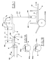
- Figures 1 and 2 show schematically the sequence of a working cycle of the proposed method for transferring articles 5 from a first feeding line 1 to a second receiving line 2, situated at a lower level and downstream of the first one.
- the first line 1 carries the articles 5, arranged in row, toward a pad 3, where stopping means 6 move between two extreme positions Z1, Z2, in which they respectively stop and do not interfere with the first article of the row.
- the second line 2 has, for example, a series of holders, which define holding spaces 20, in which the articles 5 can be introduced and carried to a station, in which they are boxed or undergo other operation, which are not shown.
- the shown articles 5 are heat-formed bowl containers filled with products, not shown, introduced therein previously, and with the top open or closed with a suitable sealing film or similar means.
- the bowl containers 5 have a horizontal edge 50, which can interfere with the edge of the adjacent container; more precisely, the rear edge 50b of the leading container 5 can be situated above the fore edge 50a of the subsequent container ( Figure 1A), or vice-versa ( Figure 1B), in an absolutely casual and out of control way.
- leading container 5 must be picked up from the row in such a way, as not to be hindered by the above mentioned edge overlapping.
- the proposed method includes:
- the articles 5 are moved to a picking up pad 3, provided for technical-operative reasons, which are not concerned by the invention and are easily understood by those skilled in the art.
- the pad 3 is omitted and the first line 1 is operated in suitable way, so as to allow the articles to be picked up directly therefrom, for instance in a position corresponding to the end of the first line.
- the trajectory T1 of the first movement S1 can be ascending or descending, for example straight, or horizontal, as in Figure 1.
- the trajectory T2 of the second movement S2 can be defined by a combination of consecutive straight and/or curved sections.
- an article 5 is placed and released onto the transport surface 21 of the above second line 2 ( Figure 1) at each working cycle, in case only one article 5 is to inserted in each holding space 20 of the second line.
- the proposed method allows also formation of a pile P of articles 5 in each holding space of the second line 2 ( Figure 2).
- the placing and releasing height level of the articles is to be set each time higher with respect to the transport surface 21 of the second line 2, by progressive reduction of the motion extension by which the article 5 is lowered during the third straight vertical movement.
- the maximum extent of the third movement is grater than the maximum height of the pile P.
- the second line 2 is situated.at a lower level with respect to the first line 1.
- the proposed method can be applied even if the line 2 is situated at the same, or at a higher level with respect to the line 1.
- This technical-functional aspect can be obtained by the second movement having the trajectory T2 ascending, so as to raise the article 5 to such a level, as to allow to define, for the third movement S3, a straight vertical downward movement in a range greater than the maximum height of the pile P to be obtained.
- the just described method can be carried out by transferring devices 100 and relative gripping means 90, which have different conformations.
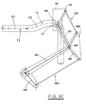
- the transferring device 100 includes a first bar 60, hinged about a pivot 61 and swinging in a vertical plane between two extreme positions, respectively a high position A (Figure 3A) and low position B (Figure 3D), distant form each other by a prefixed angle.
- the bar 60 is operated by a motor M situated, for example, in line with the pivot 61.
- the first bar 60 is one of the longer bars of a first four-bar linkage 160, which has a stationary smaller bar formed by a bracket 64, connecting the positions of the pivot 61 and of a hinge join 65, suitably situated therebelow.
- a second bar 70 is hinged to a free end of the first bar 60 at an hinge joint 66.
- the second bar 70 swings in a vertical plane and is arranged angularly with respect to the first bar 60.
- the remaining shorter bar 68 of the first four-bar linkage 160 extends between the hinge joint 66 and the hinge joint 67.
- the second bar 70 extends from the hinge joint 66 to an hinge joint 71 and forms also one of the longer side of a second four-bar linkage 170, pivoted to the first one at the above hinge joint 66.
- a smaller side 73 of the second four-bar linkage 170 is formed between the hinge joint 66 and an hinge joint 72, and its length is equal to the length of the shorter bar 68 of the first four-bar linkage 160, situated beside.
- the first and the second four-bar linkages 160, 170 are interconnected by means of a plate 180, which stabilizes the mutual position of the respective shorter sides 68, 73, both pivoted to the hinge joint 66.
- the remaining shorter side 75 of the second four-bar linkage 170, parallel to the shorter side 73 thereof, is defined between the hinge joint 71, at the end of the bar 70, and another hinge joint 74.
- the above shorter side 75 is integral with a support 91, to which the picking up means 90 are fastened.
- a roller 80 is rotatably connected to the support 91, and its rotation axis is centered with respect to the hinge joint 71.
- the roller 80 is engaged into a suitably shaped track 81, extending from the first feeding line 1 to the second receiving line 2.
- the track 81 has such a shape as to define the path covered by the support 91, in accordance with the trajectories T1, T2, T3 of the proposed method.
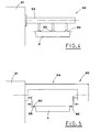
- Figures 4 and 5 show schematically two embodiments of the picking up means 90, connected to the transferring device 100, respectively for articles 5 (or bowl containers) close in their upper part, and for open bowl containers.
- a horizontal arm 92 is cantilevered to the support 91, and a plurality of suction cups 93 extend downwards from the horizontal arm 92.
- the suction cups 93 are set under vacuum condition by known suction means, not shown, to pick up and hold the upper surface of the article 5 (or the sealing film of the bowl container).
- a group 94 equipped with mobile catchers 95, is cantilevered to the support 91.
- the catchers 95 are operated horizontally by known, not shown means, (see arrows in the Figure), to catch and support a bowl container under the outer edge 50.
- Figure 3A shows the transferring device 100 in the configuration corresponding to the described step of the method, in which the leading article 5 is picked up from the picking up pad 3, at the end of the first line 1.
- the first bar 60 is situated in its high position A, while the second bar 70 is suitably arranged, consequently to the engagement of the roller 80 with the track 81, so that the position of the support 91 and of the picking up means 90 is correct to pick up the article 5.
- Figure 3B shows the transferring device 100 in the described step of the method, in which the leading article 5 has been picked up from the pad 3, at the end of the first movement S1, with the trajectory T1 nearly horizontal and straight.
- the motor M is operated in the direction X, to rotate the first bar 60 to its low position B.
- the roller 80 running along the track 81, controls the first trajectory T1 for the coaxial hinge joint 71 and consequently, for the support 91.
- the configuration of the first four-bar linkage 160 is defined by the position of the first bar 60 with respect to the position of the shorter stationary side defined by the bracket 64.
- the configuration of the second four-arm linkage 170 is determined by the interaction of the roller 80, which is in engagement with the track 81 to define the orientation of the second bar 70, and of the plate 180. Therefore, the shorter sides 73, 75 of the second four-bar linkage 170 maintain the same inclination as at the beginning, with an angle unchanged with respect to the shorter sides 64, 68 of the first.four-bar linkage 160.
- the combination of the movements of the first bar 60 and of the four-bar linkages 160, 170, together with the track 81 profile, determine the trajectory of the support 91 movements, and consequently, of the article 5 picked up by the picking up means 90.
- the geometry of the two four-bar linkages 160, 170 is such, as to maintain constant the spatial orientation of the support 91 of the picking up means 90, and consequently, of the article 5 ( Figures 1 and 2).
- management and control means suitably acting on the motor M, can progressively reduce the third movement S3, to place and release the article 5 each time at a higher level, to form a pile P, in accordance with the method.
- the leading article picking up step is not obstructed by the overlapping of the edges, independently from the picking up mode, because it is done with the first movement S1 almost horizontal and straight.
- Another advantage results from the possibility to form, on the second line, a pile of articles, or to introduce correctly an article of considerable height, into the holding space defined by the holders of the second line, due to the third movement S3 having vertical and straight trajectory.
- a further advantage of the proposed method derives from the fact that the article arrangement remains unchanged during its conveying.
- the described transferring device 100 can perfectly perform various step of the method, however alternative constructive solutions are possible, either entirely mechanical, like the proposed one, or with electronic control of the moving axes.
Landscapes
- Engineering & Computer Science (AREA)
- Mechanical Engineering (AREA)
- Specific Conveyance Elements (AREA)
Applications Claiming Priority (2)
| Application Number | Priority Date | Filing Date | Title |
|---|---|---|---|
| ITBO20030112 | 2003-03-04 | ||
| IT000112A ITBO20030112A1 (it) | 2003-03-04 | 2003-03-04 | Metodo per il trasferimento di articoli da una prima linea |
Publications (2)
| Publication Number | Publication Date |
|---|---|
| EP1454855A2 true EP1454855A2 (de) | 2004-09-08 |
| EP1454855A3 EP1454855A3 (de) | 2004-10-27 |
Family
ID=32800654
Family Applications (1)
| Application Number | Title | Priority Date | Filing Date |
|---|---|---|---|
| EP04004468A Withdrawn EP1454855A3 (de) | 2003-03-04 | 2004-02-27 | Verfahren und Vorrichtung zur Übergabe von Artikeln von einer ersten zu einer zweiten, nachgeordneten Förderlinie |
Country Status (3)
| Country | Link |
|---|---|
| US (1) | US20040173437A1 (de) |
| EP (1) | EP1454855A3 (de) |
| IT (1) | ITBO20030112A1 (de) |
Cited By (2)
| Publication number | Priority date | Publication date | Assignee | Title |
|---|---|---|---|---|
| CN106865184A (zh) * | 2017-01-13 | 2017-06-20 | 东莞市圣荣自动化科技有限公司 | 一种汽车自动化生产线的中部部件运送架 |
| US11291861B2 (en) | 2019-03-08 | 2022-04-05 | Mevion Medical Systems, Inc. | Delivery of radiation by column and generating a treatment plan therefor |
Families Citing this family (3)
| Publication number | Priority date | Publication date | Assignee | Title |
|---|---|---|---|---|
| DE102004043332A1 (de) * | 2004-09-08 | 2006-03-09 | Iwk Verpackungstechnik Gmbh | Verfahren zum Umsetzen eines Produktes in einer Verpackungsmaschine und Umsetzvorrichtung zur Durchführung des Verfahrens |
| ITBO20060899A1 (it) * | 2006-12-29 | 2008-06-30 | Marchesini Group Spa | Apparato per il riempimento di tubetti con pile di articoli di forma discoidale, quali compresse |
| CN106586500B (zh) * | 2017-01-13 | 2018-11-23 | 重庆长青球墨铸铁制造有限责任公司 | 一种汽车部件输送用电机提升式输送架 |
Family Cites Families (1)
| Publication number | Priority date | Publication date | Assignee | Title |
|---|---|---|---|---|
| DE4024335A1 (de) * | 1990-07-31 | 1992-02-06 | Hermann Kronseder | Packvorrichtung |
-
2003
- 2003-03-04 IT IT000112A patent/ITBO20030112A1/it unknown
-
2004
- 2004-02-27 EP EP04004468A patent/EP1454855A3/de not_active Withdrawn
- 2004-03-01 US US10/790,281 patent/US20040173437A1/en not_active Abandoned
Cited By (3)
| Publication number | Priority date | Publication date | Assignee | Title |
|---|---|---|---|---|
| CN106865184A (zh) * | 2017-01-13 | 2017-06-20 | 东莞市圣荣自动化科技有限公司 | 一种汽车自动化生产线的中部部件运送架 |
| US11291861B2 (en) | 2019-03-08 | 2022-04-05 | Mevion Medical Systems, Inc. | Delivery of radiation by column and generating a treatment plan therefor |
| US11311746B2 (en) | 2019-03-08 | 2022-04-26 | Mevion Medical Systems, Inc. | Collimator and energy degrader for a particle therapy system |
Also Published As
| Publication number | Publication date |
|---|---|
| EP1454855A3 (de) | 2004-10-27 |
| US20040173437A1 (en) | 2004-09-09 |
| ITBO20030112A1 (it) | 2004-09-05 |
Similar Documents
| Publication | Publication Date | Title |
|---|---|---|
| CA2065172C (en) | Bag handling machine | |
| US20150013277A1 (en) | Method and apparatus for inserting packages into cartons | |
| KR101731582B1 (ko) | 로터리 포장기 | |
| EP1164099B1 (de) | Verfahren und Vorrichtung zum überführen von Blisterverpackungen von einem auf einen anderen Bandförderer | |
| US5056299A (en) | Apparatus for opening and placing bags on a filling hopper | |
| US4612965A (en) | Automatic bag hanging device | |
| CN1106755A (zh) | 袋堆输送装置 | |
| US6220424B1 (en) | Method and apparatus for transferring items from a conveyor | |
| US11396395B2 (en) | Automated bag loading system | |
| CN1899143A (zh) | 成批处理和传送烟草制品的方法和设备 | |
| CN212667813U (zh) | 全自动上袋机 | |
| EP1454855A2 (de) | Verfahren und Vorrichtung zur Übergabe von Artikeln von einer ersten zu einer zweiten, nachgeordneten Förderlinie | |
| US9365309B2 (en) | Preformed bag feeder for packaging machines | |
| US3943687A (en) | Apparatus for taking-up and conveying bags | |
| EP0734949B1 (de) | Vorrichtung zum Bilden von Gruppen von Gegenständen in Kartoniermaschinen oder dergleichen | |
| US3221910A (en) | Bottle-feeding apparatus | |
| US5083411A (en) | Apparatus for unstacking, filling and stacking containers which are the same as each other | |
| WO2002083500A1 (en) | Method and system for placing packages in an outer packaging | |
| CN110742102B (zh) | 一种馄饨全自动生产设备 | |
| US20030019541A1 (en) | Sack filling method and apparatus | |
| EP1770016A1 (de) | Verfahren und Vorrichtung zum Vereinzeln von flach gefalteten, gestapelten Artikeln aus dem Boden eines Magazins | |
| EP1707513B2 (de) | Verfahren und Vorrichtung zur Übergabe von Gegenständen von einem ersten Fördermittel an einem zweiten Fördermittel | |
| US7033129B2 (en) | Method for feeding blanks to a boxing machine | |
| US4648234A (en) | Automatic bag-loading attachment for rotary bag-filling machines | |
| US6048164A (en) | Sticker placement apparatus |
Legal Events
| Date | Code | Title | Description |
|---|---|---|---|
| PUAI | Public reference made under article 153(3) epc to a published international application that has entered the european phase |
Free format text: ORIGINAL CODE: 0009012 |
|
| AK | Designated contracting states |
Kind code of ref document: A2 Designated state(s): AT BE BG CH CY CZ DE DK EE ES FI FR GB GR HU IE IT LI LU MC NL PT RO SE SI SK TR |
|
| AX | Request for extension of the european patent |
Extension state: AL LT LV MK |
|
| PUAL | Search report despatched |
Free format text: ORIGINAL CODE: 0009013 |
|
| AK | Designated contracting states |
Kind code of ref document: A3 Designated state(s): AT BE BG CH CY CZ DE DK EE ES FI FR GB GR HU IE IT LI LU MC NL PT RO SE SI SK TR |
|
| AX | Request for extension of the european patent |
Extension state: AL LT LV MK |
|
| AKX | Designation fees paid | ||
| REG | Reference to a national code |
Ref country code: DE Ref legal event code: 8566 |
|
| STAA | Information on the status of an ep patent application or granted ep patent |
Free format text: STATUS: THE APPLICATION IS DEEMED TO BE WITHDRAWN |
|
| 18D | Application deemed to be withdrawn |
Effective date: 20050428 |