EP1454873A1 - Scherenhubvorrichtung - Google Patents
Scherenhubvorrichtung Download PDFInfo
- Publication number
- EP1454873A1 EP1454873A1 EP03004756A EP03004756A EP1454873A1 EP 1454873 A1 EP1454873 A1 EP 1454873A1 EP 03004756 A EP03004756 A EP 03004756A EP 03004756 A EP03004756 A EP 03004756A EP 1454873 A1 EP1454873 A1 EP 1454873A1
- Authority
- EP
- European Patent Office
- Prior art keywords
- scissor
- lifting device
- scissor lifting
- traction means
- coupling
- Prior art date
- Legal status (The legal status is an assumption and is not a legal conclusion. Google has not performed a legal analysis and makes no representation as to the accuracy of the status listed.)
- Granted
Links
- 230000008878 coupling Effects 0.000 claims abstract description 48
- 238000010168 coupling process Methods 0.000 claims abstract description 48
- 238000005859 coupling reaction Methods 0.000 claims abstract description 48
- 238000004804 winding Methods 0.000 claims description 8
- 230000008859 change Effects 0.000 claims description 4
- 239000000463 material Substances 0.000 claims description 2
- 238000011161 development Methods 0.000 description 3
- 230000002349 favourable effect Effects 0.000 description 2
- 230000007246 mechanism Effects 0.000 description 2
- 230000006978 adaptation Effects 0.000 description 1
- 230000005540 biological transmission Effects 0.000 description 1
- 238000010276 construction Methods 0.000 description 1
- 238000013016 damping Methods 0.000 description 1
- 230000000694 effects Effects 0.000 description 1
- 239000000314 lubricant Substances 0.000 description 1
- 238000000034 method Methods 0.000 description 1
- 230000004048 modification Effects 0.000 description 1
- 238000012986 modification Methods 0.000 description 1
- 230000008569 process Effects 0.000 description 1
- 230000000284 resting effect Effects 0.000 description 1
- 230000007480 spreading Effects 0.000 description 1
- 230000006641 stabilisation Effects 0.000 description 1
- 238000011105 stabilization Methods 0.000 description 1
- 230000001360 synchronised effect Effects 0.000 description 1
- 238000012549 training Methods 0.000 description 1
- 230000007704 transition Effects 0.000 description 1
Images


Classifications
-
- B—PERFORMING OPERATIONS; TRANSPORTING
- B66—HOISTING; LIFTING; HAULING
- B66F—HOISTING, LIFTING, HAULING OR PUSHING, NOT OTHERWISE PROVIDED FOR, e.g. DEVICES WHICH APPLY A LIFTING OR PUSHING FORCE DIRECTLY TO THE SURFACE OF A LOAD
- B66F7/00—Lifting frames, e.g. for lifting vehicles; Platform lifts
- B66F7/06—Lifting frames, e.g. for lifting vehicles; Platform lifts with platforms supported by levers for vertical movement
- B66F7/065—Scissor linkages, i.e. X-configuration
Definitions
- the invention relates to a scissor lifting device with at least two pairs by one Pivot axis connected scissor members, the pivot axis between the respective End sections of the scissor links is arranged, and with a drive for erecting and lowering the scissor members by means of a traction device.
- Such a scissor lifting device is the subject of DE 100 24 075 A1, for example.
- the traction means the distance between the upper or lower ends the scissor links changed.
- the traction means with one end of one of the scissor links and by means of a deflection roller at an upper end of the other scissor link connected to the drive and thus retractable.
- the traction means acts on an expansion body, that in the lowered rest position of the scissor lifting device near the lower one End of a scissor link between this and the overlying upper end of the other Scissor link lies.
- the traction means is not wound up by means of the drive, but has one of them Loop closed end section so as to prevent the traction device from sliding off.
- a disadvantage of such scissor lifting devices is their lifting height of an expansion body is varied so that the lever ratios in the lowered rest position differ significantly from the raised working position.
- the one for change The forces required for the lifting height differ in the two extreme positions by a multiple. In practice, this leads to signs of wear. It will also large drive power required. It is also necessary to move the To influence the spreading body with the help of a complex control such that the lifting speed between the extreme positions is almost constant, at least is not subject to undesirably high fluctuations.
- US Pat. No. 4,858,888 also discloses a scissor lifting device in which the free end of the support arm is guided by an angled guide arm, which is also articulated to the first scissor link.
- the invention has for its object to provide a way to a scissor lifting device of the type mentioned at the outset in such a way that the operations required Drive power is significantly reduced. Furthermore, the scissor lifting device should be low Effort to be adapted to different purposes.
- the scissor lift device has at least one coupling bridge with two by means of a joint pivotably arranged struts, each with one Scissor link are pivotally connected, the coupling bridge a pulley for the traction device defined on the scissor lifting device.
- the coupling bridge is included the pulley, so that by applying the tensile force the distance and thereby at the same time the lifting height can be changed with little effort. Because of this Realizable favorable leverage ratios become the peak load to be applied by the drive, especially when lifting from the lowered rest position, significantly reduced. This also results in significantly less wear, because the deflection the traction device is only subject to very low friction losses. Furthermore, it shows that due to the changed force application an almost constant ratio between the Differential length of the traction device and the difference in lifting height can be realized, which the Control effort is significantly reduced.
- the scissor lift device also allows easy adaptation to different application conditions, by using larger ones Load requirements only the traction device must be replaced. Cumbersome new designs can be avoided in many cases.
- the free end of the traction device can be fixed on the swivel axis.
- a special one practical embodiment of the present invention is also achieved by that the scissor lifting device is arranged on both sides of the pivot axis Has coupling bridge, the first coupling bridge with at least one deflection roller and the second coupling bridge is equipped with a fixation for the traction means. hereby is a considerably more uniform force transmission into the scissor links by the two opposite coupling bridges reached by means of the respective push struts and thereby increases operational safety and, at the same time, stresses individual push struts reduced.
- a particularly advantageous development is also realized in that the pivot axis and the coupling bridges in a common, in particular horizontal, plane are arranged. This achieves a uniform stroke movement and at the same time Fluctuations in the required drive power between the extreme positions of the scissor lifting device reduced.
- the tracks which are in particular guided parallel to one another, could be in a common in particular by the plane determined by the pivot axis.
- the deflection of the traction means takes place even when it is stationary outside the scissor lift device positioned drive for the traction mechanism only in one level.
- the resulting load on the traction device as well as wear and tear are significantly reduced.
- An embodiment of the invention has also proven to be particularly advantageous Scissor lifting device in which the push struts have a matching distance between have the coupling bridge and the respectively associated scissor link. hereby the orientation of the coupling bridge, unlike the principle of parallel program guidance, is unaffected from the room position depending on the lifting height. The path of the Traction means is therefore constant over the entire lifting height.
- the traction means can for example be a plastic or wire rope, a chain or a wedge or Toothed belt must be executed.
- an embodiment is particularly practical which the traction means is designed at least in sections as a webbing.
- the webbing combines high flexibility and tensile strength and also requires no lubricants. Furthermore, the webbing can be used and permitted without disturbing operating noises a flat overall height.
- a particularly versatile embodiment of the invention is also achieved by that the scissor lifting device by means of further paired scissor links is modularly expandable. This allows double or tandem constructions with little effort be realized, which are operated by a single common traction can be. A control effort required for one according to the prior art synchronous movement is therefore no longer necessary. If several traction devices are used, can, according to a further advantageous embodiment, in particular by means of a common drive can be actuated.
- Another particularly promising embodiment of the present invention is achieved in that the two coupling bridges by means of one to adapt to different Lifting heights of continuously variable guide elements connected to each other are.
- This guide element which is in particular telescopic, is limited the relative mobility of the two coupling bridges to one another to only one degree of freedom, so that only the distance between the two coupling bridges is variable. The orientation the coupling bridges are therefore immutable.
- the guide element as a damper or emergency actuator is carried out, in the event of a sudden strain relief, an unintentional lowering to avoid the lifting device.
- a hydraulic cylinder equipped guide element damping Load changes.
- the drive can be arranged spatially separated from the scissor lifting device. However, an embodiment is also particularly compact if the drive is on the coupling bridge in one determined by the joints of the push struts and the swivel axis Level is arranged. Several drives can each be assigned to a coupling bridge and be arranged opposite each other.
- Scissor lift device reached when the drive with a winding drum for the Traction means is connected, which is determined in particular by the number of windings Coil diameter determined as a function of the material thickness of the traction device is that a constant rotation speed of the winding drum leads to a constant change in the Lifting height of the scissor lifting device leads to a uniform one without speed control To realize stroke movement.
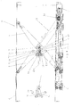
- FIG. 1 shows a scissor lifting device 1 according to the invention in a side view.
- the Scissor lifting device 1 has two arranged in pairs below a lifting level 2 scissor members 4, 5 connected by a pivot axis 3, the pivot axis 3 in the middle between the respective end sections 6, 7 carrying the lifting plane 2, on the other hand, end sections 9, 10 of the scissor members 4 resting on a bottom surface 8, 5 is arranged.
- the scissor lifting device 1 is fixed to the base surface 8 arranged drive 11 equipped, on the winding drum 12 a designed as a webbing Traction means 13 equipped for raising and lowering the scissor members 4, 5 is.
- the scissor lifting device 1 is arranged with two on both sides of the pivot axis 3, parallel, coupling bridges 14, 15 equipped, the first coupling bridge 14 with at least two deflection rollers 16 and the second coupling bridge 15 with one Deflection roller 16 and a fixation 17 for the traction means 13 is equipped, so that the Traction means 13 is guided over one another in a plurality of tracks 18, 19, 20, 21.
- the two coupling bridges 14, 15 are each supported by two identical struts 22, 23 on the Scissor members 4, 5 pivotable.
- the distance a of the coupling bridges 14, 15 is variable, so that the lifting height h can be achieved in the desired manner.
- the coupling bridges 14, 15 by a guide element acting as a damper, in particular realized by a cylinder 24 connected so that load changes do not lead to undesirably high peak loads.
- FIG. 2 shows a detailed view of the scissor lifting device shown in FIG. 1 1 a further traction means 25 guided in a plane parallel to the plane of representation, which is actuated by the common drive 11.
- a further traction means 25 guided in a plane parallel to the plane of representation, which is actuated by the common drive 11.
- course of the tracks 18, 19, 20, 21 of the traction means 13 wraps around the further train medium 25 the pulleys 16 in opposite directions.
- the tensile force F increases Traction means 13, 25 initiated moments against each other.
- FIG. 3 is an enlarged detailed view of the scissor lifting device shown in FIG. 1 1 in a lowered position in which the coupling bridges 14, 15 are spaced apart A have.
- the traction means 13 is fixed on the second coupling bridge 15 Guide roller pair 26 out.
- By deflecting the traction means 13 on two guide rollers 16 of the first coupling bridge 14 and a deflection roller 16 of the second coupling bridge 15 and the fixation 17 of the traction means 13 to the second coupling bridge 15 becomes one Multiplication of the transferable force achieved, so that even large lifting forces with one comparatively little effort can be realized.
- the necessary ones give way Tractive forces in the lowered position shown only slightly from that shown in Figure 1 Operating position, so that with a constant pulling movement of the traction means 13 a uniform lifting movement is achieved.
- FIG. 4 shows the scissor lifting device 1 in a modified form with two below the lifting level 2 by the pivot axis 3 connected scissor members 4, 5 with the the bottom surface 8 of the stationary drive 11, on the winding drum 12 the traction means 13 is fixed for raising and lowering the scissor members 4, 5.
- the scissor lift device 1 has only a single one to the side of the pivot axis 3 in this embodiment arranged coupling bridge 14, which carries a plurality of deflection rollers 16.
- the fixation 17 for that Traction means 13 is connected to the pivot axis 3 in a common vertical plane, so that the traction means 13 are guided one above the other in several tracks 18, 19, 20, 21 is.
- the coupling bridge 14 is supported by two identical struts 22, 23 on the Scissor members 4, 5 pivotable. By introducing a tensile force F by means of The distance a of the coupling bridge 14 from the swivel axis 3 can be changed by means of traction means 13, so that the lifting height h can be set as desired.
- the coupling bridge 14 is connected by the guide element 24 to the pivot axis 3, so that a substantially vertical alignment of the coupling bridge 14 with different Lifting heights h is guaranteed.
Landscapes
- Life Sciences & Earth Sciences (AREA)
- Engineering & Computer Science (AREA)
- Geology (AREA)
- Mechanical Engineering (AREA)
- Structural Engineering (AREA)
- Forklifts And Lifting Vehicles (AREA)
- Load-Engaging Elements For Cranes (AREA)
- Sanitary Device For Flush Toilet (AREA)
- Glass Compositions (AREA)
- Insulated Conductors (AREA)
- Types And Forms Of Lifts (AREA)
Abstract
Description
- Fig.1
- eine Seitenansicht einer erfindungsgemäßen Scherenhubvorrichtung;
- Fig.2
- eine Detailansicht der in Figur 1 gezeigten Scherenhubvorrichtung;
- Fig.3
- eine vergrößerte Detailansicht der in Figur 1 gezeigten Scherenhubvorrichtung in einer abgesenkten Position;
- Fig. 4
- eine abgewandelte Ausführungsform der in Figur 1 gezeigten Scherenhubvorrichtung.
Claims (14)
- Scherenhubvorrichtung (1) mit zumindest zwei paarweise durch eine Schwenkachse (3) verbundenen Scherengliedern (4, 5), wobei die Schwenkachse (3) zwischen den jeweiligen Endabschnitten (6, 7, 8, 9) der Scherenglieder (4, 5) angeordnet ist, und mit einem Antrieb (11) zum Aufrichten und Absenken der Scherenglieder (4, 5) mittels eines Zugmittels (13, 25), gekennzeichnet durch zumindest eine Koppelbrücke (14, 15) mit zwei schwenkbeweglich angeordneten Schubstreben (22, 23), die mit jeweils einem Scherenglied (4, 5) schwenkbeweglich verbunden sind, wobei die Koppelbrücke (14, 15) eine Umlenkrolle (16) für das an der Scherenhubvorrichtung (1) festgelegte Zugmittel (13, 25) trägt.
- Scherenhubvorrichtung (1) nach Anspruch 1, dadurch gekennzeichnet, dass die Scherenhubvorrichtung (1) zwei beiderseits der Schwenkachse (3) angeordnete Koppelbrücken (14, 15) aufweist, wobei die erste Koppelbrücke (14) mit zumindest einer Umlenkrolle (16) und die zweite Koppelbrücke (15) mit einer Fixierung (17) für das Zugmittel (13, 25) ausgestattet ist.
- Scherenhubvorrichtung (1) nach Anspruch 2, dadurch gekennzeichnet, dass die Schwenkachse (3) und die Koppelbrücken (14, 15) in einer gemeinsamen, insbesondere horizontalen, Ebene angeordnet sind.
- Scherenhubvorrichtung (1) nach den Ansprüchen 2 oder 3, dadurch gekennzeichnet, dass das Zugmittel (13, 25) zwischen den beiden Koppelbrücken (14, 15) mittels mehrerer, an den beiden Koppelbrücken (14, 15) angeordneten Umlenkrollen (16) in mehreren Bahnen (18, 19, 20, 21) geführt ist.
- Scherenhubvorrichtung (1) nach Anspruch 4, dadurch gekennzeichnet, dass die Bahnen (18, 19, 20, 21) des Zugmittels (13, 25) übereinander angeordnet sind.
- Scherenhubvorrichtung (1) nach zumindest einem der vorhergehenden Ansprüche, dadurch gekennzeichnet, dass die Schubstreben (22, 23) einen übereinstimmenden Abstand zwischen der Koppelbrücke (14, 15) und dem jeweils zugeordneten Scherenglied (4, 5) aufweisen.
- Scherenhubvorrichtung (1) nach zumindest einem der vorhergehenden Ansprüche, dadurch gekennzeichnet, dass mehrere parallel zueinander angeordnete Zugmittel (13, 25) die Umlenkrolle (16) gegenläufig umschlingen.
- Scherenhubvorrichtung (1) nach zumindest einem der vorhergehenden Ansprüche, dadurch gekennzeichnet, dass das Zugmittel (13, 25) zumindest abschnittsweise als ein Gurtband ausgeführt ist.
- Scherenhubvorrichtung (1) nach zumindest einem der vorhergehenden Ansprüche, dadurch gekennzeichnet, dass die Scherenhubvorrichtung (1) mittels weiterer paarweise angeordneter Scherenglieder (4, 5) modular erweiterbar ist.
- Scherenhubvorrichtung (1) nach zumindest einem der vorhergehenden Ansprüche, dadurch gekennzeichnet, dass die Scherenhubvorrichtung (1) mehrere insbesondere mittels eines gemeinsamen Antriebes (11) betätigbare Zugmittel (13, 25) aufweist.
- Scherenhubvorrichtung (1) nach zumindest einem der vorhergehenden Ansprüche, dadurch gekennzeichnet, dass die beiden Koppelbrücken (14, 15) mittels eines zur Anpassung an unterschiedliche Hubhöhen (h) stufenlos längenveränderlichen Führungselementes (24) miteinander verbunden sind.
- Scherenhubvorrichtung (1) nach Anspruch 11, dadurch gekennzeichnet, dass das Führungselement (24) als Dämpfer und/oder Notstellglied ausgeführt ist
- Scherenhubvorrichtung (1) nach zumindest einem der vorhergehenden Ansprüche, dadurch gekennzeichnet, dass der Antrieb (11) an der Koppelbrücke (14, 15) angeordnet ist.
- Scherenhubvorrichtung (1) nach zumindest einem der vorhergehenden Ansprüche, dadurch gekennzeichnet, dass der Antrieb (11) mit einer Wickeltrommel (12) für das Zugmittel (13, 25) verbunden ist, deren Wickeldurchmesser in Abhängigkeit von der Materialsstärke des Zugmittels (13, 25) derart bestimmt ist, dass eine konstante Drehzahl der Wickeltrommel (12) zu einer konstanten Änderung der Hubhöhe (h) der Scherenhubvorrichtung (1) führt.
Priority Applications (5)
| Application Number | Priority Date | Filing Date | Title |
|---|---|---|---|
| EP03004756A EP1454873B1 (de) | 2003-03-04 | 2003-03-04 | Scherenhubvorrichtung |
| DE50305742T DE50305742D1 (de) | 2003-03-04 | 2003-03-04 | Scherenhubvorrichtung |
| AT03004756T ATE346011T1 (de) | 2003-03-04 | 2003-03-04 | Scherenhubvorrichtung |
| US10/792,283 US7213686B2 (en) | 2003-03-04 | 2004-03-04 | Scissor lift mechanism |
| CNB2004100074726A CN1315717C (zh) | 2003-03-04 | 2004-03-04 | 剪刀式起重设备 |
Applications Claiming Priority (1)
| Application Number | Priority Date | Filing Date | Title |
|---|---|---|---|
| EP03004756A EP1454873B1 (de) | 2003-03-04 | 2003-03-04 | Scherenhubvorrichtung |
Publications (2)
| Publication Number | Publication Date |
|---|---|
| EP1454873A1 true EP1454873A1 (de) | 2004-09-08 |
| EP1454873B1 EP1454873B1 (de) | 2006-11-22 |
Family
ID=32798766
Family Applications (1)
| Application Number | Title | Priority Date | Filing Date |
|---|---|---|---|
| EP03004756A Expired - Lifetime EP1454873B1 (de) | 2003-03-04 | 2003-03-04 | Scherenhubvorrichtung |
Country Status (5)
| Country | Link |
|---|---|
| US (1) | US7213686B2 (de) |
| EP (1) | EP1454873B1 (de) |
| CN (1) | CN1315717C (de) |
| AT (1) | ATE346011T1 (de) |
| DE (1) | DE50305742D1 (de) |
Cited By (3)
| Publication number | Priority date | Publication date | Assignee | Title |
|---|---|---|---|---|
| DE102006006467A1 (de) * | 2006-02-10 | 2007-08-16 | Grundei Hebetische Verladetechnik Gmbh | Scherenhubtisch |
| EP2019076A1 (de) * | 2007-07-27 | 2009-01-28 | Ludwig Göcke | Scherenhubvorrichtung |
| DE102023109474A1 (de) | 2023-04-14 | 2024-10-17 | Pro Hub Hebetechnik Gmbh | Vorrichtung zum Anheben von Lasten und Verfahren zum gleichförmigen Anheben oder Absenken von Lasten |
Families Citing this family (29)
| Publication number | Priority date | Publication date | Assignee | Title |
|---|---|---|---|---|
| US20060037518A1 (en) * | 2004-08-17 | 2006-02-23 | Adelardo Lopez Alba | Power-operated scissor lift table |
| US7120228B2 (en) * | 2004-09-21 | 2006-10-10 | Jordan Valley Applied Radiation Ltd. | Combined X-ray reflectometer and diffractometer |
| US8469152B2 (en) * | 2007-09-25 | 2013-06-25 | Hunter Engineering Company | Methods and systems for multi-capacity vehicle lift system |
| WO2010129311A1 (en) * | 2009-05-07 | 2010-11-11 | Vehicle Service Group, Llc | Multi-link automotive alignment lift |
| US8662477B2 (en) * | 2009-12-16 | 2014-03-04 | Herkules Equipment Corporation | Belt-driven transportation system |
| US8714524B2 (en) * | 2009-12-16 | 2014-05-06 | Herkules Equipment Corporation | Belt-driven transportation system |
| US8243878B2 (en) | 2010-01-07 | 2012-08-14 | Jordan Valley Semiconductors Ltd. | High-resolution X-ray diffraction measurement with enhanced sensitivity |
| US8733508B2 (en) | 2010-04-02 | 2014-05-27 | Herkules Equipment Corporation | Scissor lift assembly |
| RU2535772C2 (ru) * | 2010-07-05 | 2014-12-20 | Коне Корпорейшн | Компенсирующее устройство и лифт |
| US8687766B2 (en) | 2010-07-13 | 2014-04-01 | Jordan Valley Semiconductors Ltd. | Enhancing accuracy of fast high-resolution X-ray diffractometry |
| US8437450B2 (en) | 2010-12-02 | 2013-05-07 | Jordan Valley Semiconductors Ltd. | Fast measurement of X-ray diffraction from tilted layers |
| US8827246B2 (en) * | 2011-03-25 | 2014-09-09 | Parking Source Llc | Scissor lift |
| US8781070B2 (en) | 2011-08-11 | 2014-07-15 | Jordan Valley Semiconductors Ltd. | Detection of wafer-edge defects |
| DE202012003063U1 (de) | 2012-03-27 | 2012-04-11 | Rofa Gmbh | Scherenhubtisch |
| DE102012006028A1 (de) | 2012-03-27 | 2013-10-02 | Rofa Industrial Automation Ag | Scherenhubtisch |
| DE202013100340U1 (de) | 2012-07-13 | 2013-02-08 | Rofa Industrial Automation Ag | Hubtischsteuerung |
| US9296596B2 (en) | 2012-10-15 | 2016-03-29 | Cameron Lanning Cormack | Hybrid wedge jack/scissor lift lifting apparatus and method of operation thereof |
| CN103183294B (zh) * | 2012-11-14 | 2015-04-22 | 湖北华昌达智能装备股份有限公司 | 皮带张紧结构及应用该皮带张紧结构的剪叉升降设备 |
| US9422142B2 (en) | 2013-08-01 | 2016-08-23 | Herkules Equipment Corporation | Scissor-type lift assembly |
| US9726624B2 (en) | 2014-06-18 | 2017-08-08 | Bruker Jv Israel Ltd. | Using multiple sources/detectors for high-throughput X-ray topography measurement |
| US10227222B2 (en) | 2015-07-31 | 2019-03-12 | Vehicle Service Group, Llc | Precast concrete pit |
| US10246313B2 (en) | 2015-07-31 | 2019-04-02 | Vehicle Service Group, Llc | Precast concrete pit |
| US9961989B2 (en) | 2016-03-07 | 2018-05-08 | Marc Stefan Witt | Radial scissor lift table and method |
| US10377611B2 (en) | 2016-10-28 | 2019-08-13 | Advance Lifts, Inc. | Scissors lift with height sensor system |
| EP3476792A1 (de) | 2017-10-25 | 2019-05-01 | Flexlift Hubgeräte GmbH | Scherenhubtisch |
| CN112874306A (zh) * | 2019-11-29 | 2021-06-01 | 比亚迪股份有限公司 | 车辆供电装置 |
| DE102021206534A1 (de) | 2021-06-24 | 2022-12-29 | Robert Bosch Gesellschaft mit beschränkter Haftung | Hubquereinheit |
| DE102021207141B3 (de) * | 2021-07-07 | 2022-12-29 | Siemens Healthcare Gmbh | Patientenlagerungstisch |
| DE102021209083B4 (de) * | 2021-08-18 | 2023-06-07 | Siemens Healthcare Gmbh | Patientenlagerungstisch |
Citations (4)
| Publication number | Priority date | Publication date | Assignee | Title |
|---|---|---|---|---|
| US3785462A (en) * | 1972-06-23 | 1974-01-15 | Applied Radiation Corp | Scissor lift and drive mechanism therefor |
| DE3502641A1 (de) * | 1985-01-26 | 1986-07-31 | Mannesmann AG, 4000 Düsseldorf | Scherenhubvorrichtung |
| DE9108825U1 (de) * | 1991-02-28 | 1991-11-14 | Langewellpott, Ernst, 4992 Espelkamp | Scherenhubtisch |
| WO1999062813A1 (en) * | 1998-05-20 | 1999-12-09 | Hans Balle Christensen | Lifting mechanism |
Family Cites Families (8)
| Publication number | Priority date | Publication date | Assignee | Title |
|---|---|---|---|---|
| DE8229071U1 (de) * | 1982-10-16 | 1983-06-23 | Flexlift Hubgeräte GmbH, 4800 Bielefeld | Hubvorrichtung |
| US4858888A (en) * | 1988-07-11 | 1989-08-22 | Onelio Cruz | Platform lifting mechanism |
| US4984774A (en) * | 1988-11-25 | 1991-01-15 | Picker International, Inc. | Patient support couch assembly |
| DE29803330U1 (de) | 1998-02-25 | 1998-05-07 | Langewellpott, Eva-Maria, 32339 Espelkamp | Hubvorrichtung |
| DE19921435A1 (de) * | 1999-05-08 | 2000-11-16 | Heckert Gmbh | Scherenhubtisch |
| DE10024075A1 (de) | 2000-05-17 | 2001-11-29 | Gotthard Heide | Scherenhubvorrichtung |
| US6516478B2 (en) * | 2001-05-31 | 2003-02-11 | Health & Technology, Inc. | Adjustable height bed |
| US20030047388A1 (en) * | 2001-08-30 | 2003-03-13 | Faitel William M. | Scissors lifter drive apparatus |
-
2003
- 2003-03-04 AT AT03004756T patent/ATE346011T1/de active
- 2003-03-04 EP EP03004756A patent/EP1454873B1/de not_active Expired - Lifetime
- 2003-03-04 DE DE50305742T patent/DE50305742D1/de not_active Expired - Lifetime
-
2004
- 2004-03-04 CN CNB2004100074726A patent/CN1315717C/zh not_active Expired - Lifetime
- 2004-03-04 US US10/792,283 patent/US7213686B2/en not_active Expired - Lifetime
Patent Citations (4)
| Publication number | Priority date | Publication date | Assignee | Title |
|---|---|---|---|---|
| US3785462A (en) * | 1972-06-23 | 1974-01-15 | Applied Radiation Corp | Scissor lift and drive mechanism therefor |
| DE3502641A1 (de) * | 1985-01-26 | 1986-07-31 | Mannesmann AG, 4000 Düsseldorf | Scherenhubvorrichtung |
| DE9108825U1 (de) * | 1991-02-28 | 1991-11-14 | Langewellpott, Ernst, 4992 Espelkamp | Scherenhubtisch |
| WO1999062813A1 (en) * | 1998-05-20 | 1999-12-09 | Hans Balle Christensen | Lifting mechanism |
Cited By (5)
| Publication number | Priority date | Publication date | Assignee | Title |
|---|---|---|---|---|
| DE102006006467A1 (de) * | 2006-02-10 | 2007-08-16 | Grundei Hebetische Verladetechnik Gmbh | Scherenhubtisch |
| DE102006006467B4 (de) * | 2006-02-10 | 2008-09-11 | Grundei Hebetische Verladetechnik Gmbh | Scherenhubtisch |
| EP2019076A1 (de) * | 2007-07-27 | 2009-01-28 | Ludwig Göcke | Scherenhubvorrichtung |
| DE102023109474A1 (de) | 2023-04-14 | 2024-10-17 | Pro Hub Hebetechnik Gmbh | Vorrichtung zum Anheben von Lasten und Verfahren zum gleichförmigen Anheben oder Absenken von Lasten |
| DE102023109474B4 (de) | 2023-04-14 | 2024-11-21 | Pro Hub Hebetechnik Gmbh | Vorrichtung zum Anheben von Lasten und Verfahren zum gleichförmigen Anheben oder Absenken von Lasten |
Also Published As
| Publication number | Publication date |
|---|---|
| US20040251453A1 (en) | 2004-12-16 |
| US7213686B2 (en) | 2007-05-08 |
| CN1315717C (zh) | 2007-05-16 |
| EP1454873B1 (de) | 2006-11-22 |
| CN1526634A (zh) | 2004-09-08 |
| DE50305742D1 (de) | 2007-01-04 |
| ATE346011T1 (de) | 2006-12-15 |
Similar Documents
| Publication | Publication Date | Title |
|---|---|---|
| EP1454873B1 (de) | Scherenhubvorrichtung | |
| DE69607502T2 (de) | Energieführungskette und Kettenträgervorrichtung | |
| DE69000289T2 (de) | Kran mit anhebbarem ausleger und mit einer ausleger-rueckstossvorrichtung. | |
| EP3476791A1 (de) | Transporteinrichtung für einen kran | |
| EP3668810B1 (de) | Aufzugsystem | |
| DE2457864C2 (de) | Laufkatzenkran | |
| DE1929305C3 (de) | Rampe zur abwechselnden Verbindung einer Zufahrt mit mehreren, übereinander angeordneten Stockwerkböden einer Garage od.dgl | |
| DE10053690B4 (de) | Presse mit Linearschlitten | |
| EP2064145A1 (de) | Scherenhubtisch | |
| EP2019076A1 (de) | Scherenhubvorrichtung | |
| DE20216478U1 (de) | Durch Seile gesteuerter Hubtisch | |
| DE1952478A1 (de) | Automatische Riemenspannvorrichtung | |
| EP3966409B1 (de) | Vorrichtung zum abstellen von gegenständen mit horizontal orientiertem antrieb | |
| DE10113561B4 (de) | Vorschubvorrichtung für eine Ramm- und/oder Bohrvorrichtung | |
| EP1375410A1 (de) | Scherenhubtisch | |
| EP1190981B1 (de) | Scherenhubtisch | |
| EP0363939B1 (de) | Getriebe zum Umsetzen einer translatorischen Bewegung in eine Drehbewegung und umgekehrt | |
| DE102021207141B3 (de) | Patientenlagerungstisch | |
| CH662397A5 (de) | Klemmvorrichtung fuer seile oder dergleichen. | |
| EP3922592B1 (de) | Scherenhubtisch | |
| EP1661490B1 (de) | Scheren-Hubtisch | |
| EP4091971B1 (de) | Vorrichtung zum stabilisieren von teleskopscheren mit mehreren zugmitteln | |
| DE10066404B4 (de) | Scherenhubtisch | |
| DE20316700U1 (de) | Scherenhubtisch | |
| EP1161907A1 (de) | Vorrichtung zum Verstellen eines schwenkbaren Abschnitts an einem Sitz-oder Liegemöbel |
Legal Events
| Date | Code | Title | Description |
|---|---|---|---|
| PUAI | Public reference made under article 153(3) epc to a published international application that has entered the european phase |
Free format text: ORIGINAL CODE: 0009012 |
|
| AK | Designated contracting states |
Kind code of ref document: A1 Designated state(s): AT BE BG CH CY CZ DE DK EE ES FI FR GB GR HU IE IT LI LU MC NL PT RO SE SI SK TR |
|
| AX | Request for extension of the european patent |
Extension state: AL LT LV MK |
|
| 17P | Request for examination filed |
Effective date: 20041124 |
|
| AKX | Designation fees paid |
Designated state(s): AT DE FR GB |
|
| GRAP | Despatch of communication of intention to grant a patent |
Free format text: ORIGINAL CODE: EPIDOSNIGR1 |
|
| GRAS | Grant fee paid |
Free format text: ORIGINAL CODE: EPIDOSNIGR3 |
|
| GRAA | (expected) grant |
Free format text: ORIGINAL CODE: 0009210 |
|
| AK | Designated contracting states |
Kind code of ref document: B1 Designated state(s): AT DE FR GB |
|
| REG | Reference to a national code |
Ref country code: GB Ref legal event code: FG4D Free format text: NOT ENGLISH |
|
| REF | Corresponds to: |
Ref document number: 50305742 Country of ref document: DE Date of ref document: 20070104 Kind code of ref document: P |
|
| GBT | Gb: translation of ep patent filed (gb section 77(6)(a)/1977) |
Effective date: 20070110 |
|
| ET | Fr: translation filed | ||
| PLBE | No opposition filed within time limit |
Free format text: ORIGINAL CODE: 0009261 |
|
| STAA | Information on the status of an ep patent application or granted ep patent |
Free format text: STATUS: NO OPPOSITION FILED WITHIN TIME LIMIT |
|
| 26N | No opposition filed |
Effective date: 20070823 |
|
| REG | Reference to a national code |
Ref country code: FR Ref legal event code: PLFP Year of fee payment: 14 |
|
| REG | Reference to a national code |
Ref country code: FR Ref legal event code: PLFP Year of fee payment: 15 |
|
| REG | Reference to a national code |
Ref country code: FR Ref legal event code: PLFP Year of fee payment: 16 |
|
| PGFP | Annual fee paid to national office [announced via postgrant information from national office to epo] |
Ref country code: GB Payment date: 20220324 Year of fee payment: 20 Ref country code: AT Payment date: 20220318 Year of fee payment: 20 |
|
| PGFP | Annual fee paid to national office [announced via postgrant information from national office to epo] |
Ref country code: FR Payment date: 20220323 Year of fee payment: 20 |
|
| PGFP | Annual fee paid to national office [announced via postgrant information from national office to epo] |
Ref country code: DE Payment date: 20220406 Year of fee payment: 20 |
|
| REG | Reference to a national code |
Ref country code: DE Ref legal event code: R071 Ref document number: 50305742 Country of ref document: DE |
|
| REG | Reference to a national code |
Ref country code: GB Ref legal event code: PE20 Expiry date: 20230303 |
|
| REG | Reference to a national code |
Ref country code: AT Ref legal event code: MK07 Ref document number: 346011 Country of ref document: AT Kind code of ref document: T Effective date: 20230304 |
|
| PG25 | Lapsed in a contracting state [announced via postgrant information from national office to epo] |
Ref country code: GB Free format text: LAPSE BECAUSE OF EXPIRATION OF PROTECTION Effective date: 20230303 |