EP1454876B1 - Dispositif de stockage de hydrogène - Google Patents
Dispositif de stockage de hydrogène Download PDFInfo
- Publication number
- EP1454876B1 EP1454876B1 EP04003367.2A EP04003367A EP1454876B1 EP 1454876 B1 EP1454876 B1 EP 1454876B1 EP 04003367 A EP04003367 A EP 04003367A EP 1454876 B1 EP1454876 B1 EP 1454876B1
- Authority
- EP
- European Patent Office
- Prior art keywords
- hydrogen storage
- storage apparatus
- cartridge
- hydrogen
- cartridges
- Prior art date
- Legal status (The legal status is an assumption and is not a legal conclusion. Google has not performed a legal analysis and makes no representation as to the accuracy of the status listed.)
- Expired - Lifetime
Links
Images

Classifications
-
- F—MECHANICAL ENGINEERING; LIGHTING; HEATING; WEAPONS; BLASTING
- F17—STORING OR DISTRIBUTING GASES OR LIQUIDS
- F17C—VESSELS FOR CONTAINING OR STORING COMPRESSED, LIQUEFIED OR SOLIDIFIED GASES; FIXED-CAPACITY GAS-HOLDERS; FILLING VESSELS WITH, OR DISCHARGING FROM VESSELS, COMPRESSED, LIQUEFIED, OR SOLIDIFIED GASES
- F17C11/00—Use of gas-solvents or gas-sorbents in vessels
- F17C11/005—Use of gas-solvents or gas-sorbents in vessels for hydrogen
-
- F—MECHANICAL ENGINEERING; LIGHTING; HEATING; WEAPONS; BLASTING
- F17—STORING OR DISTRIBUTING GASES OR LIQUIDS
- F17C—VESSELS FOR CONTAINING OR STORING COMPRESSED, LIQUEFIED OR SOLIDIFIED GASES; FIXED-CAPACITY GAS-HOLDERS; FILLING VESSELS WITH, OR DISCHARGING FROM VESSELS, COMPRESSED, LIQUEFIED, OR SOLIDIFIED GASES
- F17C11/00—Use of gas-solvents or gas-sorbents in vessels
-
- C—CHEMISTRY; METALLURGY
- C01—INORGANIC CHEMISTRY
- C01B—NON-METALLIC ELEMENTS; COMPOUNDS THEREOF; METALLOIDS OR COMPOUNDS THEREOF NOT COVERED BY SUBCLASS C01C
- C01B3/00—Hydrogen; Gaseous mixtures containing hydrogen; Separation of hydrogen from mixtures containing it; Purification of hydrogen; Reversible storage of hydrogen
- C01B3/0005—Reversible storage of hydrogen, e.g. by hydrogen getters or electrodes
-
- F—MECHANICAL ENGINEERING; LIGHTING; HEATING; WEAPONS; BLASTING
- F17—STORING OR DISTRIBUTING GASES OR LIQUIDS
- F17C—VESSELS FOR CONTAINING OR STORING COMPRESSED, LIQUEFIED OR SOLIDIFIED GASES; FIXED-CAPACITY GAS-HOLDERS; FILLING VESSELS WITH, OR DISCHARGING FROM VESSELS, COMPRESSED, LIQUEFIED, OR SOLIDIFIED GASES
- F17C2201/00—Vessel construction, in particular geometry, arrangement or size
- F17C2201/01—Shape
- F17C2201/0147—Shape complex
- F17C2201/0166—Shape complex divided in several chambers
-
- F—MECHANICAL ENGINEERING; LIGHTING; HEATING; WEAPONS; BLASTING
- F17—STORING OR DISTRIBUTING GASES OR LIQUIDS
- F17C—VESSELS FOR CONTAINING OR STORING COMPRESSED, LIQUEFIED OR SOLIDIFIED GASES; FIXED-CAPACITY GAS-HOLDERS; FILLING VESSELS WITH, OR DISCHARGING FROM VESSELS, COMPRESSED, LIQUEFIED, OR SOLIDIFIED GASES
- F17C2203/00—Vessel construction, in particular walls or details thereof
- F17C2203/06—Materials for walls or layers thereof; Properties or structures of walls or their materials
- F17C2203/0634—Materials for walls or layers thereof
- F17C2203/0636—Metals
-
- F—MECHANICAL ENGINEERING; LIGHTING; HEATING; WEAPONS; BLASTING
- F17—STORING OR DISTRIBUTING GASES OR LIQUIDS
- F17C—VESSELS FOR CONTAINING OR STORING COMPRESSED, LIQUEFIED OR SOLIDIFIED GASES; FIXED-CAPACITY GAS-HOLDERS; FILLING VESSELS WITH, OR DISCHARGING FROM VESSELS, COMPRESSED, LIQUEFIED, OR SOLIDIFIED GASES
- F17C2221/00—Handled fluid, in particular type of fluid
- F17C2221/01—Pure fluids
- F17C2221/012—Hydrogen
-
- Y—GENERAL TAGGING OF NEW TECHNOLOGICAL DEVELOPMENTS; GENERAL TAGGING OF CROSS-SECTIONAL TECHNOLOGIES SPANNING OVER SEVERAL SECTIONS OF THE IPC; TECHNICAL SUBJECTS COVERED BY FORMER USPC CROSS-REFERENCE ART COLLECTIONS [XRACs] AND DIGESTS
- Y02—TECHNOLOGIES OR APPLICATIONS FOR MITIGATION OR ADAPTATION AGAINST CLIMATE CHANGE
- Y02E—REDUCTION OF GREENHOUSE GAS [GHG] EMISSIONS, RELATED TO ENERGY GENERATION, TRANSMISSION OR DISTRIBUTION
- Y02E60/00—Enabling technologies; Technologies with a potential or indirect contribution to GHG emissions mitigation
- Y02E60/30—Hydrogen technology
- Y02E60/32—Hydrogen storage
Definitions
- the invention relates to a hydrogen storage in the form of a metal hydride storage.
- Such memories are state of the art, it is in this context DE 35 02 311 A1 referenced, in which such a memory is described in detail. It consists essentially of a typically made of steel for hydrogen gas-tight pressure vessel which is filled with metal hydride, in the crystal lattice hydrogen is storable. Since the metal hydride expands to a considerable extent during the storage of hydrogen and contracts again after it has been dispensed, it is necessary, in order to avoid a local overstretching of the pressure vessel, to distribute and hold the metal hydride as uniformly as possible over the space of the pressure vessel. For this purpose, metal containers are provided, which are cup-shaped and closed with a lid.
- metal hydride filled metal containers are formed of a hydrogen gas permeable container and stacked within the pressure vessel.
- a centrally arranged to the pressure vessel axis filling and removal tube is provided, which is also permeable to hydrogen gas and consists of sintered material. This filling and withdrawal tube passes through the cassettes in the middle, which are closed to the tube with a wall.
- the metal hydride decomposes upon incorporation of hydrogen into powdery dust. Due to the strong elongation is not reliably ensured even when attaching a lid, the parts of the powder push up the lid and / or infiltrate and so also enters the gap area between the pressure vessel and cassettes metal hydride. Then, however, hydrogen is deposited in this area, which can lead to undesirable locally increased tension on the pressure vessel shell, whereby the pressure vessel could be permanently damaged.
- the invention has the object, a hydrogen storage of hydrogen storage in such a way that the aforementioned disadvantages are avoided, in particular the metal hydride even when stretched within the cassettes located in the pressure vessel remains and the best possible heat conduction takes place within the pressure vessel.
- the basic idea of the present invention is to weld the metal hydride-filled cassettes at least partially to each other at least on the side facing the pressure vessel, that is, on its outer circumference.
- the heat exchange between the cassettes is substantially improved, since the entire jacket of the cassettes is connected to one another in a heat-conducting manner by the circumferential welds. It is therefore also ensured a good heat conduction at the points that do not rest thermally conductive on the pressure vessel.
- it is ensured by the cohesive connection that even when expanding the metal hydride no material enters the area between the cassette and the pressure vessel wall.
- the metal hydride powder is held much more reliably than in the prior art locally within the pressure vessel, ie in the cassettes.
- Another significant advantage of the solution according to the invention is that the entire pressure vessel contents, so all cassettes including metal hydride outside the pressure vessel, where they are easily accessible and controllable, assembled and connected by welding, so that then formed by the cassettes cylinder block as a whole can be used in the still open pressure vessel.
- the assembly is thereby considerably simplified and improved.
- the cassettes are cup-shaped and stacked within the pressure body so that the bottom of a cassette forms the lid of the adjacent cassette.
- adjacent cassettes are preferably welded together over the entire circumference, so that the cassette side forms a closed wall to the pressure vessel wall, on the one hand prevents the escape of metal hydride in this area and on the other hand connects all cassettes heat-conducting together. Since at least in sections, but preferably over the entire surface of the thus formed coat of cassettes rests against the inside of the pressure vessel, there is also a very good heat conduction between the pressure vessel and cassettes and thus also the metal hydride stored therein.
- the loading and discharge with hydrogen is advantageously carried out via a centrally arranged and permeable to hydrogen filling and removal tube, which is preferably arranged coaxially within the pressure vessel and penetrates all cassettes.
- the cassettes can have a wall towards the tube, in order to ensure a uniform contact of the metal hydride in this direction. In the latter case, however, care must be taken that no metal hydride escapes through the central bore prior to assembly.
- This is advantageously carried out in that the metal hydride is not filled in powder, granular or pellets, but as a complete ingot, which then automatically decomposes into powder after the first loading with hydrogen.
- the bottom of a cassette is stepped, in such a way that the cassette can be incorporated positively into the open side of the adjacent cassette.
- Such a paragraph facilitates assembly and also offers in addition to the material connection even form fit, so additional security.
- the heat conduction between Floor and cassette sheath, in particular the subsequent cassette improved.
- This circumferential groove can then serve to receive the weld, so that the weld terminates flush with the outer jacket of the cassettes.
- the graded inner part provides a weld bed security, which reliably prevents sagging of the weld into the container interior and also reduces the effect of heat on the metal hydride during welding.
- the cassettes can be made as deep-drawn parts, for example made of aluminum or a good heat-conducting and deformable light metal alloy or other alloy. However, they can also be drawn as shaped parts, for example, from aluminum sheets or else machined or machined.
- the production of the outside in its thickness increasing bottom of a cassette can be simplified in that the cassette is first made with a bottom of constant thickness and then an insert, for example in the form of an aluminum ring is placed on the bottom of the cassette, which increases in thickness from the inside out , The loose system is sufficient here, because due to the elongation of the metal hydride during the first loading a sufficiently high contact pressure is ensured, which ensures a good heat transfer for the subsequent unloading you charging.
- the floor may be formed as described above, two or three parts, wherein a Unterlegeteil is provided, which rests against the underside of the floor and increases in thickness from the inside to the outside. This may be the same ring used as an insert. This ring is then placed on the open top of the metal hydride-filled adjacent cassette or attached to the bottom of the cassette under the actual floor prior to incorporating the cassette into the adjacent cassette.
- the present invention ensures in particular the uniform distribution of the metal hydride within the container and prevents penetration of metal hydride in the area between the cassette shell and the pressure vessel wall.
- This property makes the hydrogen storage particularly suitable for use in a submarine, where the memory typically can not be vertical, but lying and can also be arranged in any inclinations due to the changing attitude of the boat.
- the good heat conduction into the interior of the pressure vessel also ensures that the storage tank is loaded and unloaded comparatively quickly which is an advantage, especially in the military sphere.
- the arranged inside the container cassettes must be sufficiently permeable to hydrogen, so that a rapid loading and unloading via the central filling and removal tube is possible.
- the material permeability which is present, for example, in aluminum is generally insufficient, so that, if appropriate, corresponding recesses are also to be provided at a suitable point, for example on the side of the cassettes facing the loading and unloading tube.
- such training also between stacked cassettes, z. B. be formed on the inside. It is therefore optionally by material selection and / or constructive care to ensure that a sufficient hydrogen permeability of the cassettes is given.
- Fig. 1 illustrated pressure vessel 1 is made of hydrogen for dense steel and consists of a cylindrical container 2, which is closed at its top by a cover 3. Coaxially with the tank axis, a filling and discharge pipe 4 is disposed within the container 2, which is made of sintered material permeable to hydrogen gas. The tube 4 extends from the bottom of the container 2 to the lid 3, where it is led out as a pressure-resistant connection. Within the container 2 cup-shaped cassettes 5 are arranged which are filled with metal hydride 6.
- the cassettes 5 are made of aluminum and are each circumferentially welded to the adjacent cassette disposed above it, so that the cassettes 5 form a common continuous cylindrical shell 7, which prevents leakage of metal hydride in the area between the shell 7 and container 2 and beyond ensures good heat transfer to the container 2.
- the welding between adjacent cassettes 5 takes place completely circumferentially over the entire circumference.
- it can also be provided a section weld, if this meets the requirements of heat conduction and strength, so that it is ensured that no metal hydride emerges in this area.
- Fig. 1 represents, have the cassettes 5, unlike the prior art, the filling and removal tube 4 through no wall.
- the metal hydride 6 is inserted into the cassette in the form of a cast block adapted to the size of the cassette before the cassettes are welded together and then into the still open container 2 are incorporated, which is then pressure-tight welded to the lid 3.
- the cast blocks located in the cassettes 5 disintegrate upon activation, ie, during the first loading with hydrogen to form metal hydride powder, which then tightly rests on the tube 4 due to the expansion, so that the entire material is fixed in its position in the pressure vessel 1.
- cassettes are to be filled with pulverized, granulated metal hydride ground or pelleted in another form, it is expedient also to provide a vertical wall on the side facing the tube 4 and also in this area optionally provide a weld to the adjacent cassette.
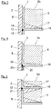
- Fig. 2 shows an embodiment of cassettes 5a, each consisting of a cylindrical shell portion 8 and a bottom 9, wherein the bottom 9 is not flush, but connects via a kind of step in the form of an arcuate inwardly extending portion 10 to the shell portion 8.
- the section 10 is designed so that the bottom 9 is indeed inserted into the top of the cassette 5 a of the next cassette below, but not completely penetrates to the shell section 8 in this, but leaves a groove-like space 11 between the cassettes.
- This groove 11 serves to receive a weld seam 12, so that it projects only slightly beyond the jacket 7.
- the section 10 forms a weld pool during welding.
- a cross-sectionally v-shaped bead 13 is provided, which engages in the expansion of the metal hydride 6 in this and on the one hand improves the heat conduction into the underlying cassette 5a and the material contained in the cassette 5a secures its position.
- the section 10 forms a step that allows on the one hand a positive insertion of an upper cassette 5a in the underlying cassette 5a and on the other hand, the necessary space (groove 11) for the weld 12 forms.
- Fig. 3 illustrated alternative cassette 5b is pot-shaped and designed substantially cylindrical, so that it can be produced in a simple manner.
- the lower edge 14 and the upper edge 15 are beveled towards the outer periphery, for receiving the weld 12th
- the cassette 5b has a two-part bottom 16, which is formed from the actual bottom 16 of a material of constant thickness and from an insert 17, which consists of good heat conducting material , here also aluminum, and has an increasing thickness from the middle to the edge.
- This insert 7 is loosely inserted in the illustrated embodiment and is fixed by the pressure of the metal hydride 6. However, it can also be additionally secured by welding.
- a cassette 5c is also substantially cup-shaped, but has a bottom 18 increasing in thickness from the center to the edge.
- the lower edge of each cassette 5c is double stepped, as shown Fig. 4 in detail proceeds.
- the first step 19 forms the necessary space for receiving the weld 12
- the second step 20 is formed so that the bottom 18 of an upper cassette can be positively inserted into the open-top side of an underlying cassette 5c.
- the second step 20 thus facilitates assembly and at the same time forms the welding bed safety.
- Fig. 5 illustrated variant is a cassette 5d similar to the cassette 5b based on Fig. 3 formed variant, ie, it has a bottom 16 of constant thickness with an insert 17, which has from the inside to the outside increasing thickness, which rests flush on the bottom 16 and on the jacket 7 and the corresponding shell portion 8. There, too, a clearance for the weld 12 is formed between adjacent cassettes 5d.
- a Unterlegeteil 21 is additionally arranged under the bottom 16, which also has to the outer edge towards increasing thickness and rests with its upper side on the underside of the bottom 16 and the outside of the shell portion 8.
- the support member 21 may either be loosely placed on the top of the underlying cassette 5d after its filling or preferably be welded to the bottom 16. In the illustrated embodiment, the composite is loose. As a result of the pressure arising when the metal hydride 6 is being stretched, the shim 21 is pressed firmly against the base 16 so that a good heat transfer takes place.
- the Unterlegeteil 21 is made of aluminum.
- FIGS. 3 to 5 The basis of the FIGS. 3 to 5 Floor formations shown serve in particular for a better heat distribution within the cassette. Due to the higher cross sections in the outer region, the heat conduction is substantially increased, so that the metal hydride 6 present in the cassettes 5 is heated or cooled substantially uniformly. The heat conduction takes place via the bottom to the shell 7 and from there to the pressure vessel wall 2. Due to the pressure of the metal hydride during expansion, the shell sections 8 apply to the pressure vessel wall and thus at least partially produce a good heat-conducting connection.
- FIGS. 2 to 5 The basis of the FIGS. 2 to 5 described individual features can be combined according to the invention with each other, this applies both in terms of floor designs as well as in terms of weld arrangements.
Landscapes
- Engineering & Computer Science (AREA)
- Chemical & Material Sciences (AREA)
- Mechanical Engineering (AREA)
- General Engineering & Computer Science (AREA)
- Organic Chemistry (AREA)
- Chemical Kinetics & Catalysis (AREA)
- Combustion & Propulsion (AREA)
- Inorganic Chemistry (AREA)
- Filling Or Discharging Of Gas Storage Vessels (AREA)
- Hydrogen, Water And Hydrids (AREA)
Claims (11)
- Dispositif de stockage de l'hydrogène avec un réservoir sous pression (1) étanche à l'hydrogène, dans lequel un anhydride métallique (6) est disposé dans des cassettes (5) perméables pour l'hydrogène, dans lequel des cassettes voisines (5) sont soudées l'une à l'autre au moins localement au moins sur le côté tourné vers le réservoir sous pression (1).
- Dispositif de stockage de l'hydrogène selon la revendication 1, dans lequel le réservoir sous pression (1) présente une forme essentiellement cylindrique et les cassettes (5) sont empilées en forme de pot et à l'intérieur du réservoir sous pression (1), de telle manière que le fond (9) d'une cassette (5) forme le couvercle de la cassette voisine (5), dans lequel des cassettes voisines (5) sont soudées l'une à l'autre de préférence sur tout leur pourtour.
- Dispositif de stockage de l'hydrogène selon l'une quelconque des revendications précédentes, dans lequel il est prévu à l'intérieur du réservoir sous pression (1) au moins un tube de remplissage et de prélèvement (4), disposé de préférence au centre et perméable à l'hydrogène, qui traverse les cassettes (5).
- Dispositif de stockage de l'hydrogène selon l'une quelconque des revendications précédentes, dans lequel le fond (9) d'une cassette (5) est de forme étagée, de telle manière qu'il s'engage par emboîtement dans le côté ouvert de la cassette voisine (5).
- Dispositif de stockage de l'hydrogène selon l'une quelconque des revendications précédentes, dans lequel les cassettes (5) sont configurées de telle manière que, lors de l'engagement de cassettes voisines, il se forme chaque fois une rainure périphérique (11), dans laquelle le cordon de soudure (12) est déposé.
- Dispositif de stockage de l'hydrogène selon l'une quelconque des revendications précédentes, dans lequel le fond (18) d'une cassette (5c) présente une épaisseur croissant radialement vers l'extérieur.
- Dispositif de stockage de l'hydrogène selon l'une quelconque des revendications précédentes, dans lequel le fond (16, 17) d'une cassette (5b) est réalisé en au moins deux parties, dans lequel une partie (17) du fond est formée par une pièce d'insertion (17), dont l'épaisseur augmente de l'intérieur vers l'extérieur.
- Dispositif de stockage de l'hydrogène selon l'une quelconque des revendications précédentes, dans lequel le fond (16, 17) d'une cassette (5) est réalisé en au moins deux parties, dans lequel une partie (18) du fond est formée par une pièce sous-jacente (18), dont l'épaisseur augmente de l'intérieur vers l'extérieur.
- Dispositif de stockage de l'hydrogène selon l'une quelconque des revendications précédentes, dans lequel le fond (9) d'une cassette (5) présente un bourrelet annulaire (13) orienté vers le côté ouvert de la cassette voisine (5) .
- Dispositif de stockage de l'hydrogène selon l'une quelconque des revendications précédentes, dans lequel les cassettes (5) sont constituées d'aluminium ou d'un alliage métallique léger perméable à l'hydrogène gazeux, bon conducteur de la chaleur et déformable.
- Utilisation d'un dispositif de stockage de l'hydrogène selon l'une quelconque des revendications précédentes pour un sous-marin.
Applications Claiming Priority (2)
| Application Number | Priority Date | Filing Date | Title |
|---|---|---|---|
| DE10309983A DE10309983A1 (de) | 2003-03-07 | 2003-03-07 | Wasserstoffspeicher |
| DE10309983 | 2003-03-07 |
Publications (3)
| Publication Number | Publication Date |
|---|---|
| EP1454876A2 EP1454876A2 (fr) | 2004-09-08 |
| EP1454876A3 EP1454876A3 (fr) | 2007-02-28 |
| EP1454876B1 true EP1454876B1 (fr) | 2016-07-20 |
Family
ID=32797867
Family Applications (1)
| Application Number | Title | Priority Date | Filing Date |
|---|---|---|---|
| EP04003367.2A Expired - Lifetime EP1454876B1 (fr) | 2003-03-07 | 2004-02-16 | Dispositif de stockage de hydrogène |
Country Status (5)
| Country | Link |
|---|---|
| EP (1) | EP1454876B1 (fr) |
| KR (1) | KR100688843B1 (fr) |
| DE (1) | DE10309983A1 (fr) |
| ES (1) | ES2599004T3 (fr) |
| PT (1) | PT1454876T (fr) |
Families Citing this family (8)
| Publication number | Priority date | Publication date | Assignee | Title |
|---|---|---|---|---|
| DE102004043947B4 (de) * | 2004-09-11 | 2006-09-21 | Prinz Gmbh | Metallhydridspeicher und Verfahren zur Herstellung derartiger Metallhydridspeicher |
| DE102006020394B4 (de) * | 2006-04-28 | 2010-07-22 | Daimler Ag | Wasserstoffspeicher und Verfahren zum Befüllen eines Wasserstoffspeichers |
| TWI429569B (zh) * | 2010-12-23 | 2014-03-11 | Asia Pacific Fuel Cell Tech | Storage tank with compartment structure |
| FR2996628B1 (fr) | 2012-10-04 | 2014-12-26 | Commissariat Energie Atomique | Reservoir de stockage d'hydrogene a hydrures metalliques de fabrication simplifiee et dispositif de stockage comportant au moins un tel reservoir |
| FR3014998B1 (fr) * | 2013-12-17 | 2016-01-22 | Commissariat Energie Atomique | Reservoir de stockage d'hydrogene a hydrures metalliques a echanges thermiques ameliores |
| DE102020214412B3 (de) | 2020-11-17 | 2022-03-31 | Thyssenkrupp Ag | Metallhydridspeicher für stationäre Anwendungen |
| KR102524152B1 (ko) * | 2021-01-31 | 2023-04-21 | 김병관 | 수소저장용기 |
| KR102885880B1 (ko) | 2025-06-09 | 2025-11-17 | 주식회사 펌스터 | 수소저장용기 |
Family Cites Families (7)
| Publication number | Priority date | Publication date | Assignee | Title |
|---|---|---|---|---|
| DE3272819D1 (en) * | 1981-03-23 | 1986-10-02 | Seikisui Chemical Co Ltd | Metal hydride reactor |
| DE3502311A1 (de) * | 1985-01-21 | 1986-07-24 | Mannesmann AG, 4000 Düsseldorf | Metallhydridspeicher und verfahren zu seiner herstellung |
| JPS63225799A (ja) | 1987-03-11 | 1988-09-20 | Yasuo Odai | 水素吸蔵合金の反応装置の製造方法 |
| FI83465C (fi) * | 1987-09-08 | 1991-07-10 | Valtion Teknillinen | Aotervinningssystem foer ackumulatorvaete i ubaotar och dykarklockor. |
| JPH09236199A (ja) * | 1996-02-29 | 1997-09-09 | Sanyo Electric Co Ltd | 分割型水素貯蔵用容器 |
| JP2002022097A (ja) | 2000-07-10 | 2002-01-23 | Toyota Motor Corp | 水素吸蔵合金の収容容器 |
| JP2002277094A (ja) * | 2001-03-21 | 2002-09-25 | Benkan Corp | 水素貯蔵装置用加熱器 |
-
2003
- 2003-03-07 DE DE10309983A patent/DE10309983A1/de not_active Withdrawn
-
2004
- 2004-02-16 PT PT4003367T patent/PT1454876T/pt unknown
- 2004-02-16 ES ES04003367.2T patent/ES2599004T3/es not_active Expired - Lifetime
- 2004-02-16 EP EP04003367.2A patent/EP1454876B1/fr not_active Expired - Lifetime
- 2004-03-04 KR KR1020040014713A patent/KR100688843B1/ko not_active Expired - Fee Related
Also Published As
| Publication number | Publication date |
|---|---|
| KR20040078893A (ko) | 2004-09-13 |
| EP1454876A3 (fr) | 2007-02-28 |
| EP1454876A2 (fr) | 2004-09-08 |
| PT1454876T (pt) | 2016-10-25 |
| DE10309983A1 (de) | 2004-09-16 |
| KR100688843B1 (ko) | 2007-02-28 |
| ES2599004T3 (es) | 2017-01-31 |
Similar Documents
| Publication | Publication Date | Title |
|---|---|---|
| DE3338879C2 (de) | Druckgasbehälter | |
| DE3502311C2 (fr) | ||
| DE3741625C2 (fr) | ||
| DE3337754C2 (de) | Wasserstoffspeicher | |
| DE3039404C2 (de) | Munition zum Auswerfen elektromagnetischer Düppel | |
| EP1454876B1 (fr) | Dispositif de stockage de hydrogène | |
| DE2504467A1 (de) | Schiff mit behaelter zum transport von fluessiggas | |
| DE1751335A1 (de) | Doppelwandiger Kuehlmittelbehaelter | |
| DE1806608A1 (de) | Verfahren und Anordnung zwecks Herstellung von Pulverkoerpern im isostatischen Druckverfahren | |
| DE102013202779A1 (de) | Druckbehälter mit Wärmetauscher für kryogen gespeichertes Medium | |
| DE1539996A1 (de) | Brennstoffelement fuer einen Kernreaktor | |
| DE2906642A1 (de) | Druckgasbehaelter | |
| EP1454875B1 (fr) | Dispositif de stockage d'hydrogène et procéde de sa production | |
| DE19837886A1 (de) | Speicherbehälter für kryogene Flüssigkeiten | |
| DE2264048A1 (de) | Hydraulischer speicher | |
| DE3223777A1 (de) | Speichermasse fuer einen druckgasbehaelter | |
| DE2310001A1 (de) | Druckbehaelter | |
| DE102020129089A1 (de) | Energiespeicherzelle, Energiespeicher sowie Verfahren zum Herstellen einer Energiespeicherzelle | |
| DE102004043947B4 (de) | Metallhydridspeicher und Verfahren zur Herstellung derartiger Metallhydridspeicher | |
| DE2642800A1 (de) | Rohrbodenanschluss fuer behaelter mit einem rohrbuendel | |
| EP1447322A1 (fr) | Sous-marin avec un réservoir contenant un gaz liquide | |
| DE19818898C2 (de) | Gasspeicher | |
| DE3042641A1 (de) | Hydrospeicher und verfahren zu seiner herstellung | |
| AT503952B1 (de) | Metallhydridspeicher | |
| DE102020201040A1 (de) | Druckgasspeicher, Brennstoffzellensystem mit Druckgasspeicher |
Legal Events
| Date | Code | Title | Description |
|---|---|---|---|
| PUAI | Public reference made under article 153(3) epc to a published international application that has entered the european phase |
Free format text: ORIGINAL CODE: 0009012 |
|
| AK | Designated contracting states |
Kind code of ref document: A2 Designated state(s): AT BE BG CH CY CZ DE DK EE ES FI FR GB GR HU IE IT LI LU MC NL PT RO SE SI SK TR |
|
| AX | Request for extension of the european patent |
Extension state: AL LT LV MK |
|
| RAP1 | Party data changed (applicant data changed or rights of an application transferred) |
Owner name: HOWALDTSWERKE-DEUTSCHE WERFT GMBH |
|
| PUAL | Search report despatched |
Free format text: ORIGINAL CODE: 0009013 |
|
| AK | Designated contracting states |
Kind code of ref document: A3 Designated state(s): AT BE BG CH CY CZ DE DK EE ES FI FR GB GR HU IE IT LI LU MC NL PT RO SE SI SK TR |
|
| AX | Request for extension of the european patent |
Extension state: AL LT LV MK |
|
| RIC1 | Information provided on ipc code assigned before grant |
Ipc: C01B 3/00 20060101AFI20040601BHEP Ipc: F17C 11/00 20060101ALI20070122BHEP |
|
| 17P | Request for examination filed |
Effective date: 20070327 |
|
| 17Q | First examination report despatched |
Effective date: 20070724 |
|
| AKX | Designation fees paid |
Designated state(s): AT BE BG CH CY CZ DE DK EE ES FI FR GB GR HU IE IT LI LU MC NL PT RO SE SI SK TR |
|
| RAP1 | Party data changed (applicant data changed or rights of an application transferred) |
Owner name: THYSSENKRUPP MARINE SYSTEMS GMBH |
|
| GRAP | Despatch of communication of intention to grant a patent |
Free format text: ORIGINAL CODE: EPIDOSNIGR1 |
|
| INTG | Intention to grant announced |
Effective date: 20160329 |
|
| GRAS | Grant fee paid |
Free format text: ORIGINAL CODE: EPIDOSNIGR3 |
|
| GRAA | (expected) grant |
Free format text: ORIGINAL CODE: 0009210 |
|
| AK | Designated contracting states |
Kind code of ref document: B1 Designated state(s): AT BE BG CH CY CZ DE DK EE ES FI FR GB GR HU IE IT LI LU MC NL PT RO SE SI SK TR |
|
| REG | Reference to a national code |
Ref country code: DE Ref legal event code: R081 Ref document number: 502004015256 Country of ref document: DE Owner name: THYSSENKRUPP MARINE SYSTEMS GMBH, DE Free format text: FORMER OWNER: HOWALDTSWERKE - DEUTSCHE WERFT AG, 24143 KIEL, DE Ref country code: GB Ref legal event code: FG4D Free format text: NOT ENGLISH |
|
| REG | Reference to a national code |
Ref country code: CH Ref legal event code: EP |
|
| REG | Reference to a national code |
Ref country code: IE Ref legal event code: FG4D Free format text: LANGUAGE OF EP DOCUMENT: GERMAN |
|
| REG | Reference to a national code |
Ref country code: AT Ref legal event code: REF Ref document number: 813910 Country of ref document: AT Kind code of ref document: T Effective date: 20160815 |
|
| REG | Reference to a national code |
Ref country code: DE Ref legal event code: R096 Ref document number: 502004015256 Country of ref document: DE |
|
| REG | Reference to a national code |
Ref country code: NL Ref legal event code: FP |
|
| REG | Reference to a national code |
Ref country code: PT Ref legal event code: SC4A Ref document number: 1454876 Country of ref document: PT Date of ref document: 20161025 Kind code of ref document: T Free format text: AVAILABILITY OF NATIONAL TRANSLATION Effective date: 20161018 |
|
| REG | Reference to a national code |
Ref country code: SE Ref legal event code: TRGR |
|
| PG25 | Lapsed in a contracting state [announced via postgrant information from national office to epo] |
Ref country code: FI Free format text: LAPSE BECAUSE OF FAILURE TO SUBMIT A TRANSLATION OF THE DESCRIPTION OR TO PAY THE FEE WITHIN THE PRESCRIBED TIME-LIMIT Effective date: 20160720 |
|
| REG | Reference to a national code |
Ref country code: ES Ref legal event code: FG2A Ref document number: 2599004 Country of ref document: ES Kind code of ref document: T3 Effective date: 20170131 |
|
| REG | Reference to a national code |
Ref country code: FR Ref legal event code: PLFP Year of fee payment: 14 |
|
| REG | Reference to a national code |
Ref country code: GR Ref legal event code: EP Ref document number: 20160402552 Country of ref document: GR Effective date: 20170130 |
|
| REG | Reference to a national code |
Ref country code: DE Ref legal event code: R097 Ref document number: 502004015256 Country of ref document: DE |
|
| PG25 | Lapsed in a contracting state [announced via postgrant information from national office to epo] |
Ref country code: RO Free format text: LAPSE BECAUSE OF FAILURE TO SUBMIT A TRANSLATION OF THE DESCRIPTION OR TO PAY THE FEE WITHIN THE PRESCRIBED TIME-LIMIT Effective date: 20160720 Ref country code: EE Free format text: LAPSE BECAUSE OF FAILURE TO SUBMIT A TRANSLATION OF THE DESCRIPTION OR TO PAY THE FEE WITHIN THE PRESCRIBED TIME-LIMIT Effective date: 20160720 |
|
| PLBE | No opposition filed within time limit |
Free format text: ORIGINAL CODE: 0009261 |
|
| STAA | Information on the status of an ep patent application or granted ep patent |
Free format text: STATUS: NO OPPOSITION FILED WITHIN TIME LIMIT |
|
| PG25 | Lapsed in a contracting state [announced via postgrant information from national office to epo] |
Ref country code: SK Free format text: LAPSE BECAUSE OF FAILURE TO SUBMIT A TRANSLATION OF THE DESCRIPTION OR TO PAY THE FEE WITHIN THE PRESCRIBED TIME-LIMIT Effective date: 20160720 Ref country code: BG Free format text: LAPSE BECAUSE OF FAILURE TO SUBMIT A TRANSLATION OF THE DESCRIPTION OR TO PAY THE FEE WITHIN THE PRESCRIBED TIME-LIMIT Effective date: 20161020 Ref country code: CZ Free format text: LAPSE BECAUSE OF FAILURE TO SUBMIT A TRANSLATION OF THE DESCRIPTION OR TO PAY THE FEE WITHIN THE PRESCRIBED TIME-LIMIT Effective date: 20160720 Ref country code: DK Free format text: LAPSE BECAUSE OF FAILURE TO SUBMIT A TRANSLATION OF THE DESCRIPTION OR TO PAY THE FEE WITHIN THE PRESCRIBED TIME-LIMIT Effective date: 20160720 Ref country code: BE Free format text: LAPSE BECAUSE OF NON-PAYMENT OF DUE FEES Effective date: 20170228 |
|
| 26N | No opposition filed |
Effective date: 20170421 |
|
| REG | Reference to a national code |
Ref country code: DE Ref legal event code: R084 Ref document number: 502004015256 Country of ref document: DE |
|
| PG25 | Lapsed in a contracting state [announced via postgrant information from national office to epo] |
Ref country code: SI Free format text: LAPSE BECAUSE OF FAILURE TO SUBMIT A TRANSLATION OF THE DESCRIPTION OR TO PAY THE FEE WITHIN THE PRESCRIBED TIME-LIMIT Effective date: 20160720 |
|
| PG25 | Lapsed in a contracting state [announced via postgrant information from national office to epo] |
Ref country code: MC Free format text: LAPSE BECAUSE OF FAILURE TO SUBMIT A TRANSLATION OF THE DESCRIPTION OR TO PAY THE FEE WITHIN THE PRESCRIBED TIME-LIMIT Effective date: 20160720 |
|
| REG | Reference to a national code |
Ref country code: CH Ref legal event code: PL |
|
| PG25 | Lapsed in a contracting state [announced via postgrant information from national office to epo] |
Ref country code: CH Free format text: LAPSE BECAUSE OF NON-PAYMENT OF DUE FEES Effective date: 20170228 Ref country code: LI Free format text: LAPSE BECAUSE OF NON-PAYMENT OF DUE FEES Effective date: 20170228 |
|
| REG | Reference to a national code |
Ref country code: IE Ref legal event code: MM4A |
|
| PG25 | Lapsed in a contracting state [announced via postgrant information from national office to epo] |
Ref country code: LU Free format text: LAPSE BECAUSE OF NON-PAYMENT OF DUE FEES Effective date: 20170216 |
|
| REG | Reference to a national code |
Ref country code: BE Ref legal event code: MM Effective date: 20170228 |
|
| REG | Reference to a national code |
Ref country code: FR Ref legal event code: PLFP Year of fee payment: 15 |
|
| PG25 | Lapsed in a contracting state [announced via postgrant information from national office to epo] |
Ref country code: IE Free format text: LAPSE BECAUSE OF NON-PAYMENT OF DUE FEES Effective date: 20170216 |
|
| PG25 | Lapsed in a contracting state [announced via postgrant information from national office to epo] |
Ref country code: HU Free format text: LAPSE BECAUSE OF FAILURE TO SUBMIT A TRANSLATION OF THE DESCRIPTION OR TO PAY THE FEE WITHIN THE PRESCRIBED TIME-LIMIT; INVALID AB INITIO Effective date: 20040216 |
|
| REG | Reference to a national code |
Ref country code: DE Ref legal event code: R081 Ref document number: 502004015256 Country of ref document: DE Owner name: THYSSENKRUPP MARINE SYSTEMS GMBH, DE Free format text: FORMER OWNER: THYSSENKRUPP MARINE SYSTEMS GMBH, 24143 KIEL, DE |
|
| PG25 | Lapsed in a contracting state [announced via postgrant information from national office to epo] |
Ref country code: CY Free format text: LAPSE BECAUSE OF NON-PAYMENT OF DUE FEES Effective date: 20160720 |
|
| PGFP | Annual fee paid to national office [announced via postgrant information from national office to epo] |
Ref country code: NL Payment date: 20230216 Year of fee payment: 20 |
|
| PGFP | Annual fee paid to national office [announced via postgrant information from national office to epo] |
Ref country code: FR Payment date: 20230220 Year of fee payment: 20 Ref country code: AT Payment date: 20230217 Year of fee payment: 20 |
|
| PGFP | Annual fee paid to national office [announced via postgrant information from national office to epo] |
Ref country code: TR Payment date: 20230215 Year of fee payment: 20 Ref country code: SE Payment date: 20230216 Year of fee payment: 20 Ref country code: PT Payment date: 20230202 Year of fee payment: 20 Ref country code: IT Payment date: 20230223 Year of fee payment: 20 Ref country code: GR Payment date: 20230220 Year of fee payment: 20 Ref country code: GB Payment date: 20230220 Year of fee payment: 20 Ref country code: DE Payment date: 20220801 Year of fee payment: 20 |
|
| PGFP | Annual fee paid to national office [announced via postgrant information from national office to epo] |
Ref country code: ES Payment date: 20230424 Year of fee payment: 20 |
|
| REG | Reference to a national code |
Ref country code: DE Ref legal event code: R071 Ref document number: 502004015256 Country of ref document: DE |
|
| REG | Reference to a national code |
Ref country code: NL Ref legal event code: MK Effective date: 20240215 |
|
| REG | Reference to a national code |
Ref country code: GB Ref legal event code: PE20 Expiry date: 20240215 |
|
| REG | Reference to a national code |
Ref country code: AT Ref legal event code: MK07 Ref document number: 813910 Country of ref document: AT Kind code of ref document: T Effective date: 20240216 |
|
| PG25 | Lapsed in a contracting state [announced via postgrant information from national office to epo] |
Ref country code: PT Free format text: LAPSE BECAUSE OF EXPIRATION OF PROTECTION Effective date: 20240226 Ref country code: GB Free format text: LAPSE BECAUSE OF EXPIRATION OF PROTECTION Effective date: 20240215 |
|
| REG | Reference to a national code |
Ref country code: ES Ref legal event code: FD2A Effective date: 20240506 |
|
| PG25 | Lapsed in a contracting state [announced via postgrant information from national office to epo] |
Ref country code: ES Free format text: LAPSE BECAUSE OF EXPIRATION OF PROTECTION Effective date: 20240217 |
|
| PG25 | Lapsed in a contracting state [announced via postgrant information from national office to epo] |
Ref country code: ES Free format text: LAPSE BECAUSE OF EXPIRATION OF PROTECTION Effective date: 20240217 |