EP1455053A2 - Schaufelprofil einer Turbinen-Statorschaufel - Google Patents
Schaufelprofil einer Turbinen-Statorschaufel Download PDFInfo
- Publication number
- EP1455053A2 EP1455053A2 EP04251229A EP04251229A EP1455053A2 EP 1455053 A2 EP1455053 A2 EP 1455053A2 EP 04251229 A EP04251229 A EP 04251229A EP 04251229 A EP04251229 A EP 04251229A EP 1455053 A2 EP1455053 A2 EP 1455053A2
- Authority
- EP
- European Patent Office
- Prior art keywords
- airfoil
- values
- turbine
- inches
- distances
- Prior art date
- Legal status (The legal status is an assumption and is not a legal conclusion. Google has not performed a legal analysis and makes no representation as to the accuracy of the status listed.)
- Withdrawn
Links
Images




Classifications
-
- F—MECHANICAL ENGINEERING; LIGHTING; HEATING; WEAPONS; BLASTING
- F01—MACHINES OR ENGINES IN GENERAL; ENGINE PLANTS IN GENERAL; STEAM ENGINES
- F01D—NON-POSITIVE DISPLACEMENT MACHINES OR ENGINES, e.g. STEAM TURBINES
- F01D9/00—Stators
- F01D9/02—Nozzles; Nozzle boxes; Stator blades; Guide conduits, e.g. individual nozzles
- F01D9/04—Nozzles; Nozzle boxes; Stator blades; Guide conduits, e.g. individual nozzles forming ring or sector
- F01D9/041—Nozzles; Nozzle boxes; Stator blades; Guide conduits, e.g. individual nozzles forming ring or sector using blades
-
- F—MECHANICAL ENGINEERING; LIGHTING; HEATING; WEAPONS; BLASTING
- F01—MACHINES OR ENGINES IN GENERAL; ENGINE PLANTS IN GENERAL; STEAM ENGINES
- F01D—NON-POSITIVE DISPLACEMENT MACHINES OR ENGINES, e.g. STEAM TURBINES
- F01D5/00—Blades; Blade-carrying members; Heating, heat-insulating, cooling or antivibration means on the blades or the members
- F01D5/12—Blades
- F01D5/14—Form or construction
- F01D5/141—Shape, i.e. outer, aerodynamic form
-
- F—MECHANICAL ENGINEERING; LIGHTING; HEATING; WEAPONS; BLASTING
- F05—INDEXING SCHEMES RELATING TO ENGINES OR PUMPS IN VARIOUS SUBCLASSES OF CLASSES F01-F04
- F05D—INDEXING SCHEME FOR ASPECTS RELATING TO NON-POSITIVE-DISPLACEMENT MACHINES OR ENGINES, GAS-TURBINES OR JET-PROPULSION PLANTS
- F05D2220/00—Application
- F05D2220/30—Application in turbines
- F05D2220/32—Application in turbines in gas turbines
- F05D2220/321—Application in turbines in gas turbines for a special turbine stage
-
- F—MECHANICAL ENGINEERING; LIGHTING; HEATING; WEAPONS; BLASTING
- F05—INDEXING SCHEMES RELATING TO ENGINES OR PUMPS IN VARIOUS SUBCLASSES OF CLASSES F01-F04
- F05D—INDEXING SCHEME FOR ASPECTS RELATING TO NON-POSITIVE-DISPLACEMENT MACHINES OR ENGINES, GAS-TURBINES OR JET-PROPULSION PLANTS
- F05D2240/00—Components
- F05D2240/10—Stators
- F05D2240/12—Fluid guiding means, e.g. vanes
- F05D2240/128—Nozzles
-
- F—MECHANICAL ENGINEERING; LIGHTING; HEATING; WEAPONS; BLASTING
- F05—INDEXING SCHEMES RELATING TO ENGINES OR PUMPS IN VARIOUS SUBCLASSES OF CLASSES F01-F04
- F05D—INDEXING SCHEME FOR ASPECTS RELATING TO NON-POSITIVE-DISPLACEMENT MACHINES OR ENGINES, GAS-TURBINES OR JET-PROPULSION PLANTS
- F05D2240/00—Components
- F05D2240/80—Platforms for stationary or moving blades
-
- F—MECHANICAL ENGINEERING; LIGHTING; HEATING; WEAPONS; BLASTING
- F05—INDEXING SCHEMES RELATING TO ENGINES OR PUMPS IN VARIOUS SUBCLASSES OF CLASSES F01-F04
- F05D—INDEXING SCHEME FOR ASPECTS RELATING TO NON-POSITIVE-DISPLACEMENT MACHINES OR ENGINES, GAS-TURBINES OR JET-PROPULSION PLANTS
- F05D2250/00—Geometry
- F05D2250/20—Three-dimensional
-
- F—MECHANICAL ENGINEERING; LIGHTING; HEATING; WEAPONS; BLASTING
- F05—INDEXING SCHEMES RELATING TO ENGINES OR PUMPS IN VARIOUS SUBCLASSES OF CLASSES F01-F04
- F05D—INDEXING SCHEME FOR ASPECTS RELATING TO NON-POSITIVE-DISPLACEMENT MACHINES OR ENGINES, GAS-TURBINES OR JET-PROPULSION PLANTS
- F05D2250/00—Geometry
- F05D2250/70—Shape
-
- F—MECHANICAL ENGINEERING; LIGHTING; HEATING; WEAPONS; BLASTING
- F05—INDEXING SCHEMES RELATING TO ENGINES OR PUMPS IN VARIOUS SUBCLASSES OF CLASSES F01-F04
- F05D—INDEXING SCHEME FOR ASPECTS RELATING TO NON-POSITIVE-DISPLACEMENT MACHINES OR ENGINES, GAS-TURBINES OR JET-PROPULSION PLANTS
- F05D2250/00—Geometry
- F05D2250/70—Shape
- F05D2250/74—Shape given by a set or table of xyz-coordinates
Definitions
- the present invention relates to an airfoil for a nozzle stage of a gas turbine and particularly relates to an airfoil for a third stage nozzle of a gas turbine.
- an airfoil shape for a nozzle stage of a gas turbine preferably the third stage nozzle, that enhances the performance of the gas turbine.
- the airfoil shape hereof improves the interaction between various stages in the turbine, affords improved aerodynamic efficiency through the third stage and improves the third stage blade loading.
- the profile of each second stage nozzle airfoil which in part defines the hot gas path annulus about the nozzle stage meets the requirements for improved stage efficiency, as well as parts life and manufacturability.
- a turbine nozzle including an airfoil having an airfoil shape, the airfoil having a nominal profile substantially in accordance with Cartesian coordinate values of X, Y and Z set forth in Table I wherein the Z values are non-dimensional values from 0 to 1 convertible to Z distances in inches by multiplying the Z values of Table I by a height of the airfoil in inches, and wherein the X and Y values are distances in inches which, when connected by smooth continuing arcs, define airfoil profile sections at each distance Z, the profile sections at the Z distances being joined smoothly with one another to form a complete airfoil shape.
- a turbine nozzle including an airfoil having an uncoated nominal airfoil profile substantially in accordance with Cartesian coordinate values of X, Y and Z set forth in Table I wherein the Z values are non-dimensional values from 0 to 1 convertible to Z distances in inches by multiplying the Z values of Table I by a height of the airfoil in inches, and wherein the X and Y values are distances in inches which, when connected by smooth continuing arcs, define airfoil profile sections at each distance Z, the profile sections at the Z distances being joined smoothly with one another to form a complete airfoil shape, the X, Y and Z distances being scalable as a function of the same constant or number to provide a scaled-up or scaled-down airfoil.
- a turbine comprising a turbine stage having a plurality of nozzles, each of the nozzles including an airfoil having an airfoil shape, the airfoil having a nominal profile substantially in accordance with Cartesian coordinate values of X, Y and Z set forth in Table I wherein the Z values are non-dimensional values from 0 to 1 convertible to Z distances in inches by multiplying the Z values of Table I by a height of the airfoil in inches, and wherein X and Y values are distances in inches which, when connected by smooth continuing arcs, define airfoil profile sections at each distance Z, the profile sections at the Z distances being joined smoothly with one another to form a complete airfoil shape.
- a multi-stage turbine section for a gas turbine 12 including a plurality of turbine stages.
- the first stage comprises a plurality of circumferentially spaced nozzle or blades 14 and buckets 16, the nozzles being circumferentially spaced one from the other and fixed about the axis of the turbine rotor 15.
- the buckets 16 are mounted on and circumferentially spaced about the rotor 15.
- a second stage of the turbine 12 is also illustrated, including a plurality of circumferentially spaced nozzles 18 and a plurality of buckets 20 mounted on the rotor 15.
- a third stage is also illustrated, including a plurality of circumferentially spaced nozzles 22 and buckets 24. It will be appreciated that the nozzles and buckets lie in the turbine's hot gas path indicated by the arrow 26.
- the nozzle stages extend generally radially between inner and outer bands 28 and 30, respectively, which also in part define the hot gas path 26 through turbine 12.
- the nozzles 22 are provided as either singlets, doublets or triplets with associated inner and outer bands which are secured together to form a circumferential array of nozzles about the axis of rotation of the rotor.
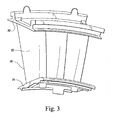
- the nozzles 22 are preferably provided in triplets as illustrated. It will be appreciated that each nozzie 22 is in the shape of an airfoil or airfoil-shaped blade 32, as illustrated in Figure 5.
- each nozzle 22 has a profile at any cross-section between the inner and outer bands 28 and 30, respectively, in the shape of an airfoil 32.
- the airfoil shape of the third stage nozzle airfoil which optimizes the guided hot gas turning and overall efficiency of the turbine, there are a unique set or loci of points in space that meet the stage requirements and can be manufactured. This unique loci of points meets the requirements for nozzle loading and stage efficiency and are arrived at by iteration between aerodynamics and nozzle mechanical loading, enabling the turbine to run in an efficient, safe and smooth manner.
- the loci which defines the nozzle airfoil profile comprises a set of 600 points.
- a Cartesian coordinate system of X, Y and Z values given in Table I below defines the profile of each nozzle airfoil.
- the values for the X and Y coordinates are set forth in inches in Table I, although other units of dimensions may be used when the values are appropriately converted.
- the Z values set forth in Table I are non-dimensional values from 0 to 1. To convert each Z value to a Z distance in inches, the non-dimensional Z values given in Table I are multiplied by a constant in inches, e.g., the height of the nozzle airfoil.
- the airfoil height H may be measured from a point at the intersection of the trailing edge 38 of the nozzle 22 and the outer band 30 along a radius which intersects the inner band aft of the trailing edge 38 at 37 ( Figure 4) and is about 8.125 inches.
- the preferred distance D ( Figure 4) from the point of intersection 35 of each nozzle of the third stage from the rotor axis 34 is 28.930 inches
- the coordinate system has orthogonally related X, Y and Z axes with the Z axis extending perpendicular to a plane normal to a plane containing the X and Y values.
- the Y axis lies parallel to the turbine rotor centerline, i.e., the rotary axis 34 and is positive forward to aft.
- the Z direction is negative in a radial inward direction and the X direction is negative in a tangential counterclockwise direction as viewed in the aft direction.
- each profile section at each distance Z is fixed.
- the surface profiles of the various surface locations between the distances Z are determined by smoothly connecting the adjacent cross-sections to one another to form the airfoil.
- the values set forth in Table I represent the airfoil profiles at ambient, non-operating or non-hot conditions and are for an uncoated airfoil.
- the sign convention assigns a positive value to Z values and positive and negative values for X and Y coordinates as typically used in the Cartesian coordinate system.
- the Table I values are generated and shown to three decimal places for determining the profile of the nozzle airfoil.
- the actual profile of the nozzle airfoil may lie in a range of variations between measured points on an airfoil surface and their ideal position as listed in Table I.
- the design is robust to this variation to the extent that mechanical and aerodynamic functions are not impaired.
- ⁇ typical manufacturing tolerances i.e., ⁇ values, including any coating thicknesses, are additive to the X and Y values given in Table I below. Accordingly, a distance of ⁇ 0.100 inches in a direction normal to any surface location along the airfoil profile defines an airfoil profile envelope for this particular third stage nozzle airfoil.
- the airfoil profile disclosed in the above table may be scaled up or down geometrically for use in other similar turbine designs. Consequently, the coordinate values set forth in Table I may be scaled upwardly or downwardly such that the airfoil section shape remains unchanged.
- a scaled version of the coordinates in Table I is represented by X, Y and Z distances in inches, multiplied or divided by a constant number.
Landscapes
- Engineering & Computer Science (AREA)
- Mechanical Engineering (AREA)
- General Engineering & Computer Science (AREA)
- Physics & Mathematics (AREA)
- Fluid Mechanics (AREA)
- Turbine Rotor Nozzle Sealing (AREA)
- Developing Agents For Electrophotography (AREA)
- Materials For Photolithography (AREA)
Applications Claiming Priority (2)
| Application Number | Priority Date | Filing Date | Title |
|---|---|---|---|
| US376246 | 2003-03-03 | ||
| US10/376,246 US6887041B2 (en) | 2003-03-03 | 2003-03-03 | Airfoil shape for a turbine nozzle |
Publications (2)
| Publication Number | Publication Date |
|---|---|
| EP1455053A2 true EP1455053A2 (de) | 2004-09-08 |
| EP1455053A3 EP1455053A3 (de) | 2007-01-31 |
Family
ID=32824729
Family Applications (1)
| Application Number | Title | Priority Date | Filing Date |
|---|---|---|---|
| EP04251229A Withdrawn EP1455053A3 (de) | 2003-03-03 | 2004-03-03 | Schaufelprofil einer Turbinen-Statorschaufel |
Country Status (4)
| Country | Link |
|---|---|
| US (1) | US6887041B2 (de) |
| EP (1) | EP1455053A3 (de) |
| JP (1) | JP2004263699A (de) |
| TW (1) | TW200427918A (de) |
Cited By (10)
| Publication number | Priority date | Publication date | Assignee | Title |
|---|---|---|---|---|
| WO2008090394A3 (en) * | 2005-12-29 | 2009-06-18 | Rolls Royce Power Eng | Second stage turbine airfoil |
| US7618240B2 (en) | 2005-12-29 | 2009-11-17 | Rolls-Royce Power Engineering Plc | Airfoil for a first stage nozzle guide vane |
| US7632072B2 (en) | 2005-12-29 | 2009-12-15 | Rolls-Royce Power Engineering Plc | Third stage turbine airfoil |
| US7648334B2 (en) | 2005-12-29 | 2010-01-19 | Rolls-Royce Power Engineering Plc | Airfoil for a second stage nozzle guide vane |
| US7648340B2 (en) | 2005-12-29 | 2010-01-19 | Rolls-Royce Power Engineering Plc | First stage turbine airfoil |
| EP1760263A3 (de) * | 2005-08-30 | 2010-03-10 | General Electric Company | Optimiertes Leitschaufel-Profil |
| US7722329B2 (en) | 2005-12-29 | 2010-05-25 | Rolls-Royce Power Engineering Plc | Airfoil for a third stage nozzle guide vane |
| GB2471185A (en) * | 2009-06-17 | 2010-12-22 | Gen Electric | Prechorded turbine nozzle |
| US8757968B2 (en) | 2010-07-26 | 2014-06-24 | Snecma | Optimized aerodynamic profile for a turbine vane, in particular for a nozzle of the third stage of a turbine |
| US8814511B2 (en) | 2011-08-09 | 2014-08-26 | General Electric Company | Turbomachine component having an airfoil core shape |
Families Citing this family (43)
| Publication number | Priority date | Publication date | Assignee | Title |
|---|---|---|---|---|
| US7001147B1 (en) * | 2004-07-28 | 2006-02-21 | General Electric Company | Airfoil shape and sidewall flowpath surfaces for a turbine nozzle |
| US20060216144A1 (en) * | 2005-03-28 | 2006-09-28 | Sullivan Michael A | First and second stage turbine airfoil shapes |
| US7330239B2 (en) * | 2005-04-08 | 2008-02-12 | Asml Netherlands B.V. | Lithographic apparatus and device manufacturing method utilizing a blazing portion of a contrast device |
| US8016551B2 (en) | 2005-11-03 | 2011-09-13 | Honeywell International, Inc. | Reverse curved nozzle for radial inflow turbines |
| US7377743B2 (en) * | 2005-12-19 | 2008-05-27 | General Electric Company | Countercooled turbine nozzle |
| US7329092B2 (en) * | 2006-01-27 | 2008-02-12 | General Electric Company | Stator blade airfoil profile for a compressor |
| US7329093B2 (en) * | 2006-01-27 | 2008-02-12 | General Electric Company | Nozzle blade airfoil profile for a turbine |
| US7306436B2 (en) * | 2006-03-02 | 2007-12-11 | Pratt & Whitney Canada Corp. | HP turbine blade airfoil profile |
| FR2899269A1 (fr) * | 2006-03-30 | 2007-10-05 | Snecma Sa | Aube de redresseur optimisee, secteur de redresseurs, etage de compression, compresseur et turbomachine comportant une telle aube |
| US7581930B2 (en) * | 2006-08-16 | 2009-09-01 | United Technologies Corporation | High lift transonic turbine blade |
| US7611326B2 (en) * | 2006-09-06 | 2009-11-03 | Pratt & Whitney Canada Corp. | HP turbine vane airfoil profile |
| US7572104B2 (en) * | 2006-10-25 | 2009-08-11 | General Electric Company | Airfoil shape for a compressor |
| US7513748B2 (en) * | 2006-10-25 | 2009-04-07 | General Electric Company | Airfoil shape for a compressor |
| US7517197B2 (en) * | 2006-10-25 | 2009-04-14 | General Electric Company | Airfoil shape for a compressor |
| US7572105B2 (en) * | 2006-10-25 | 2009-08-11 | General Electric Company | Airfoil shape for a compressor |
| US7510378B2 (en) * | 2006-10-25 | 2009-03-31 | General Electric Company | Airfoil shape for a compressor |
| US7566202B2 (en) * | 2006-10-25 | 2009-07-28 | General Electric Company | Airfoil shape for a compressor |
| US7497663B2 (en) * | 2006-10-26 | 2009-03-03 | General Electric Company | Rotor blade profile optimization |
| US7497665B2 (en) * | 2006-11-02 | 2009-03-03 | General Electric Company | Airfoil shape for a compressor |
| US7568892B2 (en) * | 2006-11-02 | 2009-08-04 | General Electric Company | Airfoil shape for a compressor |
| US7559748B2 (en) * | 2006-11-28 | 2009-07-14 | Pratt & Whitney Canada Corp. | LP turbine blade airfoil profile |
| US7695242B2 (en) * | 2006-12-05 | 2010-04-13 | Fuller Howard J | Wind turbine for generation of electric power |
| GB0700142D0 (en) * | 2007-01-05 | 2007-02-14 | Rolls Royce Plc | Nozzle guide vane arrangement |
| US20090169369A1 (en) * | 2007-12-29 | 2009-07-02 | General Electric Company | Turbine nozzle segment and assembly |
| US20090274562A1 (en) * | 2008-05-02 | 2009-11-05 | United Technologies Corporation | Coated turbine-stage nozzle segments |
| US8113786B2 (en) * | 2008-09-12 | 2012-02-14 | General Electric Company | Stator vane profile optimization |
| US8133016B2 (en) * | 2009-01-02 | 2012-03-13 | General Electric Company | Airfoil profile for a second stage turbine nozzle |
| US8573945B2 (en) * | 2009-11-13 | 2013-11-05 | Alstom Technology Ltd. | Compressor stator vane |
| US8393870B2 (en) | 2010-09-08 | 2013-03-12 | United Technologies Corporation | Turbine blade airfoil |
| US8602740B2 (en) | 2010-09-08 | 2013-12-10 | United Technologies Corporation | Turbine vane airfoil |
| US8556588B2 (en) | 2011-06-03 | 2013-10-15 | General Electric Company | Airfoil shape for a compressor |
| US8814526B2 (en) | 2011-11-28 | 2014-08-26 | General Electric Company | Turbine nozzle airfoil profile |
| US8807950B2 (en) * | 2011-11-28 | 2014-08-19 | General Electric Company | Turbine nozzle airfoil profile |
| US9011101B2 (en) | 2011-11-28 | 2015-04-21 | General Electric Company | Turbine bucket airfoil profile |
| US8734116B2 (en) | 2011-11-28 | 2014-05-27 | General Electric Company | Turbine bucket airfoil profile |
| US8740570B2 (en) | 2011-11-28 | 2014-06-03 | General Electric Company | Turbine bucket airfoil profile |
| US8827641B2 (en) | 2011-11-28 | 2014-09-09 | General Electric Company | Turbine nozzle airfoil profile |
| US9145777B2 (en) * | 2012-07-24 | 2015-09-29 | General Electric Company | Article of manufacture |
| WO2015112222A2 (en) | 2013-11-04 | 2015-07-30 | United Technologies Corporation | Gas turbine engine airfoil profile |
| US10443393B2 (en) * | 2016-07-13 | 2019-10-15 | Safran Aircraft Engines | Optimized aerodynamic profile for a turbine vane, in particular for a nozzle of the seventh stage of a turbine |
| US10443392B2 (en) * | 2016-07-13 | 2019-10-15 | Safran Aircraft Engines | Optimized aerodynamic profile for a turbine vane, in particular for a nozzle of the second stage of a turbine |
| US10837298B2 (en) * | 2018-08-21 | 2020-11-17 | Chromalloy Gas Turbine Llc | First stage turbine nozzle |
| US11326460B1 (en) * | 2021-07-15 | 2022-05-10 | Doosan Heavy Industries & Construction Co., Ltd. | Airfoil profile for a turbine nozzle |
Family Cites Families (5)
| Publication number | Priority date | Publication date | Assignee | Title |
|---|---|---|---|---|
| US5980209A (en) * | 1997-06-27 | 1999-11-09 | General Electric Co. | Turbine blade with enhanced cooling and profile optimization |
| US6398489B1 (en) * | 2001-02-08 | 2002-06-04 | General Electric Company | Airfoil shape for a turbine nozzle |
| US6503054B1 (en) * | 2001-07-13 | 2003-01-07 | General Electric Company | Second-stage turbine nozzle airfoil |
| US6461109B1 (en) * | 2001-07-13 | 2002-10-08 | General Electric Company | Third-stage turbine nozzle airfoil |
| US6722853B1 (en) * | 2002-11-22 | 2004-04-20 | General Electric Company | Airfoil shape for a turbine nozzle |
-
2003
- 2003-03-03 US US10/376,246 patent/US6887041B2/en not_active Expired - Lifetime
-
2004
- 2004-02-26 TW TW093104971A patent/TW200427918A/zh unknown
- 2004-03-02 JP JP2004057358A patent/JP2004263699A/ja active Pending
- 2004-03-03 EP EP04251229A patent/EP1455053A3/de not_active Withdrawn
Cited By (14)
| Publication number | Priority date | Publication date | Assignee | Title |
|---|---|---|---|---|
| EP1760263A3 (de) * | 2005-08-30 | 2010-03-10 | General Electric Company | Optimiertes Leitschaufel-Profil |
| US7632072B2 (en) | 2005-12-29 | 2009-12-15 | Rolls-Royce Power Engineering Plc | Third stage turbine airfoil |
| US7625184B2 (en) | 2005-12-29 | 2009-12-01 | Rolls-Royce Power Engineering Plc | Second stage turbine airfoil |
| WO2008090394A3 (en) * | 2005-12-29 | 2009-06-18 | Rolls Royce Power Eng | Second stage turbine airfoil |
| US7648334B2 (en) | 2005-12-29 | 2010-01-19 | Rolls-Royce Power Engineering Plc | Airfoil for a second stage nozzle guide vane |
| US7648340B2 (en) | 2005-12-29 | 2010-01-19 | Rolls-Royce Power Engineering Plc | First stage turbine airfoil |
| US7618240B2 (en) | 2005-12-29 | 2009-11-17 | Rolls-Royce Power Engineering Plc | Airfoil for a first stage nozzle guide vane |
| US7722329B2 (en) | 2005-12-29 | 2010-05-25 | Rolls-Royce Power Engineering Plc | Airfoil for a third stage nozzle guide vane |
| GB2448087B (en) * | 2005-12-29 | 2011-06-22 | Rolls Royce Power Eng | Second Stage Turbine Airfoil |
| GB2471185A (en) * | 2009-06-17 | 2010-12-22 | Gen Electric | Prechorded turbine nozzle |
| US8328511B2 (en) | 2009-06-17 | 2012-12-11 | General Electric Company | Prechorded turbine nozzle |
| GB2471185B (en) * | 2009-06-17 | 2016-02-03 | Gen Electric | Prechorded turbine nozzle |
| US8757968B2 (en) | 2010-07-26 | 2014-06-24 | Snecma | Optimized aerodynamic profile for a turbine vane, in particular for a nozzle of the third stage of a turbine |
| US8814511B2 (en) | 2011-08-09 | 2014-08-26 | General Electric Company | Turbomachine component having an airfoil core shape |
Also Published As
| Publication number | Publication date |
|---|---|
| TW200427918A (en) | 2004-12-16 |
| US20040175271A1 (en) | 2004-09-09 |
| US6887041B2 (en) | 2005-05-03 |
| JP2004263699A (ja) | 2004-09-24 |
| EP1455053A3 (de) | 2007-01-31 |
Similar Documents
| Publication | Publication Date | Title |
|---|---|---|
| US6887041B2 (en) | Airfoil shape for a turbine nozzle | |
| US6722853B1 (en) | Airfoil shape for a turbine nozzle | |
| US6779980B1 (en) | Airfoil shape for a turbine bucket | |
| US6866477B2 (en) | Airfoil shape for a turbine nozzle | |
| US6884038B2 (en) | Airfoil shape for a turbine bucket | |
| US6910868B2 (en) | Airfoil shape for a turbine bucket | |
| US6739838B1 (en) | Airfoil shape for a turbine bucket | |
| US6779977B2 (en) | Airfoil shape for a turbine bucket | |
| US6857855B1 (en) | Airfoil shape for a turbine bucket | |
| US6685434B1 (en) | Second stage turbine bucket airfoil | |
| US6881038B1 (en) | Airfoil shape for a turbine bucket | |
| US6722852B1 (en) | Third stage turbine bucket airfoil | |
| US6769879B1 (en) | Airfoil shape for a turbine bucket | |
| US7731483B2 (en) | Airfoil shape for a turbine bucket and turbine incorporating same | |
| US6854961B2 (en) | Airfoil shape for a turbine bucket | |
| US6808368B1 (en) | Airfoil shape for a turbine bucket | |
| US7520729B2 (en) | Airfoil shape for a compressor | |
| US6715990B1 (en) | First stage turbine bucket airfoil | |
| US7534094B2 (en) | Airfoil shape for a compressor | |
| US7530793B2 (en) | Airfoil shape for a compressor | |
| US7524170B2 (en) | Airfoil shape for a compressor | |
| US7540715B2 (en) | Airfoil shape for a compressor | |
| US7988420B2 (en) | Airfoil shape for a turbine bucket and turbine incorporating same | |
| US7001147B1 (en) | Airfoil shape and sidewall flowpath surfaces for a turbine nozzle | |
| US6722851B1 (en) | Internal core profile for a turbine bucket |
Legal Events
| Date | Code | Title | Description |
|---|---|---|---|
| PUAI | Public reference made under article 153(3) epc to a published international application that has entered the european phase |
Free format text: ORIGINAL CODE: 0009012 |
|
| AK | Designated contracting states |
Kind code of ref document: A2 Designated state(s): AT BE BG CH CY CZ DE DK EE ES FI FR GB GR HU IE IT LI LU MC NL PL PT RO SE SI SK TR |
|
| AX | Request for extension of the european patent |
Extension state: AL HR LT LV MK |
|
| PUAL | Search report despatched |
Free format text: ORIGINAL CODE: 0009013 |
|
| AK | Designated contracting states |
Kind code of ref document: A3 Designated state(s): AT BE BG CH CY CZ DE DK EE ES FI FR GB GR HU IE IT LI LU MC NL PL PT RO SE SI SK TR |
|
| AX | Request for extension of the european patent |
Extension state: AL LT LV MK |
|
| RIC1 | Information provided on ipc code assigned before grant |
Ipc: F01D 5/14 20060101ALI20061222BHEP Ipc: F01D 9/02 20060101AFI20040421BHEP |
|
| 17P | Request for examination filed |
Effective date: 20070731 |
|
| AKX | Designation fees paid |
Designated state(s): CH DE FR GB LI |
|
| 17Q | First examination report despatched |
Effective date: 20071024 |
|
| STAA | Information on the status of an ep patent application or granted ep patent |
Free format text: STATUS: THE APPLICATION IS DEEMED TO BE WITHDRAWN |
|
| 18D | Application deemed to be withdrawn |
Effective date: 20101001 |