EP1455064A2 - Entraínement par friction de roue coopérant avec entraínement à courroie pour des accessoires d'un moteur, pour un accessoire de moteur arrangé séparement - Google Patents
Entraínement par friction de roue coopérant avec entraínement à courroie pour des accessoires d'un moteur, pour un accessoire de moteur arrangé séparement Download PDFInfo
- Publication number
- EP1455064A2 EP1455064A2 EP04001909A EP04001909A EP1455064A2 EP 1455064 A2 EP1455064 A2 EP 1455064A2 EP 04001909 A EP04001909 A EP 04001909A EP 04001909 A EP04001909 A EP 04001909A EP 1455064 A2 EP1455064 A2 EP 1455064A2
- Authority
- EP
- European Patent Office
- Prior art keywords
- control device
- eccentric
- friction wheel
- friction
- wheel
- Prior art date
- Legal status (The legal status is an assumption and is not a legal conclusion. Google has not performed a legal analysis and makes no representation as to the accuracy of the status listed.)
- Granted
Links
- 238000002485 combustion reaction Methods 0.000 claims abstract description 17
- 239000002826 coolant Substances 0.000 claims abstract description 12
- 239000012528 membrane Substances 0.000 claims description 8
- 239000010687 lubricating oil Substances 0.000 claims description 5
- 230000005540 biological transmission Effects 0.000 claims description 4
- 238000010276 construction Methods 0.000 description 3
- 239000002184 metal Substances 0.000 description 2
- 238000005096 rolling process Methods 0.000 description 2
- 230000001133 acceleration Effects 0.000 description 1
- 238000011109 contamination Methods 0.000 description 1
- 238000001816 cooling Methods 0.000 description 1
- 230000008030 elimination Effects 0.000 description 1
- 238000003379 elimination reaction Methods 0.000 description 1
- 238000005461 lubrication Methods 0.000 description 1
- 230000000149 penetrating effect Effects 0.000 description 1
- 230000002787 reinforcement Effects 0.000 description 1
Images
Classifications
-
- F—MECHANICAL ENGINEERING; LIGHTING; HEATING; WEAPONS; BLASTING
- F02—COMBUSTION ENGINES; HOT-GAS OR COMBUSTION-PRODUCT ENGINE PLANTS
- F02B—INTERNAL-COMBUSTION PISTON ENGINES; COMBUSTION ENGINES IN GENERAL
- F02B67/00—Engines characterised by the arrangement of auxiliary apparatus not being otherwise provided for, e.g. the apparatus having different functions; Driving auxiliary apparatus from engines, not otherwise provided for
- F02B67/04—Engines characterised by the arrangement of auxiliary apparatus not being otherwise provided for, e.g. the apparatus having different functions; Driving auxiliary apparatus from engines, not otherwise provided for of mechanically-driven auxiliary apparatus
- F02B67/06—Engines characterised by the arrangement of auxiliary apparatus not being otherwise provided for, e.g. the apparatus having different functions; Driving auxiliary apparatus from engines, not otherwise provided for of mechanically-driven auxiliary apparatus driven by means of chains, belts, or like endless members
-
- F—MECHANICAL ENGINEERING; LIGHTING; HEATING; WEAPONS; BLASTING
- F16—ENGINEERING ELEMENTS AND UNITS; GENERAL MEASURES FOR PRODUCING AND MAINTAINING EFFECTIVE FUNCTIONING OF MACHINES OR INSTALLATIONS; THERMAL INSULATION IN GENERAL
- F16H—GEARING
- F16H13/00—Gearing for conveying rotary motion with constant gear ratio by friction between rotary members
- F16H13/10—Means for influencing the pressure between the members
-
- F—MECHANICAL ENGINEERING; LIGHTING; HEATING; WEAPONS; BLASTING
- F16—ENGINEERING ELEMENTS AND UNITS; GENERAL MEASURES FOR PRODUCING AND MAINTAINING EFFECTIVE FUNCTIONING OF MACHINES OR INSTALLATIONS; THERMAL INSULATION IN GENERAL
- F16H—GEARING
- F16H7/00—Gearings for conveying rotary motion by endless flexible members
- F16H7/02—Gearings for conveying rotary motion by endless flexible members with belts; with V-belts
Definitions
- the invention relates to a with an aggregate belt drive Internal combustion engine interacting friction gear for a separate arranged auxiliary unit, the friction gear being a drive wheel of the auxiliary unit and one with the outside of the belt and on the other hand with the drive wheel in frictional, controlled engagement
- Bringable friction wheel includes that on a machine side arranged control device articulated swivel arm can be switched on and off is, the control device one against a steep thread Spring resistance can be actuated by means of a servo motor
- Eccentric includes, and the servo motor in a pot-like housing machine-fixed receptacle of the control device is arranged.
- the Pressure chamber with compressed air from a rechargeable compressed air reservoir or with Vacuum applied can either be a separate one Equipment part of the internal combustion engine or one of one Internal combustion engine driven vehicle, while the negative pressure is removed from a vacuum pump.
- Actuation can be selected, the pressure chamber preferably with Controlled lubricating oil from the lubrication circuit of an internal combustion engine is acted upon.
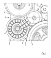
- a friction gear 3 is provided for Auxiliary unit 4 arranged outside the area of the belt drive 1. This is preferably a coolant pump for the cooling circuit Liquid-cooled internal combustion engine 2.
- the friction gear 3 comprises a in a wrap area of the Belt 5 of a drive wheel 6 on the crankshaft side of the internal combustion engine 2 interacting frictionally with the outside 7 of the belt 5 Friction wheel 8 and a drive wheel 9 which can be frictionally driven with the friction wheel 8 the coolant pump 4.
- the friction wheel 8 is by means of a control device 10 one at a cold start of the internal combustion engine 2 and the other at high Speeds to reduce power consumption out of engagement with the Drive wheel 9 of the coolant pump 4 controlled. Control of the friction wheel 8 is by means of a connecting the friction wheel 8 with the control device 10 Swivel arm 11 causes.
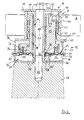
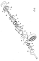
- the control device 10 further comprises a housing 16 in the form of a pot Designed receptacle 12, with a center on the bottom 16 'of the housing 16 Pipe extension 17 is arranged. This has arranged on the outer circumference first threads 18 on for a ball helical thread 19, in one 20 threaded balls secured coaxially to the tubular extension 17 in an opening 21 passing through the eccentric 13 trained second threads 22 engage.
- this is divided into a pressure chamber 24 for a pneumatic or hydraulic medium and a plunger chamber 25 for a plunger 13 'connected to the eccentric 13 by means of a piston 23 for the arrangement of the servo motor 15.
- a low-friction rotary connection 26 is provided between the plunger 13 'and the piston 23.
- the piston 23 is preferably designed as a diaphragm 27 with a transmission ring 28 arranged on the eccentric side, which, with the interposition of a rolling bearing 29 as a rotary connection 26, is in stroke connection with a guide ring 30 arranged on the eccentric tappet 13 '.
- the jacket 31 of the pot-like Housing 16 in over flanges 32, 33 with the interposition of rubber-elastic membrane 27 connectable sections 34, 35 divided.
- the membrane 27 is designed such that it over a the central opening 36 delimiting collar 37 with the centrally at the bottom 16 ' of the housing 16 arranged, the ball screw thread 19 having Pipe extension 17 tightly encloses, the collar 37 by means of a Clamping sleeve 38 is fixed to the tubular extension 17.
- the pressure chamber 24 of the servo motor 15 is preferably under vacuum applied.
- the negative pressure acts via a line 24 'with a Vacuum pump communicates.
- Pressurizing the Pressure chamber 24 is made with compressed air or hydraulically by means of lubricating oil Lubricating oil circuit of the internal combustion engine 2 possible if corresponding adapted control device 10.
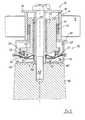
- the friction wheel 8 leading swivel arm 11 is formed from a plastic and interacts with the eye 39 Eccentric 13 together.
- a helical torsion spring 40 is located in the eye 39 arranged by the rotational bias of the eccentric 13 at activated servo motor 15 into a position via the high-helix ball thread 19 is rotated, in which the swivel arm 11 tensile loads the friction wheel 8 in operative engagement with the drive wheel 9 of the coolant pump 4 holds.
- a compact design of the control device 10 is conducive to the fact that the in the eye 39 of the swivel arm 11 against a shoulder 41 one in the Eye 39 arranged for reinforcement metal housing 42 on the one hand applied helical torsion spring 40 on the other hand in a Metal housing 42 centered with play and with the eccentric 13 via a Screw 43 connected lid 44 is held axially secured.
- Fig. 2 shows the torsion spring arranged with torsion 40 one end with the eccentric 13 and the other end with the eye 39 of the Swivel arm 11 each rotatably connected.
- This spring arrangement enables a high level of operational safety in that if the Servo motor 15 of the eccentric 13 via the ball screw 19 in a Position is rotated, by means of which the friction wheel 8 under tensile load of the Swivel arm 11 in frictional engagement with the belt 5 and Drive wheel 9 brought and held.
- the coolant pump 4 thus remains in advantageously in drive connection via the friction gear 3 with the Belt drive 1.
- a cover 45 connected to the eccentric 13 in a rotationally fixed manner provided, and on the other hand one on the tubular extension 17 overlying, rotationally secured end cover 46, the entire Control device 10 including the one carrying the friction wheel 8 Swivel arm 11 by means of a cover 44, 45, 46 and tubular extension 17th penetrating bolts 47 on a machine-side slug 48 front of the internal combustion engine 2 in the free area between the drive wheel 6 and Adjacent drive wheel 9 of the coolant pump 4 is arranged for advantageous use of space.
Landscapes
- Engineering & Computer Science (AREA)
- General Engineering & Computer Science (AREA)
- Mechanical Engineering (AREA)
- Chemical & Material Sciences (AREA)
- Combustion & Propulsion (AREA)
- Devices For Conveying Motion By Means Of Endless Flexible Members (AREA)
- Transmission Devices (AREA)
- Electromagnetic Pumps, Or The Like (AREA)
Applications Claiming Priority (2)
| Application Number | Priority Date | Filing Date | Title |
|---|---|---|---|
| DE10309061 | 2003-03-03 | ||
| DE2003109061 DE10309061A1 (de) | 2003-03-03 | 2003-03-03 | Mit einem Aggregate-Riementrieb einer Brennkraftmaschine zusammenwirkendes Reibradgetriebe für ein gesondert angeordnetes Nebenaggregat |
Publications (3)
| Publication Number | Publication Date |
|---|---|
| EP1455064A2 true EP1455064A2 (fr) | 2004-09-08 |
| EP1455064A3 EP1455064A3 (fr) | 2007-09-12 |
| EP1455064B1 EP1455064B1 (fr) | 2009-08-12 |
Family
ID=32797781
Family Applications (1)
| Application Number | Title | Priority Date | Filing Date |
|---|---|---|---|
| EP20040001909 Expired - Lifetime EP1455064B1 (fr) | 2003-03-03 | 2004-01-29 | Entraînement à courroie d'un moteur avec entraînement par friction de roue avec un contrôleur et un accessoire de moteur |
Country Status (2)
| Country | Link |
|---|---|
| EP (1) | EP1455064B1 (fr) |
| DE (2) | DE10309061A1 (fr) |
Cited By (4)
| Publication number | Priority date | Publication date | Assignee | Title |
|---|---|---|---|---|
| WO2004111494A1 (fr) * | 2003-06-12 | 2004-12-23 | Dayco Europe S.R.L. Con Unico Socio | Dispositif d'entrainement de roue d'embrayage |
| US7918758B2 (en) | 2003-04-02 | 2011-04-05 | Dayco Europe S.R.L. | Drive assembly for driving a rotary member, in particular a combustion engine water pump shaft |
| CN102767510A (zh) * | 2012-07-30 | 2012-11-07 | 长城汽车股份有限公司 | 实现车辆水泵智能启停的控制系统 |
| CN106704504A (zh) * | 2017-03-15 | 2017-05-24 | 四川田奥环保科技有限公司 | 一种自适应自动调节的摩擦轮安装驱动装置 |
Families Citing this family (2)
| Publication number | Priority date | Publication date | Assignee | Title |
|---|---|---|---|---|
| DE10346425A1 (de) | 2003-10-07 | 2005-05-19 | Bayerische Motoren Werke Ag | Reibradgetriebe für ein gesondertes Nebenaggregat einer mit riemengetriebenen Hilfsaggregaten ausgerüsteten Brennkraftmaschine |
| CN107503843A (zh) * | 2017-10-19 | 2017-12-22 | 江苏众众热能科技有限公司 | 一种汽车带传动组件 |
Citations (1)
| Publication number | Priority date | Publication date | Assignee | Title |
|---|---|---|---|---|
| DE10255075A1 (de) | 2002-11-26 | 2004-06-03 | Bayerische Motoren Werke Ag | In einem Riementrieb für Aggregate einer Brennkraftmaschine vorgesehenes Reibradgetriebe für ein gesondertes Nebenaggregat |
Family Cites Families (3)
| Publication number | Priority date | Publication date | Assignee | Title |
|---|---|---|---|---|
| DE1810126U (de) * | 1960-02-24 | 1960-04-21 | Henschel Werke G M B H | Reibradantrieb fuer hilfsantriebe an fahrzeugmotoren. |
| DE3934884A1 (de) * | 1989-10-19 | 1991-04-25 | Bayerische Motoren Werke Ag | Endloses zugmittelgetriebe einer brennkraftmaschine |
| DE4039206A1 (de) * | 1990-12-08 | 1992-06-11 | Audi Ag | Antriebsvorrichtung |
-
2003
- 2003-03-03 DE DE2003109061 patent/DE10309061A1/de not_active Withdrawn
-
2004
- 2004-01-29 EP EP20040001909 patent/EP1455064B1/fr not_active Expired - Lifetime
- 2004-01-29 DE DE200450009873 patent/DE502004009873D1/de not_active Expired - Lifetime
Patent Citations (1)
| Publication number | Priority date | Publication date | Assignee | Title |
|---|---|---|---|---|
| DE10255075A1 (de) | 2002-11-26 | 2004-06-03 | Bayerische Motoren Werke Ag | In einem Riementrieb für Aggregate einer Brennkraftmaschine vorgesehenes Reibradgetriebe für ein gesondertes Nebenaggregat |
Cited By (5)
| Publication number | Priority date | Publication date | Assignee | Title |
|---|---|---|---|---|
| US7918758B2 (en) | 2003-04-02 | 2011-04-05 | Dayco Europe S.R.L. | Drive assembly for driving a rotary member, in particular a combustion engine water pump shaft |
| EP1464870B1 (fr) * | 2003-04-02 | 2012-08-29 | DAYCO EUROPE S.r.l. | Système de propulsion pour l'entraînement de corps rotatif, en particulier pour pompe à eau d'un moteur à combustion thermique |
| WO2004111494A1 (fr) * | 2003-06-12 | 2004-12-23 | Dayco Europe S.R.L. Con Unico Socio | Dispositif d'entrainement de roue d'embrayage |
| CN102767510A (zh) * | 2012-07-30 | 2012-11-07 | 长城汽车股份有限公司 | 实现车辆水泵智能启停的控制系统 |
| CN106704504A (zh) * | 2017-03-15 | 2017-05-24 | 四川田奥环保科技有限公司 | 一种自适应自动调节的摩擦轮安装驱动装置 |
Also Published As
| Publication number | Publication date |
|---|---|
| EP1455064B1 (fr) | 2009-08-12 |
| EP1455064A3 (fr) | 2007-09-12 |
| DE10309061A1 (de) | 2004-10-14 |
| DE502004009873D1 (de) | 2009-09-24 |
Similar Documents
| Publication | Publication Date | Title |
|---|---|---|
| EP0944937B1 (fr) | Dispositif de pressage hydraulique | |
| EP0925201B1 (fr) | Dispositif d'entrainement de roue hydrostatique et mecanique | |
| DE19880317C2 (de) | Hochdruckpumpe | |
| EP1397231A1 (fr) | Outil de moulage par compression dote d'une broche destinee a la compression d'elements de couplage | |
| EP0517014A1 (fr) | Pompe à engrenages pour huile de lubrification d'un moteur à combustion interne, en particulier pour véhicules | |
| DE10055753B4 (de) | Hydrostatische Axialkolbenmaschine in Schrägscheibenbauweise mit Gleitschuhgelenken innerhalb der Bohrungen im Zylinderblock | |
| DD144884A5 (de) | Motorisch betriebener motorhammer | |
| DE3511608A1 (de) | Luftkompressor | |
| EP1244187A1 (fr) | Dispositif de pressage hydraulique et son procédé de fonctionnement | |
| EP0642430B1 (fr) | Pompe hydraulique entrainee par un moteur a combustion interne | |
| EP0533720B1 (fr) | Dispositif d'entrainement | |
| EP1455064A2 (fr) | Entraínement par friction de roue coopérant avec entraínement à courroie pour des accessoires d'un moteur, pour un accessoire de moteur arrangé séparement | |
| DE69725922T2 (de) | Hydrostatisches,stufenlos verstellbares Getriebe | |
| WO2004048808A1 (fr) | Engrenage a roue de friction dispose dans un mecanisme d'entrainement par courroie, destine aux unites d'un moteur a combustion interne et a une unite auxiliaire separee | |
| DE3622335C2 (de) | Antriebseinrichtung für Nebenaggregate einer Brennkraftmaschine | |
| DE10255079A1 (de) | Einem Aggregate-Riementrieb einer Brennkraftmaschine zugeordnetes Reibradgetriebe für ein gesondertes Nebenaggregat | |
| DE3780790T2 (de) | Hydraulisch betriebenes schiefscheibengeraet. | |
| EP0786047B1 (fr) | Dispositif d'injection de carburant et d'alimentation en lubrifiant pour moteurs a combustion interne | |
| DE3835696C2 (de) | Tragbare Presse zur Herstellung von Preßverbindungen | |
| DE10255073A1 (de) | Mit einem Reibradgetriebe kombinierter Riementrieb zum Antrieb von Aggregaten einer Brennkraftmaschine | |
| EP1092869B1 (fr) | Système de propulsion avec machine hydraulique à piston | |
| EP1464809B1 (fr) | Transmission par courroie pour des groupes auxiliaires d'un moteur à combustion interne | |
| DE69612595T2 (de) | Hydrostatisches, stufenloses Getriebe | |
| EP0395889B1 (fr) | Dispositif de serrage de pièces | |
| DE19957568B4 (de) | Anordnung mit einem Schwungrad und einer hydrostatischen Axialkolbenmaschine |
Legal Events
| Date | Code | Title | Description |
|---|---|---|---|
| PUAI | Public reference made under article 153(3) epc to a published international application that has entered the european phase |
Free format text: ORIGINAL CODE: 0009012 |
|
| AK | Designated contracting states |
Kind code of ref document: A2 Designated state(s): AT BE BG CH CY CZ DE DK EE ES FI FR GB GR HU IE IT LI LU MC NL PT RO SE SI SK TR |
|
| AX | Request for extension of the european patent |
Extension state: AL LT LV MK |
|
| PUAL | Search report despatched |
Free format text: ORIGINAL CODE: 0009013 |
|
| AK | Designated contracting states |
Kind code of ref document: A3 Designated state(s): AT BE BG CH CY CZ DE DK EE ES FI FR GB GR HU IE IT LI LU MC NL PT RO SE SI SK TR |
|
| AX | Request for extension of the european patent |
Extension state: AL LT LV MK |
|
| 17P | Request for examination filed |
Effective date: 20070928 |
|
| 17Q | First examination report despatched |
Effective date: 20071108 |
|
| AKX | Designation fees paid |
Designated state(s): DE FR GB |
|
| RTI1 | Title (correction) |
Free format text: BELT DRIVE FOR ENGINE ACCESSORIES WITH A FRICTION WHEEL DRIVE WITH A CONTROLLER AND A ACCESSORY |
|
| GRAP | Despatch of communication of intention to grant a patent |
Free format text: ORIGINAL CODE: EPIDOSNIGR1 |
|
| GRAS | Grant fee paid |
Free format text: ORIGINAL CODE: EPIDOSNIGR3 |
|
| GRAA | (expected) grant |
Free format text: ORIGINAL CODE: 0009210 |
|
| AK | Designated contracting states |
Kind code of ref document: B1 Designated state(s): DE FR GB |
|
| REG | Reference to a national code |
Ref country code: GB Ref legal event code: FG4D Free format text: NOT ENGLISH |
|
| REF | Corresponds to: |
Ref document number: 502004009873 Country of ref document: DE Date of ref document: 20090924 Kind code of ref document: P |
|
| PLBE | No opposition filed within time limit |
Free format text: ORIGINAL CODE: 0009261 |
|
| STAA | Information on the status of an ep patent application or granted ep patent |
Free format text: STATUS: NO OPPOSITION FILED WITHIN TIME LIMIT |
|
| 26N | No opposition filed |
Effective date: 20100517 |
|
| REG | Reference to a national code |
Ref country code: FR Ref legal event code: PLFP Year of fee payment: 13 |
|
| REG | Reference to a national code |
Ref country code: FR Ref legal event code: PLFP Year of fee payment: 14 |
|
| REG | Reference to a national code |
Ref country code: FR Ref legal event code: PLFP Year of fee payment: 15 |
|
| PGFP | Annual fee paid to national office [announced via postgrant information from national office to epo] |
Ref country code: FR Payment date: 20230123 Year of fee payment: 20 |
|
| PGFP | Annual fee paid to national office [announced via postgrant information from national office to epo] |
Ref country code: GB Payment date: 20230124 Year of fee payment: 20 Ref country code: DE Payment date: 20230110 Year of fee payment: 20 |
|
| P01 | Opt-out of the competence of the unified patent court (upc) registered |
Effective date: 20230503 |
|
| REG | Reference to a national code |
Ref country code: DE Ref legal event code: R071 Ref document number: 502004009873 Country of ref document: DE |
|
| REG | Reference to a national code |
Ref country code: GB Ref legal event code: PE20 Expiry date: 20240128 |
|
| PG25 | Lapsed in a contracting state [announced via postgrant information from national office to epo] |
Ref country code: GB Free format text: LAPSE BECAUSE OF EXPIRATION OF PROTECTION Effective date: 20240128 |