EP1455077A2 - Procédé d'exploitation d'un système d'alimentation de carburant pour un moteur LPG - Google Patents
Procédé d'exploitation d'un système d'alimentation de carburant pour un moteur LPG Download PDFInfo
- Publication number
- EP1455077A2 EP1455077A2 EP04005172A EP04005172A EP1455077A2 EP 1455077 A2 EP1455077 A2 EP 1455077A2 EP 04005172 A EP04005172 A EP 04005172A EP 04005172 A EP04005172 A EP 04005172A EP 1455077 A2 EP1455077 A2 EP 1455077A2
- Authority
- EP
- European Patent Office
- Prior art keywords
- fuel system
- combustion engine
- internal combustion
- heating
- heating device
- Prior art date
- Legal status (The legal status is an assumption and is not a legal conclusion. Google has not performed a legal analysis and makes no representation as to the accuracy of the status listed.)
- Granted
Links
- 239000000446 fuel Substances 0.000 title claims abstract description 45
- 238000000034 method Methods 0.000 title claims abstract description 22
- 238000010438 heat treatment Methods 0.000 claims abstract description 72
- 238000002485 combustion reaction Methods 0.000 claims abstract description 59
- 239000003380 propellant Substances 0.000 claims abstract description 26
- 239000000498 cooling water Substances 0.000 claims abstract description 7
- 239000010720 hydraulic oil Substances 0.000 claims abstract description 4
- 239000007858 starting material Substances 0.000 claims description 7
- 230000001419 dependent effect Effects 0.000 abstract description 2
- 239000007789 gas Substances 0.000 description 23
- 238000002347 injection Methods 0.000 description 5
- 239000007924 injection Substances 0.000 description 5
- 239000003915 liquefied petroleum gas Substances 0.000 description 4
- 239000007788 liquid Substances 0.000 description 4
- ATUOYWHBWRKTHZ-UHFFFAOYSA-N Propane Chemical compound CCC ATUOYWHBWRKTHZ-UHFFFAOYSA-N 0.000 description 2
- 238000001704 evaporation Methods 0.000 description 2
- 230000008020 evaporation Effects 0.000 description 2
- 239000007792 gaseous phase Substances 0.000 description 2
- 239000001273 butane Substances 0.000 description 1
- 239000002826 coolant Substances 0.000 description 1
- 238000001816 cooling Methods 0.000 description 1
- 238000010586 diagram Methods 0.000 description 1
- 238000005485 electric heating Methods 0.000 description 1
- 230000005611 electricity Effects 0.000 description 1
- 239000002828 fuel tank Substances 0.000 description 1
- IJDNQMDRQITEOD-UHFFFAOYSA-N n-butane Chemical compound CCCC IJDNQMDRQITEOD-UHFFFAOYSA-N 0.000 description 1
- OFBQJSOFQDEBGM-UHFFFAOYSA-N n-pentane Natural products CCCCC OFBQJSOFQDEBGM-UHFFFAOYSA-N 0.000 description 1
- 239000001294 propane Substances 0.000 description 1
- 230000001960 triggered effect Effects 0.000 description 1
- 238000011144 upstream manufacturing Methods 0.000 description 1
- 239000006200 vaporizer Substances 0.000 description 1
Images

Classifications
-
- F—MECHANICAL ENGINEERING; LIGHTING; HEATING; WEAPONS; BLASTING
- F02—COMBUSTION ENGINES; HOT-GAS OR COMBUSTION-PRODUCT ENGINE PLANTS
- F02M—SUPPLYING COMBUSTION ENGINES IN GENERAL WITH COMBUSTIBLE MIXTURES OR CONSTITUENTS THEREOF
- F02M21/00—Apparatus for supplying engines with non-liquid fuels, e.g. gaseous fuels stored in liquid form
- F02M21/02—Apparatus for supplying engines with non-liquid fuels, e.g. gaseous fuels stored in liquid form for gaseous fuels
- F02M21/0218—Details on the gaseous fuel supply system, e.g. tanks, valves, pipes, pumps, rails, injectors or mixers
- F02M21/023—Valves; Pressure or flow regulators in the fuel supply or return system
- F02M21/0242—Shut-off valves; Check valves; Safety valves; Pressure relief valves
-
- F—MECHANICAL ENGINEERING; LIGHTING; HEATING; WEAPONS; BLASTING
- F02—COMBUSTION ENGINES; HOT-GAS OR COMBUSTION-PRODUCT ENGINE PLANTS
- F02D—CONTROLLING COMBUSTION ENGINES
- F02D19/00—Controlling engines characterised by their use of non-liquid fuels, pluralities of fuels, or non-fuel substances added to the combustible mixtures
- F02D19/02—Controlling engines characterised by their use of non-liquid fuels, pluralities of fuels, or non-fuel substances added to the combustible mixtures peculiar to engines working with gaseous fuels
- F02D19/021—Control of components of the fuel supply system
- F02D19/022—Control of components of the fuel supply system to adjust the fuel pressure, temperature or composition
-
- F—MECHANICAL ENGINEERING; LIGHTING; HEATING; WEAPONS; BLASTING
- F02—COMBUSTION ENGINES; HOT-GAS OR COMBUSTION-PRODUCT ENGINE PLANTS
- F02M—SUPPLYING COMBUSTION ENGINES IN GENERAL WITH COMBUSTIBLE MIXTURES OR CONSTITUENTS THEREOF
- F02M21/00—Apparatus for supplying engines with non-liquid fuels, e.g. gaseous fuels stored in liquid form
- F02M21/02—Apparatus for supplying engines with non-liquid fuels, e.g. gaseous fuels stored in liquid form for gaseous fuels
- F02M21/06—Apparatus for de-liquefying, e.g. by heating
-
- F—MECHANICAL ENGINEERING; LIGHTING; HEATING; WEAPONS; BLASTING
- F02—COMBUSTION ENGINES; HOT-GAS OR COMBUSTION-PRODUCT ENGINE PLANTS
- F02D—CONTROLLING COMBUSTION ENGINES
- F02D19/00—Controlling engines characterised by their use of non-liquid fuels, pluralities of fuels, or non-fuel substances added to the combustible mixtures
- F02D19/02—Controlling engines characterised by their use of non-liquid fuels, pluralities of fuels, or non-fuel substances added to the combustible mixtures peculiar to engines working with gaseous fuels
- F02D19/026—Measuring or estimating parameters related to the fuel supply system
- F02D19/027—Determining the fuel pressure, temperature or volume flow, the fuel tank fill level or a valve position
- F02D19/028—Determining the fuel pressure, temperature or volume flow, the fuel tank fill level or a valve position by estimation, i.e. without using direct measured parameter of a corresponding sensor
-
- F—MECHANICAL ENGINEERING; LIGHTING; HEATING; WEAPONS; BLASTING
- F02—COMBUSTION ENGINES; HOT-GAS OR COMBUSTION-PRODUCT ENGINE PLANTS
- F02M—SUPPLYING COMBUSTION ENGINES IN GENERAL WITH COMBUSTIBLE MIXTURES OR CONSTITUENTS THEREOF
- F02M21/00—Apparatus for supplying engines with non-liquid fuels, e.g. gaseous fuels stored in liquid form
- F02M21/02—Apparatus for supplying engines with non-liquid fuels, e.g. gaseous fuels stored in liquid form for gaseous fuels
- F02M21/0203—Apparatus for supplying engines with non-liquid fuels, e.g. gaseous fuels stored in liquid form for gaseous fuels characterised by the type of gaseous fuel
- F02M21/0209—Hydrocarbon fuels, e.g. methane or acetylene
- F02M21/0212—Hydrocarbon fuels, e.g. methane or acetylene comprising at least 3 C-Atoms, e.g. liquefied petroleum gas [LPG], propane or butane
-
- Y—GENERAL TAGGING OF NEW TECHNOLOGICAL DEVELOPMENTS; GENERAL TAGGING OF CROSS-SECTIONAL TECHNOLOGIES SPANNING OVER SEVERAL SECTIONS OF THE IPC; TECHNICAL SUBJECTS COVERED BY FORMER USPC CROSS-REFERENCE ART COLLECTIONS [XRACs] AND DIGESTS
- Y02—TECHNOLOGIES OR APPLICATIONS FOR MITIGATION OR ADAPTATION AGAINST CLIMATE CHANGE
- Y02T—CLIMATE CHANGE MITIGATION TECHNOLOGIES RELATED TO TRANSPORTATION
- Y02T10/00—Road transport of goods or passengers
- Y02T10/10—Internal combustion engine [ICE] based vehicles
- Y02T10/30—Use of alternative fuels, e.g. biofuels
Definitions
- the invention relates to a method for operating a fuel system for a Propellant powered internal combustion engine, the fuel system at least one electrically controllable shut-off valve and at least one electrically operated Has heating device for the propellant gas.
- Combustion engines powered by propellant gas are often used in industrial trucks such as. Forklift trucks, but also used in passenger cars. That for this Commonly used propellant gas is often used as liquid gas or as LPG (liquid petroleum gas) denotes and mainly consists of propane and / or Butane.
- LPG liquid petroleum gas
- the fuel system of such an internal combustion engine comprises a Pressurized gas bottle or fuel tank designed as a pressure tank, an evaporator and a shut-off valve upstream of the evaporator.
- a Pressurized gas bottle or fuel tank designed as a pressure tank, an evaporator and a shut-off valve upstream of the evaporator.
- the vaporizer that becomes expanded propellant gas is released into a gaseous state, wherein thermal energy is supplied to the propellant gas. After long operation of the Internal combustion engine usually does this by means of the coolant of the Combustion engine.
- the Evaporator can also include the function of a pressure regulator, so that Propellant gas at the outlet of the evaporator in a gaseous state with a defined Pressure is available.
- Another component downstream of the evaporator The fuel system is either a mixer, which functions in terms of its function Carburetor corresponds to a petrol engine, or an injection system.
- the invention has for its object a method for operating a To provide fuel system that accumulates in any operating situation of critical amounts of liquid propellant gas safely prevented behind the evaporator.
- this object is achieved by the following method steps: When the internal combustion engine is switched on, a signal for switching on the Heater generated; when the heater is turned on at least once determined a heating requirement of the fuel system; depending on that Heating requirement of the fuel system, a delay time is determined, after which the Shut-off valve is opened after switching on the heating device.
- the Switching on the internal combustion engine is triggered by an operator, for example by turning an ignition key or pressing one Start button. After switching on the internal combustion engine with the started automatically running method according to the invention. Doing so first turned on the electric heater of the fuel system. With this can, for example, an evaporator and an injection manifold Fuel system to be preheated.
- a Delay time determines after which the fuel supply by opening the Shut-off valve begins. The delay time thus corresponds to a preheating time Fuel System.
- the heating requirement of the fuel system is measured depending on a Temperature value of the internal combustion engine and / or depending on one measured temperature value independent of the internal combustion engine and / or in Depends on the current flowing through the heating device.
- Temperature value of the internal combustion engine comes, for example Cooling water temperature in question.
- Temperature value can be, for example, the temperature of a hydraulic system Vehicle are used when fuel system and internal combustion engine part a working machine having a hydraulic unit. Based on this With the two measured temperature values, the operating status of the Internal combustion engine and the fuel system, their temperature level and that Clearly estimate the temperature level of the surroundings, although anyway existing temperature sensors can be used. It would be possible however, also to provide at least one additional temperature sensor.
- a Another input variable for determining the heating requirement can be the heating device flowing current be that of the battery voltage, but also of the Temperature of the heater itself depends. This is particularly the case if the heater has PTC heating elements, the internal resistance of which increased with increasing temperature. Checking the flow through the heater Electricity can serve to clarify security. Alternatively, this can also be done Signal of a temperature sensor can be used.
- the electrical heating device is also switched off automatically. there is exceeded when a predetermined limit for the current temperature is exceeded Fuel system, which is determined from the heating requirements of the fuel system, and / or when falling below a predetermined limit for the heating device flowing current and / or when a defined maximum is exceeded Operating time of the heating device a signal to switch off the heating device generated. The overall power requirement of the heating device is thus limited. At the same time it is ensured that there is no unnecessary heating when the fuel system is already sufficiently warm.
- the above-mentioned delay time is additionally dependent on the Heater flowing through current and / or depending on the voltage a vehicle battery determined. This is used to calculate the delay time also sizes from which the instantaneous heating power of the electrical Heater can be derived.
- the elapse of the delay time is determined by a signal generator, for example by a lamp appears. This tells the operator that the Internal combustion engine can now be started by pressing the starter.
- the shut-off valve is initially only for a short time open the duration of the cycle time, so that only a limited amount of propellant gas in the Evaporator is let in. With a warm start of the internal combustion engine, the Cycle time to be set to zero, which then requires the shut-off valve to open all the time causes.
- the shut-off valve is opened again when the speed has passed after the cycle time of the internal combustion engine exceeds the speed of the starter. Only when the Combustion engine runs by itself, so propellant gas is continuously supplied.
- the shut-off valve remains open if, after a waiting period, the speed of the Internal combustion engine exceeds a defined start release speed.
- the Starting release speed is not reached, for example, if the Internal combustion engine does not run on all cylinders. In this case it will The shut-off valve is closed again so that the start attempt is aborted.
- the aim is to prevent the Parts of the fuel system downstream of the shut-off valve remain propellant gas. This is achieved by switching off the gas shortage, whereby when the running internal combustion engine generates a signal to close the shut-off valve is the run-on time of the internal combustion engine after closing the Shut-off valve is detected and an error signal is generated when the lag time exceeds a predetermined limit. This way the functionality of the shut-off valve should be checked because the overrun time is too long jamming shut-off valve indicates. If an error signal is generated, if necessary additionally depending on a temperature value, a restart of the internal combustion engine can be prevented.
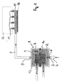
- FIG. 1 shows a fuel system for a liquid gas (LPG) operated Combustion engine.
- An evaporator 1 has a first evaporator chamber 2 and one second evaporator chamber 3.
- a pressure vessel, not shown, for the propellant gas is via an electrically controllable shut-off valve 4 to an input 5 of the Evaporator 1 connected.
- In the area of the entrance 5 there is a first one Valve 6, on which the propellant gas is expanded and at least partially the gaseous phase passes.
- Via second valve 7, the propellant gas enters second evaporator chamber 3 and goes almost completely into the gaseous Phase over.
- An outlet 8 arranged on the second evaporator chamber 3 connects the evaporator 1 to a collective injection line 10 via a line 9.
- Valves 11 are arranged on the collective injection line 10, via which the Propellant gas directly or indirectly into the combustion chambers of an air intake duct Internal combustion engine 12 is injected.
- the propellant takes thermal energy from its surroundings on the evaporator 1 by means of a first heater 13 and a second Heater 14 is supplied.
- the first heating device 13 is connected to one Cooling circuit of the internal combustion engine 12 coupled.
- the second heater 14 is heated with electrical energy, so it can be used regardless of the state of the Internal combustion engine 12 are operated. From the second heater 14 Heat is generated by means of a PTC heating element, the temperature of which is independent regulates to a preset value.
- a third heating device 16 is used for Heating the collective injection line 10 and is also with a PTC heating element equipped.
- the operator gives the signal to switch on the internal combustion engine. This is done, for example, by turning an ignition key or by pressing a start button.
- the electrically operated heating device (FIG. 1, items 14, 16) of the fuel system is also switched on automatically.
- a computing element 22 is informed of the electric current I heating currently flowing through the heating device (FIG. 1, items 14, 16), wherein l heater is composed of the flows through the first and second heaters (14 and 16).
- Further input variables for determining the heating requirement ⁇ reference are the current cooling water temperature T cooling water engine of the internal combustion engine and / or the current hydraulic oil temperature T hydraulic oil of a hydraulic system and / or an additional temperature sensor.
- the heating device (FIG. 1, items 14, 16) is switched off again at the time 24. This happens when a calculated temperature value of the evaporator T reference derived from the heating requirement ⁇ reference is greater than a limit y which corresponds to the calculated temperature value of the heating element (FIG. 1, items 14, 16) itself. Likewise, the heating device is switched off automatically (FIG. 1, items 14, 16) when the current l heating falls below a predetermined limit of z amperes.
- the value z can be preset, or it can be defined as a variable that depends on the battery voltage, for example.
- the heating is also switched off when a maximum heating time with the engine running or a maximum heating time with the engine stopped is exceeded.
- a delay time for the opening of the shut-off valve (FIG. 1, item 4) is calculated in the computing element 25.
- Further input variables for calculating the delay time are the battery voltage U battery of the vehicle battery and the current I heating .
- the delay time thus corresponds to the preheating time of the fuel system by means of the electrical heating element until the internal combustion engine can be started.
- a cycle time t cycles is determined in the computing element 25, which specifies how long the shut-off valve (FIG. 1, item 4) is opened for the first time.
- step 30 A further query is then made in step 30 to determine whether the internal combustion engine has reached its idling speed. For this purpose, the current engine speed n engine is compared with a defined start release speed n start release . If the engine speed n engine is higher, the shut-off valve (Fig. 1, item 4) remains open according to step 31.
- the fuel system remains in this state until the operator generates a signal for switching off the internal combustion engine at time 32, for example by turning the ignition key back or by pressing a stop button.
- a low-gas shutdown of the internal combustion engine is initiated, the shut-off valve (FIG. 1, item 4) being closed with step 33.
- the lag time t n engine of the internal combustion engine is then detected in the link 34 and compared in step 35 with a defined limit value w. If the run-on time t n motor is greater than w, this indicates that the shut-off valve is not fully closed and thus undesirable propellant gas flows into the evaporator.
- step 36 an error message is generated in step 36 and the internal combustion engine is prevented from being switched on again depending on a reference temperature , for example T engine cooling water , since the propellant gas flowing in recondenses behind the evaporator and an unsafe operating state could thus arise.
- the internal combustion engine can then be started again when the T cooling water engine reaches or falls below the stored comparison value v.
Landscapes
- Engineering & Computer Science (AREA)
- Chemical & Material Sciences (AREA)
- Combustion & Propulsion (AREA)
- Mechanical Engineering (AREA)
- General Engineering & Computer Science (AREA)
- Chemical Kinetics & Catalysis (AREA)
- General Chemical & Material Sciences (AREA)
- Oil, Petroleum & Natural Gas (AREA)
- Output Control And Ontrol Of Special Type Engine (AREA)
- Combined Controls Of Internal Combustion Engines (AREA)
- Electrical Control Of Air Or Fuel Supplied To Internal-Combustion Engine (AREA)
Applications Claiming Priority (2)
| Application Number | Priority Date | Filing Date | Title |
|---|---|---|---|
| DE10310151 | 2003-03-07 | ||
| DE10310151A DE10310151A1 (de) | 2003-03-07 | 2003-03-07 | Verfahren zum Betreiben einer Kraftstoffanlage für einen LPG-Motor |
Publications (3)
| Publication Number | Publication Date |
|---|---|
| EP1455077A2 true EP1455077A2 (fr) | 2004-09-08 |
| EP1455077A3 EP1455077A3 (fr) | 2010-03-31 |
| EP1455077B1 EP1455077B1 (fr) | 2011-12-14 |
Family
ID=32797885
Family Applications (1)
| Application Number | Title | Priority Date | Filing Date |
|---|---|---|---|
| EP04005172A Expired - Lifetime EP1455077B1 (fr) | 2003-03-07 | 2004-03-04 | Procédé d'exploitation d'un système d'alimentation de carburant pour un moteur GPL |
Country Status (5)
| Country | Link |
|---|---|
| US (1) | US7017559B2 (fr) |
| EP (1) | EP1455077B1 (fr) |
| JP (1) | JP4416539B2 (fr) |
| AT (1) | ATE537347T1 (fr) |
| DE (1) | DE10310151A1 (fr) |
Cited By (9)
| Publication number | Priority date | Publication date | Assignee | Title |
|---|---|---|---|---|
| EP2228526A3 (fr) * | 2009-03-12 | 2013-07-31 | Jungheinrich Aktiengesellschaft | Véhicule, notamment chariot de manutention, doté d'un moteur à combustion de gaz |
| WO2014070027A1 (fr) | 2012-10-31 | 2014-05-08 | Spółka Akcyjna AC | Réchauffeur d'appoint de démarrage pour le régulateur de pression et vaporiseur dans les installations automobiles d'alimentation en gaz et procédé de réchauffage d'appoint de démarrage dans les installations automobiles d'alimentation en gaz |
| ITUB20152802A1 (it) * | 2015-08-03 | 2017-02-03 | Metatronix S R L | Sistema per il condizionamento termico di un combustibile gassoso |
| ITUB20152789A1 (it) * | 2015-08-03 | 2017-02-03 | Metatronix S R L | Sistema per il condizionamento termico di un combustibile gassoso |
| DE102016124835A1 (de) | 2016-12-19 | 2017-02-23 | Fev Gmbh | Verfahren zum Heizen eines Einspritzventils |
| DE102017100025A1 (de) | 2016-01-11 | 2017-07-13 | FEV Europe GmbH | Verfahren zur Umschaltung einer Kraftstoffversorgung einer Brennkraftmaschine |
| WO2017157754A1 (fr) * | 2016-03-18 | 2017-09-21 | Volkswagen Aktiengesellschaft | Moteur à combustion interne et procédé permettant de faire fonctionner un moteur à combustion interne |
| WO2018219604A1 (fr) * | 2017-05-27 | 2018-12-06 | Robert Bosch Gmbh | Dispositif d'injection de carburant et procédé de chauffage de carburant |
| CN109139327A (zh) * | 2018-09-29 | 2019-01-04 | 南京汽车集团有限公司 | 一种柴油动力车辆低压油路供给系统及其控制方法 |
Families Citing this family (6)
| Publication number | Priority date | Publication date | Assignee | Title |
|---|---|---|---|---|
| DE102006060307A1 (de) * | 2006-12-20 | 2008-06-26 | Robert Bosch Gmbh | Verfahren zum Betreiben einer Abschalteinrichtung für eine Vorrichtung, insbesondere eine Brennkraftmaschine und/oder eine elektrische Maschine, sowie Abschalteinrichtung |
| DE102008024561B4 (de) * | 2008-05-21 | 2015-01-08 | Vialle Alternative Fuel Systems B.V. | Verfahren zum Betreiben einer Verbrennungskraftmaschine |
| WO2010016903A2 (fr) * | 2008-08-06 | 2010-02-11 | Keith Long | Commande d’injection de propane pour moteurs à combustion interne à essence ou à combustible gazeux |
| US20110214644A1 (en) * | 2010-03-05 | 2011-09-08 | Woodward, Inc. | Cold-Start Fuel Control System |
| US9556845B2 (en) * | 2013-03-12 | 2017-01-31 | Ecomotors, Inc. | Enhanced engine performance with fuel temperature control |
| CN106523194A (zh) * | 2016-10-12 | 2017-03-22 | 成都九门科技有限公司 | 一种发动机系统及控制方法 |
Family Cites Families (33)
| Publication number | Priority date | Publication date | Assignee | Title |
|---|---|---|---|---|
| US5092281A (en) * | 1988-07-26 | 1992-03-03 | Kabushiki Kaisha Toyoda Jidoshokki Seisakusho | Hydrogen engine system |
| GB8918553D0 (en) * | 1989-08-15 | 1989-09-27 | Digital Equipment Int | Message control system |
| US5076245A (en) * | 1990-08-01 | 1991-12-31 | David P. Ward | Fuel pressure control system for gaseous fuel engines |
| US5758257A (en) * | 1994-11-29 | 1998-05-26 | Herz; Frederick | System and method for scheduling broadcast of and access to video programs and other data using customer profiles |
| US5619648A (en) * | 1994-11-30 | 1997-04-08 | Lucent Technologies Inc. | Message filtering techniques |
| US5638487A (en) * | 1994-12-30 | 1997-06-10 | Purespeech, Inc. | Automatic speech recognition |
| US5845077A (en) * | 1995-11-27 | 1998-12-01 | Microsoft Corporation | Method and system for identifying and obtaining computer software from a remote computer |
| US5704017A (en) * | 1996-02-16 | 1997-12-30 | Microsoft Corporation | Collaborative filtering utilizing a belief network |
| NL1003941C2 (nl) * | 1996-09-02 | 1998-03-11 | Vialle Bv | Brandstofinspuitinrichting voor een inwendige verbrandingsmotor. |
| US5905859A (en) * | 1997-01-09 | 1999-05-18 | International Business Machines Corporation | Managed network device security method and apparatus |
| US5805801A (en) * | 1997-01-09 | 1998-09-08 | International Business Machines Corporation | System and method for detecting and preventing security |
| FR2764002B3 (fr) * | 1997-06-03 | 1999-07-16 | Gennaro Antoine Di | Systeme de vaporisateur de gaz de petrole liquefie chauffe par l'huile de graissage du moteur |
| JPH1113548A (ja) * | 1997-06-23 | 1999-01-19 | Honda Motor Co Ltd | ガス燃料エンジン用レギュレータ |
| US6003027A (en) * | 1997-11-21 | 1999-12-14 | International Business Machines Corporation | System and method for determining confidence levels for the results of a categorization system |
| US6023723A (en) * | 1997-12-22 | 2000-02-08 | Accepted Marketing, Inc. | Method and system for filtering unwanted junk e-mail utilizing a plurality of filtering mechanisms |
| US6308273B1 (en) * | 1998-06-12 | 2001-10-23 | Microsoft Corporation | Method and system of security location discrimination |
| US6434600B2 (en) * | 1998-09-15 | 2002-08-13 | Microsoft Corporation | Methods and systems for securely delivering electronic mail to hosts having dynamic IP addresses |
| GB2343529B (en) * | 1998-11-07 | 2003-06-11 | Ibm | Filtering incoming e-mail |
| US6266692B1 (en) * | 1999-01-04 | 2001-07-24 | International Business Machines Corporation | Method for blocking all unwanted e-mail (SPAM) using a header-based password |
| US6424997B1 (en) * | 1999-01-27 | 2002-07-23 | International Business Machines Corporation | Machine learning based electronic messaging system |
| US6370526B1 (en) * | 1999-05-18 | 2002-04-09 | International Business Machines Corporation | Self-adaptive method and system for providing a user-preferred ranking order of object sets |
| US6592627B1 (en) * | 1999-06-10 | 2003-07-15 | International Business Machines Corporation | System and method for organizing repositories of semi-structured documents such as email |
| US6728690B1 (en) * | 1999-11-23 | 2004-04-27 | Microsoft Corporation | Classification system trainer employing maximum margin back-propagation with probabilistic outputs |
| US6633855B1 (en) * | 2000-01-06 | 2003-10-14 | International Business Machines Corporation | Method, system, and program for filtering content using neural networks |
| US6684201B1 (en) * | 2000-03-31 | 2004-01-27 | Microsoft Corporation | Linguistic disambiguation system and method using string-based pattern training to learn to resolve ambiguity sites |
| CA2409920C (fr) * | 2000-06-22 | 2013-05-14 | Microsoft Corporation | Plate-forme de services informatiques distribuee |
| US6779021B1 (en) * | 2000-07-28 | 2004-08-17 | International Business Machines Corporation | Method and system for predicting and managing undesirable electronic mail |
| US7188106B2 (en) * | 2001-05-01 | 2007-03-06 | International Business Machines Corporation | System and method for aggregating ranking results from various sources to improve the results of web searching |
| US7363490B2 (en) * | 2002-09-12 | 2008-04-22 | International Business Machines Corporation | Method and system for selective email acceptance via encoded email identifiers |
| US7149801B2 (en) * | 2002-11-08 | 2006-12-12 | Microsoft Corporation | Memory bound functions for spam deterrence and the like |
| US7533148B2 (en) * | 2003-01-09 | 2009-05-12 | Microsoft Corporation | Framework to enable integration of anti-spam technologies |
| US7171450B2 (en) * | 2003-01-09 | 2007-01-30 | Microsoft Corporation | Framework to enable integration of anti-spam technologies |
| AU2004205881B2 (en) * | 2003-01-15 | 2010-02-25 | Philip Morris Products S.A. | Internal combustion engine transient fuel control |
-
2003
- 2003-03-07 DE DE10310151A patent/DE10310151A1/de not_active Withdrawn
-
2004
- 2004-03-04 AT AT04005172T patent/ATE537347T1/de active
- 2004-03-04 EP EP04005172A patent/EP1455077B1/fr not_active Expired - Lifetime
- 2004-03-05 JP JP2004061902A patent/JP4416539B2/ja not_active Expired - Fee Related
- 2004-03-05 US US10/794,574 patent/US7017559B2/en not_active Expired - Fee Related
Cited By (13)
| Publication number | Priority date | Publication date | Assignee | Title |
|---|---|---|---|---|
| EP2228526A3 (fr) * | 2009-03-12 | 2013-07-31 | Jungheinrich Aktiengesellschaft | Véhicule, notamment chariot de manutention, doté d'un moteur à combustion de gaz |
| WO2014070027A1 (fr) | 2012-10-31 | 2014-05-08 | Spółka Akcyjna AC | Réchauffeur d'appoint de démarrage pour le régulateur de pression et vaporiseur dans les installations automobiles d'alimentation en gaz et procédé de réchauffage d'appoint de démarrage dans les installations automobiles d'alimentation en gaz |
| ITUB20152802A1 (it) * | 2015-08-03 | 2017-02-03 | Metatronix S R L | Sistema per il condizionamento termico di un combustibile gassoso |
| ITUB20152789A1 (it) * | 2015-08-03 | 2017-02-03 | Metatronix S R L | Sistema per il condizionamento termico di un combustibile gassoso |
| EP3128166A1 (fr) * | 2015-08-03 | 2017-02-08 | Metatronix S.r.l. | Système de conditionnement thermique d'un combustible gazeux |
| DE102017100025A1 (de) | 2016-01-11 | 2017-07-13 | FEV Europe GmbH | Verfahren zur Umschaltung einer Kraftstoffversorgung einer Brennkraftmaschine |
| WO2017157754A1 (fr) * | 2016-03-18 | 2017-09-21 | Volkswagen Aktiengesellschaft | Moteur à combustion interne et procédé permettant de faire fonctionner un moteur à combustion interne |
| CN108779742A (zh) * | 2016-03-18 | 2018-11-09 | 大众汽车有限公司 | 内燃机和用于运行内燃机的方法 |
| EP3430254B1 (fr) * | 2016-03-18 | 2024-05-08 | Volkswagen Aktiengesellschaft | Moteur à combustion interne et procédé permettant de faire fonctionner un moteur à combustion interne |
| DE102016124835A1 (de) | 2016-12-19 | 2017-02-23 | Fev Gmbh | Verfahren zum Heizen eines Einspritzventils |
| DE102017129386A1 (de) | 2016-12-19 | 2018-02-08 | FEV Europe GmbH | Verfahren zum Heizen eines Einspritzventils |
| WO2018219604A1 (fr) * | 2017-05-27 | 2018-12-06 | Robert Bosch Gmbh | Dispositif d'injection de carburant et procédé de chauffage de carburant |
| CN109139327A (zh) * | 2018-09-29 | 2019-01-04 | 南京汽车集团有限公司 | 一种柴油动力车辆低压油路供给系统及其控制方法 |
Also Published As
| Publication number | Publication date |
|---|---|
| ATE537347T1 (de) | 2011-12-15 |
| JP4416539B2 (ja) | 2010-02-17 |
| EP1455077B1 (fr) | 2011-12-14 |
| US7017559B2 (en) | 2006-03-28 |
| EP1455077A3 (fr) | 2010-03-31 |
| DE10310151A1 (de) | 2004-09-16 |
| US20040231647A1 (en) | 2004-11-25 |
| JP2004270700A (ja) | 2004-09-30 |
Similar Documents
| Publication | Publication Date | Title |
|---|---|---|
| EP1418332B1 (fr) | Système d'alimentation de carburant pour un moteur LPG | |
| EP1455077B1 (fr) | Procédé d'exploitation d'un système d'alimentation de carburant pour un moteur GPL | |
| DE69207472T2 (de) | Verfahren und Vorrichtung zur Heizung einer Luftansauganlage von Verbrennungsmotoren | |
| EP3430254B1 (fr) | Moteur à combustion interne et procédé permettant de faire fonctionner un moteur à combustion interne | |
| DE3924776C2 (fr) | ||
| DE602004000501T2 (de) | Verfahren zum Erfassen eines Ausfalls oder Störung, die bei einem Verdichtungsverhältnisvariierenden Mechanismus entsteht | |
| DE102012007053B4 (de) | Verfahren zum Betreiben einer Brennkraftmaschine sowie Brennkraftmaschine | |
| EP1536967B1 (fr) | Vehicule automobile comprenant un entrainement hybride, et procede pour regler le point mort d'un entrainement hybride de vehicule automobile | |
| DE69821590T2 (de) | Brennkraftmaschine mit einem Verbrennungsgerät | |
| EP0925434A1 (fr) | Systeme d'exploitation d'un moteur a combustion interne, en particulier d'un vehicule a moteur | |
| DE19924329B4 (de) | Heizgerät für ein Kraftfahrzeug | |
| DE69721426T2 (de) | Steuervorrichtung für Abgasrückführung für eine Brennkraftmaschine mit Doppelkühlungsanlage | |
| DE10156637C1 (de) | Verfahren zur Steuerung und Regelung des Startbetriebs einer Brennkraftmaschine | |
| EP1984612A1 (fr) | Dispositif et procede pour commander au moins une bougie de prechaufage d'un vehicule automobile | |
| DE102010049713A1 (de) | Verfahren zum Betreiben eines Verdampfers für Flüssiggas und Verdampfer | |
| DE102011004514A1 (de) | Verfahren und Steuergerät zur Einstellung einer Temperatur einer Glühstiftkerze | |
| DE3736690A1 (de) | Geraet zur steuerung der verbrennung in einer heizung | |
| EP1029722B1 (fr) | Circuit de chauffage pour véhicules à moteurs | |
| DE10005520A1 (de) | Ansaugluft-Heizsystem | |
| DE102019114204A1 (de) | Verfahren zum Vorheizen von Vorkammern einer Verbrennungskraftmaschine eines Fahrzeuges mittels Heißlufteinblasung | |
| EP1674697B1 (fr) | Moteur de combustion interne et méthode d' opération avec du combustible gazéifié | |
| EP2823171B1 (fr) | Procédé de commande d'un dispositif de chauffage destiné à chauffer un élément structural, dispositif de commande et véhicule automobile comprenant un tel dispositif | |
| DE10330824B4 (de) | Motorsteuersystem | |
| EP4031761B1 (fr) | Système de démarrage à froid pour un véhicule fonctionnant au moyen de gaz comprimé et présentant une alimentation en carburant de type monocarburation | |
| DE10160529C1 (de) | Verfahren zum Steuern von emissionsrelevanten Komponenten in einem Kraftfahrzeug |
Legal Events
| Date | Code | Title | Description |
|---|---|---|---|
| PUAI | Public reference made under article 153(3) epc to a published international application that has entered the european phase |
Free format text: ORIGINAL CODE: 0009012 |
|
| AK | Designated contracting states |
Kind code of ref document: A2 Designated state(s): AT BE BG CH CY CZ DE DK EE ES FI FR GB GR HU IE IT LI LU MC NL PL PT RO SE SI SK TR |
|
| AX | Request for extension of the european patent |
Extension state: AL LT LV MK |
|
| PUAL | Search report despatched |
Free format text: ORIGINAL CODE: 0009013 |
|
| AK | Designated contracting states |
Kind code of ref document: A3 Designated state(s): AT BE BG CH CY CZ DE DK EE ES FI FR GB GR HU IE IT LI LU MC NL PL PT RO SE SI SK TR |
|
| AX | Request for extension of the european patent |
Extension state: AL LT LV MK |
|
| 17P | Request for examination filed |
Effective date: 20100802 |
|
| AKX | Designation fees paid |
Designated state(s): AT BE BG CH CY CZ DE DK EE ES FI FR GB GR HU IE IT LI LU MC NL PL PT RO SE SI SK TR |
|
| GRAP | Despatch of communication of intention to grant a patent |
Free format text: ORIGINAL CODE: EPIDOSNIGR1 |
|
| RIC1 | Information provided on ipc code assigned before grant |
Ipc: F02M 21/02 20060101AFI20110715BHEP |
|
| GRAS | Grant fee paid |
Free format text: ORIGINAL CODE: EPIDOSNIGR3 |
|
| GRAA | (expected) grant |
Free format text: ORIGINAL CODE: 0009210 |
|
| AK | Designated contracting states |
Kind code of ref document: B1 Designated state(s): AT BE BG CH CY CZ DE DK EE ES FI FR GB GR HU IE IT LI LU MC NL PL PT RO SE SI SK TR |
|
| REG | Reference to a national code |
Ref country code: GB Ref legal event code: FG4D Free format text: NOT ENGLISH |
|
| RTI1 | Title (correction) |
Free format text: METHOD FOR OPERATING A FUEL SYSTEM FOR A LPG ENGINE |
|
| REG | Reference to a national code |
Ref country code: CH Ref legal event code: EP |
|
| REG | Reference to a national code |
Ref country code: IE Ref legal event code: FG4D |
|
| REG | Reference to a national code |
Ref country code: DE Ref legal event code: R096 Ref document number: 502004013140 Country of ref document: DE Effective date: 20120209 |
|
| REG | Reference to a national code |
Ref country code: NL Ref legal event code: T3 |
|
| PG25 | Lapsed in a contracting state [announced via postgrant information from national office to epo] |
Ref country code: SI Free format text: LAPSE BECAUSE OF FAILURE TO SUBMIT A TRANSLATION OF THE DESCRIPTION OR TO PAY THE FEE WITHIN THE PRESCRIBED TIME-LIMIT Effective date: 20111214 Ref country code: SE Free format text: LAPSE BECAUSE OF FAILURE TO SUBMIT A TRANSLATION OF THE DESCRIPTION OR TO PAY THE FEE WITHIN THE PRESCRIBED TIME-LIMIT Effective date: 20111214 Ref country code: GR Free format text: LAPSE BECAUSE OF FAILURE TO SUBMIT A TRANSLATION OF THE DESCRIPTION OR TO PAY THE FEE WITHIN THE PRESCRIBED TIME-LIMIT Effective date: 20120315 |
|
| PG25 | Lapsed in a contracting state [announced via postgrant information from national office to epo] |
Ref country code: CY Free format text: LAPSE BECAUSE OF FAILURE TO SUBMIT A TRANSLATION OF THE DESCRIPTION OR TO PAY THE FEE WITHIN THE PRESCRIBED TIME-LIMIT Effective date: 20111214 |
|
| RAP2 | Party data changed (patent owner data changed or rights of a patent transferred) |
Owner name: VOLKSWAGEN AKTIENGESELLSCHAFT Owner name: STILL GMBH |
|
| REG | Reference to a national code |
Ref country code: IE Ref legal event code: FD4D |
|
| PG25 | Lapsed in a contracting state [announced via postgrant information from national office to epo] |
Ref country code: CZ Free format text: LAPSE BECAUSE OF FAILURE TO SUBMIT A TRANSLATION OF THE DESCRIPTION OR TO PAY THE FEE WITHIN THE PRESCRIBED TIME-LIMIT Effective date: 20111214 Ref country code: EE Free format text: LAPSE BECAUSE OF FAILURE TO SUBMIT A TRANSLATION OF THE DESCRIPTION OR TO PAY THE FEE WITHIN THE PRESCRIBED TIME-LIMIT Effective date: 20111214 Ref country code: BG Free format text: LAPSE BECAUSE OF FAILURE TO SUBMIT A TRANSLATION OF THE DESCRIPTION OR TO PAY THE FEE WITHIN THE PRESCRIBED TIME-LIMIT Effective date: 20120314 Ref country code: IE Free format text: LAPSE BECAUSE OF FAILURE TO SUBMIT A TRANSLATION OF THE DESCRIPTION OR TO PAY THE FEE WITHIN THE PRESCRIBED TIME-LIMIT Effective date: 20111214 Ref country code: SK Free format text: LAPSE BECAUSE OF FAILURE TO SUBMIT A TRANSLATION OF THE DESCRIPTION OR TO PAY THE FEE WITHIN THE PRESCRIBED TIME-LIMIT Effective date: 20111214 |
|
| PG25 | Lapsed in a contracting state [announced via postgrant information from national office to epo] |
Ref country code: RO Free format text: LAPSE BECAUSE OF FAILURE TO SUBMIT A TRANSLATION OF THE DESCRIPTION OR TO PAY THE FEE WITHIN THE PRESCRIBED TIME-LIMIT Effective date: 20111214 Ref country code: PT Free format text: LAPSE BECAUSE OF FAILURE TO SUBMIT A TRANSLATION OF THE DESCRIPTION OR TO PAY THE FEE WITHIN THE PRESCRIBED TIME-LIMIT Effective date: 20120416 Ref country code: PL Free format text: LAPSE BECAUSE OF FAILURE TO SUBMIT A TRANSLATION OF THE DESCRIPTION OR TO PAY THE FEE WITHIN THE PRESCRIBED TIME-LIMIT Effective date: 20111214 |
|
| BERE | Be: lapsed |
Owner name: VOLKSWAGEN AG Effective date: 20120331 Owner name: STILL G.M.B.H. Effective date: 20120331 |
|
| PLBE | No opposition filed within time limit |
Free format text: ORIGINAL CODE: 0009261 |
|
| STAA | Information on the status of an ep patent application or granted ep patent |
Free format text: STATUS: NO OPPOSITION FILED WITHIN TIME LIMIT |
|
| PG25 | Lapsed in a contracting state [announced via postgrant information from national office to epo] |
Ref country code: DK Free format text: LAPSE BECAUSE OF FAILURE TO SUBMIT A TRANSLATION OF THE DESCRIPTION OR TO PAY THE FEE WITHIN THE PRESCRIBED TIME-LIMIT Effective date: 20111214 Ref country code: MC Free format text: LAPSE BECAUSE OF NON-PAYMENT OF DUE FEES Effective date: 20120331 |
|
| REG | Reference to a national code |
Ref country code: CH Ref legal event code: PL |
|
| 26N | No opposition filed |
Effective date: 20120917 |
|
| GBPC | Gb: european patent ceased through non-payment of renewal fee |
Effective date: 20120314 |
|
| REG | Reference to a national code |
Ref country code: DE Ref legal event code: R097 Ref document number: 502004013140 Country of ref document: DE Effective date: 20120917 |
|
| PG25 | Lapsed in a contracting state [announced via postgrant information from national office to epo] |
Ref country code: CH Free format text: LAPSE BECAUSE OF NON-PAYMENT OF DUE FEES Effective date: 20120331 Ref country code: LI Free format text: LAPSE BECAUSE OF NON-PAYMENT OF DUE FEES Effective date: 20120331 Ref country code: BE Free format text: LAPSE BECAUSE OF NON-PAYMENT OF DUE FEES Effective date: 20120331 Ref country code: GB Free format text: LAPSE BECAUSE OF NON-PAYMENT OF DUE FEES Effective date: 20120314 |
|
| PG25 | Lapsed in a contracting state [announced via postgrant information from national office to epo] |
Ref country code: ES Free format text: LAPSE BECAUSE OF FAILURE TO SUBMIT A TRANSLATION OF THE DESCRIPTION OR TO PAY THE FEE WITHIN THE PRESCRIBED TIME-LIMIT Effective date: 20120325 |
|
| REG | Reference to a national code |
Ref country code: AT Ref legal event code: MM01 Ref document number: 537347 Country of ref document: AT Kind code of ref document: T Effective date: 20120304 |
|
| PG25 | Lapsed in a contracting state [announced via postgrant information from national office to epo] |
Ref country code: FI Free format text: LAPSE BECAUSE OF FAILURE TO SUBMIT A TRANSLATION OF THE DESCRIPTION OR TO PAY THE FEE WITHIN THE PRESCRIBED TIME-LIMIT Effective date: 20111214 |
|
| PG25 | Lapsed in a contracting state [announced via postgrant information from national office to epo] |
Ref country code: AT Free format text: LAPSE BECAUSE OF NON-PAYMENT OF DUE FEES Effective date: 20120304 |
|
| PG25 | Lapsed in a contracting state [announced via postgrant information from national office to epo] |
Ref country code: TR Free format text: LAPSE BECAUSE OF FAILURE TO SUBMIT A TRANSLATION OF THE DESCRIPTION OR TO PAY THE FEE WITHIN THE PRESCRIBED TIME-LIMIT Effective date: 20111214 |
|
| PG25 | Lapsed in a contracting state [announced via postgrant information from national office to epo] |
Ref country code: LU Free format text: LAPSE BECAUSE OF NON-PAYMENT OF DUE FEES Effective date: 20120304 |
|
| PG25 | Lapsed in a contracting state [announced via postgrant information from national office to epo] |
Ref country code: HU Free format text: LAPSE BECAUSE OF FAILURE TO SUBMIT A TRANSLATION OF THE DESCRIPTION OR TO PAY THE FEE WITHIN THE PRESCRIBED TIME-LIMIT Effective date: 20040304 |
|
| REG | Reference to a national code |
Ref country code: FR Ref legal event code: PLFP Year of fee payment: 12 |
|
| PGFP | Annual fee paid to national office [announced via postgrant information from national office to epo] |
Ref country code: NL Payment date: 20150323 Year of fee payment: 12 Ref country code: IT Payment date: 20150324 Year of fee payment: 12 Ref country code: DE Payment date: 20150324 Year of fee payment: 12 |
|
| PGFP | Annual fee paid to national office [announced via postgrant information from national office to epo] |
Ref country code: FR Payment date: 20150319 Year of fee payment: 12 |
|
| REG | Reference to a national code |
Ref country code: DE Ref legal event code: R119 Ref document number: 502004013140 Country of ref document: DE |
|
| REG | Reference to a national code |
Ref country code: NL Ref legal event code: MM Effective date: 20160401 |
|
| REG | Reference to a national code |
Ref country code: FR Ref legal event code: ST Effective date: 20161130 |
|
| REG | Reference to a national code |
Ref country code: DE Ref legal event code: R082 Ref document number: 502004013140 Country of ref document: DE Representative=s name: PATENTSHIP PATENTANWALTSGESELLSCHAFT MBH, DE |
|
| PG25 | Lapsed in a contracting state [announced via postgrant information from national office to epo] |
Ref country code: FR Free format text: LAPSE BECAUSE OF NON-PAYMENT OF DUE FEES Effective date: 20160331 Ref country code: NL Free format text: LAPSE BECAUSE OF NON-PAYMENT OF DUE FEES Effective date: 20160401 Ref country code: DE Free format text: LAPSE BECAUSE OF NON-PAYMENT OF DUE FEES Effective date: 20161001 |
|
| PG25 | Lapsed in a contracting state [announced via postgrant information from national office to epo] |
Ref country code: IT Free format text: LAPSE BECAUSE OF NON-PAYMENT OF DUE FEES Effective date: 20160304 |