EP1455117B1 - Stirlingmotor sowie Biomassefeuerungsanlage - Google Patents
Stirlingmotor sowie Biomassefeuerungsanlage Download PDFInfo
- Publication number
- EP1455117B1 EP1455117B1 EP20040450049 EP04450049A EP1455117B1 EP 1455117 B1 EP1455117 B1 EP 1455117B1 EP 20040450049 EP20040450049 EP 20040450049 EP 04450049 A EP04450049 A EP 04450049A EP 1455117 B1 EP1455117 B1 EP 1455117B1
- Authority
- EP
- European Patent Office
- Prior art keywords
- stirling engine
- working
- crank
- output shaft
- working pistons
- Prior art date
- Legal status (The legal status is an assumption and is not a legal conclusion. Google has not performed a legal analysis and makes no representation as to the accuracy of the status listed.)
- Expired - Lifetime
Links
- 238000002485 combustion reaction Methods 0.000 title claims description 31
- 239000002028 Biomass Substances 0.000 title claims description 20
- 230000005540 biological transmission Effects 0.000 claims description 14
- 230000033001 locomotion Effects 0.000 claims description 13
- 230000005484 gravity Effects 0.000 claims description 8
- 238000010438 heat treatment Methods 0.000 claims description 5
- 239000007789 gas Substances 0.000 description 19
- 239000003921 oil Substances 0.000 description 5
- 239000010687 lubricating oil Substances 0.000 description 3
- 239000003546 flue gas Substances 0.000 description 2
- 230000005855 radiation Effects 0.000 description 2
- UGFAIRIUMAVXCW-UHFFFAOYSA-N Carbon monoxide Chemical compound [O+]#[C-] UGFAIRIUMAVXCW-UHFFFAOYSA-N 0.000 description 1
- 239000000567 combustion gas Substances 0.000 description 1
- 238000010276 construction Methods 0.000 description 1
- 239000002826 coolant Substances 0.000 description 1
- 230000010354 integration Effects 0.000 description 1
- 238000005461 lubrication Methods 0.000 description 1
- 239000002184 metal Substances 0.000 description 1
- 230000002035 prolonged effect Effects 0.000 description 1
- 239000002918 waste heat Substances 0.000 description 1
- XLYOFNOQVPJJNP-UHFFFAOYSA-N water Substances O XLYOFNOQVPJJNP-UHFFFAOYSA-N 0.000 description 1
Images



Classifications
-
- F—MECHANICAL ENGINEERING; LIGHTING; HEATING; WEAPONS; BLASTING
- F01—MACHINES OR ENGINES IN GENERAL; ENGINE PLANTS IN GENERAL; STEAM ENGINES
- F01B—MACHINES OR ENGINES, IN GENERAL OR OF POSITIVE-DISPLACEMENT TYPE, e.g. STEAM ENGINES
- F01B9/00—Reciprocating-piston machines or engines characterised by connections between pistons and main shafts, not specific to groups F01B1/00 - F01B7/00
- F01B9/02—Reciprocating-piston machines or engines characterised by connections between pistons and main shafts, not specific to groups F01B1/00 - F01B7/00 with crankshaft
-
- F—MECHANICAL ENGINEERING; LIGHTING; HEATING; WEAPONS; BLASTING
- F02—COMBUSTION ENGINES; HOT-GAS OR COMBUSTION-PRODUCT ENGINE PLANTS
- F02G—HOT GAS OR COMBUSTION-PRODUCT POSITIVE-DISPLACEMENT ENGINE PLANTS; USE OF WASTE HEAT OF COMBUSTION ENGINES; NOT OTHERWISE PROVIDED FOR
- F02G1/00—Hot gas positive-displacement engine plants
- F02G1/04—Hot gas positive-displacement engine plants of closed-cycle type
- F02G1/043—Hot gas positive-displacement engine plants of closed-cycle type the engine being operated by expansion and contraction of a mass of working gas which is heated and cooled in one of a plurality of constantly communicating expansible chambers, e.g. Stirling cycle type engines
- F02G1/044—Hot gas positive-displacement engine plants of closed-cycle type the engine being operated by expansion and contraction of a mass of working gas which is heated and cooled in one of a plurality of constantly communicating expansible chambers, e.g. Stirling cycle type engines having at least two working members, e.g. pistons, delivering power output
-
- F—MECHANICAL ENGINEERING; LIGHTING; HEATING; WEAPONS; BLASTING
- F16—ENGINEERING ELEMENTS AND UNITS; GENERAL MEASURES FOR PRODUCING AND MAINTAINING EFFECTIVE FUNCTIONING OF MACHINES OR INSTALLATIONS; THERMAL INSULATION IN GENERAL
- F16F—SPRINGS; SHOCK-ABSORBERS; MEANS FOR DAMPING VIBRATION
- F16F15/00—Suppression of vibrations in systems; Means or arrangements for avoiding or reducing out-of-balance forces, e.g. due to motion
- F16F15/22—Compensation of inertia forces
- F16F15/26—Compensation of inertia forces of crankshaft systems using solid masses, other than the ordinary pistons, moving with the system, i.e. masses connected through a kinematic mechanism or gear system
-
- F—MECHANICAL ENGINEERING; LIGHTING; HEATING; WEAPONS; BLASTING
- F02—COMBUSTION ENGINES; HOT-GAS OR COMBUSTION-PRODUCT ENGINE PLANTS
- F02G—HOT GAS OR COMBUSTION-PRODUCT POSITIVE-DISPLACEMENT ENGINE PLANTS; USE OF WASTE HEAT OF COMBUSTION ENGINES; NOT OTHERWISE PROVIDED FOR
- F02G2244/00—Machines having two pistons
- F02G2244/50—Double acting piston machines
-
- F—MECHANICAL ENGINEERING; LIGHTING; HEATING; WEAPONS; BLASTING
- F02—COMBUSTION ENGINES; HOT-GAS OR COMBUSTION-PRODUCT ENGINE PLANTS
- F02G—HOT GAS OR COMBUSTION-PRODUCT POSITIVE-DISPLACEMENT ENGINE PLANTS; USE OF WASTE HEAT OF COMBUSTION ENGINES; NOT OTHERWISE PROVIDED FOR
- F02G2270/00—Constructional features
- F02G2270/60—Counterweights for pistons
-
- F—MECHANICAL ENGINEERING; LIGHTING; HEATING; WEAPONS; BLASTING
- F16—ENGINEERING ELEMENTS AND UNITS; GENERAL MEASURES FOR PRODUCING AND MAINTAINING EFFECTIVE FUNCTIONING OF MACHINES OR INSTALLATIONS; THERMAL INSULATION IN GENERAL
- F16H—GEARING
- F16H21/00—Gearings comprising primarily only links or levers, with or without slides
- F16H21/10—Gearings comprising primarily only links or levers, with or without slides all movement being in, or parallel to, a single plane
- F16H21/16—Gearings comprising primarily only links or levers, with or without slides all movement being in, or parallel to, a single plane for interconverting rotary motion and reciprocating motion
- F16H21/18—Crank gearings; Eccentric gearings
- F16H21/36—Crank gearings; Eccentric gearings without swinging connecting-rod, e.g. with epicyclic parallel motion, slot-and-crank motion
- F16H21/365—Crank gearings; Eccentric gearings without swinging connecting-rod, e.g. with epicyclic parallel motion, slot-and-crank motion with orbital gearing having a ratio of 2:1 between central gear and orbital gear
Definitions
- the invention relates to a Stirling engine with four mutually rotated by 90 ° arranged working piston, with a planetary gear for converting the linear movement of the working piston in a rotary motion of a common output shaft, the centers of gravity of the four working pistons are arranged in a common plane perpendicular to the axis of rotation of the output shaft, and the working pistons are mounted rotatably for straight guidance on a planetary gear designed as externally toothed crank, which rotates in at least one internally toothed ring gear. Furthermore, the invention relates to a biomass combustion plant with a combustion chamber.
- a Stirling engine of the type mentioned in which a planetary gear for implementing the linear movement of the working piston is provided in a rotational movement of an output shaft, wherein the piston rods via an outer crank on a inner crank are articulated.
- the inner crank also forms the bridge for an externally toothed planetary gear, which rotates in an internally toothed ring gear.
- both the inner crank and the outer crank are provided with at least one counterweight as balancing mass. This results in a relatively complex construction of the planetary gear with relatively large moving masses to compensate for free mass forces and moments.
- a planetary gear for an internal combustion engine in which an eccentric flywheel is provided as a counterweight to the planetary crankshaft to allow the movement of the piston from the top and bottom dead center.
- crank mechanism for an internal combustion engine in which a planetary gear is designed such that at the highest point of the combustion cycle the first crank is in the 0 ° position and the second crank is essentially in the 90 ° position so that the first and second cranks occupy a substantially 180 ° position at the end of a power stroke.
- DE 31 14 459 A1 discloses a crank mechanism for a different type of reciprocating engine is disclosed in which a planetary gear is provided for transmitting movement.
- the aim of the present invention is now to provide a Stirling engine of the type mentioned with a comparatively simple gear in which reliably a complete balance of free mass forces and moments is achieved, so that a possible vibration-free operation is possible.
- a self-starting of the engine should be possible only by supplying heat, so that the Stirling engine can be used in particular in connection with a biomass combustion system.
- crank in both end portions has an external toothing for engagement in two end-mounted internally toothed ring gears, results in a balanced bearing of the crank.
- a single pair of gears could take over the desired transmission of forces as well as the straight-line function of the piston, in which case an additional bearing would be provided to avoid jamming of the crank.
- crank between the two ring gears in the balancing weights preferably by means of needle or roller bearings, is mounted eccentrically to the output shaft.
- the balancing weights are mounted on the inside to the crank and on the outside to a rotatably mounted housing, wherein a bearing is a movable bearing and a bearing is a fixed bearing.
- the biomass combustion system according to the invention of the type mentioned above is characterized in that in the combustion chamber, a Stirling engine according to one of claims 1 to 7 is provided.
- the Stirling engine according to the invention can be integrated without additional aidssan Credred in a biomass combustion system, so that it starts automatically when heat from the combustion chamber of the biomass combustion system.
- the power of the Stirling engine is determined solely by the intensity of the heat supply, wherein this can be used, for example, to drive an electric generator.
- the flames from the combustion chamber can deliver their heat on the one hand by flame radiation and on the other hand by convection when flowing through the heater tubes, so that an exploitation of the radiant heat and a low-resistance passage of the hot flue gases is made possible.
- the slightly cooled combustion gases of the biomass combustion system can also continue after the heat transfer to the heater tubes the usual way in conventional biomass combustion systems for generating heat.
- the Stirling engine can be modularly integrated in the combustion chamber of the biomass combustion system.
- a Stirling engine 1 is shown, are arranged in the four working cylinder 2 with displaceably mounted therein working piston 3 in each case by 90 ° to each other, so that in a plan view of the Stirling engine. 1 a so-called.
- X-arrangement of the working cylinder or piston results.
- the four pistons 3, which are fastened to two double piston rods 3 ', are coupled to one another via a planetary gear 4 (cf., in particular, FIG. 4), whereby the linear movement of the working pistons 3 is converted into a rotational movement of an output shaft 5, and at the same time required for the Stirling engine phase-shifted movement between the pairs of pistons and an exact straight line of the working piston 3 in the working cylinders 2 is achieved.
- a planetary gear 4 cf., in particular, FIG. 4
- the cylinders 2 are adjoined by outer heating pipes 6, in which the working gas contained therein is heated and flows into a hot working space 2 'of the working cylinder 2.
- the heater tubes 6 each open into a regenerator 7, via which at each piston stroke in the working cylinder 2 by overflow of the gas from the hot area 2 'in the cold area 2 "(and vice versa) a part of the heat is exchanged.
- the regenerator 7 is - similar to a hollow cylinder - each plugged about in the middle of the working cylinder 2.
- Each regenerator 7 is connected to the heater tubes 6 and a heat exchanger or cooler 8 and filled with metal screens.
- the radiators 8 are each arranged in a ring around the inner, driven part of a working cylinder 2 between the regenerator 7 and a transmission housing 9 and cools this area of the working cylinder 2.
- the radiator 8 are working gas side of a tube containing the regenerator 7 with the underside of the piston 3 of the next cylinder 2 connects.
- the working gas flowing out of the regenerator 7 is cooled or the working gas flowing out of the cold region 2 "of the next cylinder 2 is heated.
- water may be provided which communicates with the Schumacherniklauf e.g. a biomass combustion plant 20 (see Fig. 6) is connected, thus enabling the use of waste heat of the engine for heating purposes.
- the transmission housing 9 is water-cooled, pressure-sealed, and contains in addition to the transmission 4 lubricating oil, a lubricating oil pump and possibly a device to regulate the gas pressure.
- the four working cylinders 2 with cooler 8, regenerator 7 and heater tubes 6 as well as an adapter for integration into a biomass combustion plant 20 (see Fig. 7) and a power generator 10 are flanged to the transmission housing.
- the piston rods 3 represent the only dynamic connection to be sealed, but which does not have to seal the full working pressure, but only the pressure difference to the transmission housing 9, which is relatively low.
- the pressure in the transmission housing 9 and in the generator 10 is approximately equal to the average pressure of the four working gas volumes, this pressure advantageously fluctuates only very slightly.
- the power generator 10 is advantageously operated grid-connected, wherein the power is supplied to the power grid according to the heat input of the furnace to the working gas.
- the engine can be operated without free inertial forces and moments, the working piston 3 on the in Figures 3 to 5 shown in detail planetary gear 4 coupled together.
- the planetary gear 4 has a crank 11, on which the two piston rods 3 'are rotatably mounted.
- the crank 11 has in its two end regions in each case an external toothing 12, 12 ', wherein instead of the lower toothing, only a bearing, for example by means of ball bearings, can be provided to absorb the force and to prevent jamming.
- the crank 11 engages with its end teeth 12, 12 'in an upper and a lower ring gear 13, 13' meshing, so that the crank 11 rotates in the ring gears 13, 13 'in the manner of a planetary gear.
- Hiebei takes the crank 11 two balancing weights 14, 14 ', so that the common center of gravity of all moving parts is located on the axis of rotation of the output shaft 5.
- the centers of gravity of the two double pistons 3 are in a plane perpendicular to the axis of rotation, a complete balance of the free mass forces and moments is achieved.
- the crank 11 is mounted in the balancing weights 14, 14 'by means of ball bearings 15, 15', wherein the balancing weights 14, 14 'are mounted radially outwardly again for a statically satisfactory bearing on the rotationally fixed gear housing 9.
- the lower ring gear 13 ' is also surrounded by an intake pipe 16, via which oil in the interior of the transmission housing 9 by means of the toothing between the crank 11 and the ring gear 13' is promoted.
- the oil is thus dusted inside the transmission case 9, so that the provision of a separate oil pump is not required.
- Fig. 5 also can be seen that the balancing weights 14, 14 'in addition to their inside storage by means of bearings 15, 15' and radially outside in the gear housing 9 by means of bearings 16, 16 'are mounted.
- a bearing 15, 15 'and 16, 16' may be provided in particular ball or needle roller bearings, wherein for a statically perfect storage either the bearings 15, 15 'as a floating bearing and the bearings 16, 16' as a fixed bearing (or vice versa) arranged are.
- the Stirling engine 1 is arranged in a combustion chamber 19 of a biomass combustion plant 20, so that the flames from the combustion chamber 19 release their heat on the one hand by flame radiation and on the other hand by convection when flowing through the heater tubes 6 of the Stirling engine 1.
Landscapes
- Engineering & Computer Science (AREA)
- General Engineering & Computer Science (AREA)
- Mechanical Engineering (AREA)
- Physics & Mathematics (AREA)
- Acoustics & Sound (AREA)
- Aviation & Aerospace Engineering (AREA)
- Chemical & Material Sciences (AREA)
- Combustion & Propulsion (AREA)
- Engine Equipment That Uses Special Cycles (AREA)
- Transmission Devices (AREA)
Description
- Die Erfindung betrifft einen Stirlingmotor mit vier jeweils um 90° zueinander verdreht angeordneten Arbeitskolben, mit einem Planetengetriebe zur Umsetzung der Linearbewegung der Arbeitskolben in eine Rotationsbewegung einer gemeinsamen Abtriebswelle, wobei die Schwerpunkte der vier Arbeitskolben in einer gemeinsamen Ebene senkrecht zur Drehachse der Abtriebswelle angeordnet sind, und die Arbeitskolben zur Geradeführung an einer als Planetenrad ausgebildeten außenverzahnten Kurbel drehbar gelagert sind, die in zumindest einem innenverzahnten Hohlrad umläuft. Weiters betrifft die Erfindung eine Biomassefeuerungsanlage mit einer Brennkammer.
- Bei Stirling- bzw. Heißgasmotoren wird Arbeitsgas - meist unter erhöhtem Druck - eingeschlossen und in einem geschlossenen Kreisprozess abwechselnd einer kalten und einer heißen Umgebung ausgesetzt, wodurch im Arbeitsgasdruck Schwankungen entstehen, die von den Kolben in mechanische Energie umgewandelt werden. Zur Umsetzung der Linearbewegung der Arbeitskolben in eine Rotationsbewegung einer Abtriebswelle sind aus dem Stand der Technik verschiedene Getriebearten, beispielsweise Schubkurbel- oder Planetengetriebe, bekannt.
- Aus der DE 43 36 976 A1 und der US 5 678 406 A ist ein Stirlingmotor der eingangs angeführten Art bekannt, bei dem ein Planetengetriebe zur Umsetzung der Linearbewegung der Arbeitskolben in eine Rotationsbewegung einer Abtriebswelle vorgesehen ist, wobei die Kolbenstangen über eine äußere Kurbel an einer inneren Kurbel angelenkt sind. Die innere Kurbel bildet zugleich den Steg für ein außenverzahntes Planetenrad, das in einem innenverzahnten Hohlrad umläuft. Um einen vollständigen Massenausgleich zu erzielen, ist es bei einem derartigen Planetengetriebe jedoch erforderlich, dass sowohl die innere Kurbel als auch die äußere Kurbel mit zumindest einem Gegengewicht als Ausgleichsmasse versehen sind. Somit ergibt sich ein vergleichsweise aufwendiger Aufbau des Planetengetriebes mit relativ großen bewegten Massen zum Ausgleich freier Massenkräfte und -momente.
- Ein weiterer Stirlingmotor ist beispielsweise aus der US 4 241 580 A bekannt, in der ein Stirlingmotor mit doppelt wirkenden Arbeitskolben geoffenbart, bei dem eine Leistungsregelung mittels variabler Räume vorgsehen ist.
- Andererseits sind herkömmliche 2- oder 4-Takt-Verbrennungsmotoren mit vier jeweils um 90° zueinander verdreht angeordneten Hubkolben bekannt. Ein derartiger Verbrennungsmotor ist beispielsweise in der DE 30 23 363 A1 gezeigt. Dieser Verbrennungsmotor weist zwei Arbeitskolbenpaare auf, die in einer Ebene senkrecht zur Drehachse von zwei gesonderten Antriebswellen seitlich zueinander versetzt angeordnet sind. Demzufolge schneiden sich deren Achsen nicht in einem Punkt der Hauptdrehachse, so dass hier freie Massenkräfte und -momente auftreten.
- Aus der DE 23 05 811 A ist ein Planetengetriebe für einen Verbrennungsmotor bekannt, bei dem als Gegengewicht zur Planetenkurbelwelle ein exzentrisches Schwungrad vorgesehen ist, um die Bewegung der Kolben aus dem oberen und unteren Totpunkt zu ermöglichen.
- Weiters ist aus der US 6,349,684 B1 ein Kurbelmechanismus für eine Brennkraftmaschine bekannt, bei der ein Planetengetriebe derart ausgebildet ist, dass sich am obersten Punkt des Verbrennungstaktes die erste Kurbel in der 0°-Position und die zweite Kurbel im Wesentlichen in der 90°-Position befinden, so dass die erste und die zweite Kurbel am Ende eines Arbeitshubs im Wesentlichen eine 180°-Stellung einnehmen.
- In der DE 31 14 459 A1 ist ein Kurbeltrieb für eine andersartige Hubkolbenmaschine geoffenbart, bei der ein Planetengetriebe zur Bewegungsübertragung vorgesehen ist.
- Ziel der vorliegenden Erfindung ist nun einen Stirlingmotor der eingangs angeführten Art mit einem vergleichsweise einfach aufgebauten Getriebe zu schaffen, bei dem zuverlässig ein vollständiger Ausgleich freier Massenkräfte und -momente erzielt wird, so dass ein möglichst vibrationsfreier Betrieb ermöglicht wird. Darüber hinaus soll ein Selbstanlaufen des Motors lediglich durch Wärmezufuhr möglich sein, so dass der Stirlingmotor insbesondere auch im Zusammenhang mit einer Biomassefeuerungsanlage verwendet werden kann.
- Dies wird bei einem Stirlingmotor der eingangs angeführten Art dadurch erzielt, dass zum vollständigen Ausgleich freier Massenkräfte und -momente lediglich der gemeinsamen Abtriebswelle zumindest zwei Ausgleichsmassen derart zugeordnet sind, dass die Arbeitskolben und die mit den Arbeitskolben mitbewegten Getriebeteile einen gemeinsamen, in der Achse der Abtriebswelle liegenden Schwerpunkt aufweisen. Der Gesamtschwerpunkt des Stirlingmotors bewegt sich somit nicht.
- Zur Erzielung eines vollständigen Ausgleichs freier Massenkräfte und -momente ist es bei dem Stirlingmotor mit jeweils um 90° zueinander verdreht angeordneten Arbeitskolben ausreichend, dass der Gesamtschwerpunkt des Getriebes auf der Drehachse der Abtriebswelle liegt, und dass beide Zylinderachsen in einer Ebene liegen, wobei hiezu die außenverzahnte Kurbel keine - wie bei der aus dem Stand der Technik bekannten Vorrichtung - Ausgleichsmassen aufweisen muss, sondern hinsichtlich einer konstruktiv einfachen Ausgestaltung des Getriebes es ausreichend ist, wenn der inneren Kurbel, d.h. der gemeinsamen Abtriebswelle, zumindest zwei Ausgleichsmassen zugeordnet sind. Durch die verkettete Anordnung der vier Arbeitsräume des Stirlingmotors, die jeweils einen Phasenwinkel von im Wesentlichen 90° zueinandern aufweisen, ergibt sich ein Gesamtabtriebsmoment, das bei jedem Drehwinkel positiv ist, so dass zudem ein Selbstanlaufen des Stirlingmotors bei Wärmezufuhr erzielt werden kann.
- Für eine konstruktiv einfache Ausgestaltung des Stirlingmotors ist es günstig, wenn doppelt wirkende Arbeitskolben vorgesehen sind.
- Weiters ist es für eine konstruktiv einfache Ausgestaltung des Stirlingmotors von Vorteil, wenn eine Ausgleichsmasse mit der Abtriebswelle einstückig ausgebildet ist.
- Für eine zuverlässige Schmierung der Getriebeteile ist es günstig, wenn durch die Verzahnung zwischen der außenverzahnten Kurbel und dem innenverzahnten Hohlrad Öl gefördert wird. Somit kann auf eine gesonderte Ölpumpe zur Umwälzung von Schmieröl verzichtet werden.
- Wenn die Kurbel in beiden Endabschnitten eine Außenverzahnung zum Eingriff in zwei endseitig angeordneten innenverzahnten Hohlrädern aufweist, ergibt sich eine ausgewogene Lagerung der Kurbel. Selbstverständlich könnte jedoch auch ein einziges Zahnradpaar die gewünschte Übertragung von Kräften als auch die Geradeführungsfunktion der Kolben übernehmen, wobei dann ein zusätzliches Lager zur Vermeidung einer Verkantung der Kurbel vorzusehen wäre.
- Um zuverlässig ein Verkanten der Kurbel zu vermeiden, ist es von Vorteil, wenn die Kurbel zwischen den beiden Hohlrädern in den Ausgleichsmassen, vorzugsweise mittels Nadel- oder Rolllagern, exzentrisch zu der Abtriebswelle gelagert ist.
- Hinsichtlich einer statisch einwandfreien Lagerung der Abtriebswelle ist es günstig, wenn die Ausgleichsmassen innenseitig zur Kurbel und außenseitig zu einem drehfest angeordneten Gehäuse gelagert sind, wobei ein Lager ein Loslager und ein Lager ein Festlager ist.
- Die erfindungsgemäße Biomassefeuerungsanlage der eingangs angeführten Art ist dadurch gekennzeichnet, dass in der Brennkammer ein Stirlingmotor nach einem der Ansprüche 1 bis 7 vorgesehen ist.
- Da bei dem erfindungsgemäßen Stirlingmotor - wie vorstehend beschrieben - keine freien Massenkräfte bzw. -momente auftreten, kann dieser ohne zusätzliche Hilfsmittel selbstanlaufend in einer Biomassefeuerungsanlage integriert werden, so dass er bei Wärmezufuhr aus der Brennkammer der Biomassefeuerungsanlage selbsttätig anläuft. Somit wird alleine über die Intensität der Wärmezufuhr die Leistung des Stirlingmotors bestimmt, wobei diese beispielsweise zum Antrieb eines Elektrogenerators herangezogen werden kann.
- Für eine effiziente Wärmeübertragung an das Arbeitsgas ist es günstig, wenn an die Arbeitszylinder des Stirlingmotors zur Erhitzung des Arbeitsgases vom Arbeitsgas durchströmte Erhitzerrohre anschließen. Hierdurch können die Flammen aus der Brennkammer ihre Wärme einerseits durch Flammstrahlung und andererseits durch Konvektion beim Durchströmen an die Erhitzerrohre abgeben, so dass eine Ausnutzung der Strahlungswärme und ein widerstandsarmer Durchtritt der heißen Rauchgase ermöglicht wird. Die geringfügig abgekühlten Verbrennungsgase der Biomassefeuerungsanlage können zudem nach der Wärmeübertragung an die Erhitzerrohre den bei konventionellen Biomassefeuerungsanlagen üblichen Weg zur Erzeugung von Wärme fortsetzen.
- Um Biomassefeuerungsanlagen auch nachträglich mit dem erfindungsgemäßen Stirlingmotor ausstatten zu können bzw. je nach Wunsch dem Stirlingmotor beim Betrieb der Biomassefeuerungsanlage zuschalten zu können, ist es günstig, wenn der Stirlingmotor modular in der Brennkammer der Biomassefeuerungsanlage integrierbar ist.
- Die Erfindung wird nachstehend anhand von einem in der Zeichnung dargestellten bevorzugten Ausführungsbeispiel, auf das sie jedoch nicht beschränkt sein soll, noch weiter erläutert. Im Einzelnen zeigen in der Zeichnung:
- Fig. 1 eine teilweise aufgebrochene Ansicht eines Stirlingmotors mit einem Planetengetriebe;
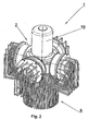
- Fig. 2 eine perspektivische Ansicht des Stirlingmotors gemäß Fig. 1;
- Fig. 3 eine Draufsicht auf das Planetengetriebe samt Arbeitskolben;
- Fig. 4 einen Schnitt gemäß der Linie IV-IV in Fig. 3;
- Fig. 5 eine teilweise aufgebrochene perspektivische Ansicht des Planetengetriebes des Stirlingmotors samt Arbeitskolben; und
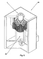
- Fig. 6 schematisch eine perspektivische teilweise aufgebrochene Ansicht einer Biomassefeuerungsanlage mit einem integrierten Stirlingmotor.
- In den Figuren 1 und 2 ist ein Stirlingmotor 1 gezeigt, bei dem vier Arbeitszylinder 2 mit darin verschiebbar gelagerten Arbeitskolben 3 jeweils um 90° zueinander verdreht angeordnet sind, so dass sich bei einer Draufsicht auf den Stirlingmotor 1 eine sog. X-Anordnung der Arbeitszylinder bzw. Kolben ergibt.
- Die vier Kolben 3, die an zwei doppelten Kolbenstangen 3' befestigt sind, sind über ein Planetengetriebe 4 (vgl. insbesondere Fig. 4) miteinander gekoppelt, wodurch die Linearbewegung der Arbeitskolben 3 in eine Rotationsbewegung einer Abtriebswelle 5 umgesetzt wird, und zugleich auch die für den Stirlingmotor erforderliche phasenverschobene Bewegung zwischen den Kolbenpaaren sowie eine exakte Geradeführung der Arbeitskolben 3 in den Arbeitszylindern 2 erzielt wird.
- An die Zylinder 2 schließen jeweils außenliegende Erhitzerrohre 6 an, in welchen das darin befindliche Arbeitsgas erhitzt wird und in einen heißen Arbeitsraum 2' des Arbeitszylinders 2 strömt. Die Erhitzerrohre 6 münden jeweils in einem Regenerator 7, über den bei jedem Kolbenhub im Arbeitszylinder 2 durch Überströmen des Gases vom heißen Bereich 2' in den kalten Bereich 2" (und umgekehrt) ein Teil der Wärme ausgetauscht wird.
- Der Regenerator 7 ist - ähnlich einem Hohlzylinder - jeweils etwa in der Mitte des Arbeitszylinders 2 aufgesteckt. Jeder Regenerator 7 ist mit den Erhitzerrohren 6 und einem Wärmetauscher bzw. Kühler 8 verbunden und mit Metallsieben gefüllt. Somit wird - je nach Richtung, in der das Arbeitsgas strömt - das aus den Erhitzerrohren 6 strömende Arbeitsgas gekühlt bzw. aus dem Kühler 8 strömende Arbeitsgas erwärmt. Die Kühler 8 sind jeweils ringförmig um den inneren, getriebenahen Teil eines Arbeitszylinders 2 zwischen dem Regenerator 7 und einem Getriebegehäuse 9 angeordnet und kühlt diesen Bereich des Arbeitszylinders 2. Die Kühler 8 bestehen arbeitsgasseitig aus einem Rohr, das den Regenerator 7 mit der Unterseite des Kolbens 3 des nächsten Zylinders 2 verbindet. Damit wird - je nach Richtung, in der das Arbeitsgas strömt - das aus dem Regenerator 7 strömende Arbeitsgas gekühlt bzw. das aus dem kalten Bereich 2" des nächsten Zylinders 2 strömende Arbeitsgas erwärmt.
- Als Kühlmedium kann Wasser vorgesehen sein, das mit dem Heizwasserkreislauf z.B. einer Biomassefeuerungsanlage 20 (vgl. Fig. 6) verbunden ist und so die Nutzung der Abwärme des Motors zu Heizzwecken ermöglicht.
- Das Getriebegehäuse 9 ist wassergekühlt, druckdicht gekapselt, und enthält neben dem Getriebe 4 Schmieröl, eine Schmierölpumpe und eventuell eine Vorrichtung, um den Gasdruck zu regulieren.
- An das Getriebegehäuse sind die vier Arbeitszylinder 2 mit Kühler 8, Regenerator 7 und Erhitzerrohre 6 sowie ein Adapter für die Einbindung in eine Biomassefeuerungsanlage 20 (vgl. Fig. 7) und ein Stromgenerator 10 angeflanscht.
- Wenn der angeflanschte Generator 10 ebenfalls gas- und druckdicht ausgeführt ist, dann stellen die Kolbenstangen 3' die einzige, dynamisch abzudichtende Verbindung dar, welche aber nicht den vollen Arbeitsdruck abdichten müssen, sondern nur die Druckdifferenz zum Getriebegehäuse 9, welche relativ niedrig ist.
- Der Druck im Getriebegehäuse 9 und im Generator 10 ist annähernd gleich hoch wie der mittlere Druck der vier Arbeitsgasvolumina, wobei dieser Druck vorteilhafterweise nur sehr wenig schwankt.
- Der Stromgenerator 10 wird vorteilhafterweise netzgekoppelt betrieben, wobei die Leistungsabgabe an das Stromnetz entsprechend der Wärmezufuhr der Feuerungsanlage an das Arbeitsgas erfolgt.
- Um einen auch nach längerem Stillstand selbstanlaufenden Stirlingmotor zu erzielen, dessen Leistung lediglich durch die Intensität der Wärmezufuhr und den Gasdruck bestimmt wird, wobei der Motor ohne freie Massenkräfte und -momente betrieben werden kann, sind die Arbeitskolben 3 über das in den Figuren 3 bis 5 im Detail dargestellte Planetengetriebe 4 miteinander gekoppelt.
- Das Planetengetriebe 4 weist eine Kurbel 11 auf, an welcher die beiden Kolbenstangen 3' drehbar gelagert sind. Die Kurbel 11 weist in ihren beiden Endbereichen jeweils eine Außenverzahnung 12, 12' auf, wobei anstelle der unteren Verzahnung auch lediglich eine Lagerung, beispielsweise mittels Kugellagern, zur Kraftaufnahme und zur Verhinderung einer Verkantung vorgesehen sein kann.
- Die Kurbel 11 greift mit ihren endseitigen Verzahnungen 12, 12' in einem oberen und einem unteren Hohlrad 13, 13' kämmend ein, so dass die Kurbel 11 in den Hohlrädern 13, 13' in der Art eines Planetenrades umläuft. Hiebei nimmt die Kurbel 11 zwei Ausgleichsmassen 14, 14' mit, so dass der gemeinsame Schwerpunkt aller bewegten Teile sich auf der Drehachse der Abtriebswelle 5 befindet. Da sich zudem die Schwerpunkte der beiden Doppelkolben 3 in einer Ebene senkrecht zur Drehachse befinden, wird ein vollständiger Ausgleich der freien Massenkräfte und -momente erzielt.
- Die Kurbel 11 ist in den Ausgleichsmassen 14, 14' mittels Kugellagern 15, 15' gelagert, wobei die Ausgleichsmassen 14, 14' radial außen wiederum für eine statisch einwandfreie Lagerung an dem drehfest angeordneten Getriebegehäuse 9 gelagert sind.
- Das untere Hohlrad 13' ist zudem von einem Ansaugrohr 16 umgeben, über welches Öl in das Innere des Getriebegehäuses 9 mittels der Verzahnung zwischen der Kurbel 11 und dem Hohlrad 13' gefördert wird. Das Öl wird somit im Inneren des Getriebegehäuses 9 verstäubt, so dass das Vorsehen einer gesonderten Ölpumpe nicht erforderlich ist.
- In Fig. 5 ist zudem noch ersichtlich, dass die Ausgleichsmassen 14, 14' zusätzlich zu ihrer innenseitigen Lagerung mittels Lagern 15, 15' auch radial außen im Getriebegehäuse 9 mittels Lagern 16, 16' gelagert sind. Als Lager 15, 15' bzw. 16, 16' können insbesondere Kugel- oder Nadellager vorgesehen sein, wobei für eine statisch einwandfreie Lagerung entweder die Lager 15, 15' als Loslager und die Lager 16, 16' als Festlager (oder umgekehrt) angeordnet sind.
- In Fig. 6 ist der Stirlingmotor 1 in einer Brennkammer 19 einer Biomassefeuerungsanlage 20 angeordnet, so dass die Flammen aus der Brennkammer 19 ihre Wärme einerseits durch Flammstrahlung und andererseits durch Konvektion beim Durchströmen an die Erhitzerrohre 6 des Stirlingmotors 1 abgeben. Durch diese Anordnung wird sowohl eine Ausnutzung der Strahlungswärme als auch ein widerstandsarmer Durchtritt des heißen Rauchgases ermöglicht, das nach der Wärmeübertragung an die Erhitzerrohre den bei konventionellen Biomassefeuerungsanlagen üblichen Weg zur Erzeugung von Wärme fortsetzt.
Claims (10)
- Stirlingmotor (1) mit vier jeweils um 90° zueinander verdreht angeordneten Arbeitskolben (3), mit einem Planetengetriebe (4) zur Umsetzung der Linearbewegung der Arbeitskolben (3) in eine Rotationsbewegung einer gemeinsamen Abtriebswelle (5), wobei die Schwerpunkte der vier Arbeitskolben (3) in einer gemeinsamen Ebene senkrecht zur Drehachse der Abtriebswelle (5) angeordnet sind, und die Arbeitskolben (3) zur Geradeführung an einer als Planetenrad ausgebildeten außenverzahnten Kurbel (11) drehbar gelagert sind, die in zumindest einem innenverzahnten Hohlrad (13, 13') umläuft, wobei zum vollständigen Ausgleich freier Massenkräfte und -momente lediglich der gemeinsamen Abtriebswelle (5) zumindest zwei Ausgleichsmassen (14, 14') derart zugeordnet sind, dass die Arbeitskolben (3) und die mit den Arbeitskolben (3) mitbewegten Getriebeteile einen gemeinsamen, in der Achse der Abtriebswelle (5) liegenden Schwerpunkt aufweisen.
- Stirlingmotor nach Anspruch 1, dadurch gekennzeichnet, dass doppelt wirkende Arbeitskolben (3) vorgesehen sind.
- Stirlingmotor nach Anspruch 1 oder 2, dadurch gekennzeichnet, dass eine Ausgleichsmasse (14) mit der Abtriebswelle (5) einstückig ausgebildet ist.
- Stirlingmotor nach Anspruch 2, dadurch gekennzeichnet, dass durch die Verzahnung zwischen der außenverzahnten Kurbel (11) und dem innenverzahnten Hohlrad (13') Ö1 gefördert wird.
- Stirlingmotor nach einem der Ansprüche 1 bis 4, dadurch gekennzeichnet, dass die Kurbel (11) in beiden Endabschnitten eine Außenverzahnung (12, 12') zum Eingriff in zwei endseitig angeordneten innenverzahnten Hohlrädern (13, 13') aufweist.
- Stirlingmotor nach Anspruch 5, dadurch gekennzeichnet, dass die Kurbel (11) zwischen den beiden Hohlrädern (13, 13') in den Ausgleichsmassen (14, 14'), vorzugsweise mittels Nadel- oder Rolllagern (16, 16'), exzentrisch zu der Abtriebswelle (5) gelagert ist.
- Stirlingmotor nach einem der Ansprüche 3 bis 6, dadurch gekennzeichnet, dass die Ausgleichsmassen (14, 14') innenseitig zur Kurbel (11) und außenseitig zu einem drehfest angeordneten Gehäuse (9) gelagert sind, wobei ein Lager (15, 15'; 16, 16') ein Loslager und ein Lager (15, 15'; 16, 16') ein Festlager ist.
- Biomassefeuerungsanlage (20) mit einer Brennkammer (19), dadurch gekennzeichnet, dass in der Brennkammer (19) ein Stirlingmotor (1) nach einem der Ansprüche 1 bis 7 vorgesehen ist.
- Biomassefeuerungsanlage nach Anspruch 8, dadurch gekennzeichnet, dass an die Arbeitszylinder (2) des Stirlingmotors (1) zur Erhitzung des Arbeitsgases vom Arbeitsgas durchströmte Erhitzerrohre (6) anschließen.
- Biomassefeuerungsanlage nach Anspruch 8 oder 9, dadurch gekennzeichnet, dass der Stirlingmotor (1) modular in der Brennkammer (19) der Biomassefeuerungsanlage (20) integrierbar ist.
Priority Applications (2)
| Application Number | Priority Date | Filing Date | Title |
|---|---|---|---|
| SI200430089T SI1455117T1 (sl) | 2003-03-06 | 2004-03-05 | Stirlingov motor in kurilna naprava za biomaso |
| AT04450049T ATE333609T1 (de) | 2003-03-06 | 2004-03-05 | Stirlingmotor sowie biomassefeuerungsanlage |
Applications Claiming Priority (2)
| Application Number | Priority Date | Filing Date | Title |
|---|---|---|---|
| AT3352003A AT412806B (de) | 2003-03-06 | 2003-03-06 | Stirlingmotor sowie biomassefeuerungsanlage |
| AT3352003 | 2003-03-06 |
Publications (2)
| Publication Number | Publication Date |
|---|---|
| EP1455117A1 EP1455117A1 (de) | 2004-09-08 |
| EP1455117B1 true EP1455117B1 (de) | 2006-07-19 |
Family
ID=32777528
Family Applications (1)
| Application Number | Title | Priority Date | Filing Date |
|---|---|---|---|
| EP20040450049 Expired - Lifetime EP1455117B1 (de) | 2003-03-06 | 2004-03-05 | Stirlingmotor sowie Biomassefeuerungsanlage |
Country Status (4)
| Country | Link |
|---|---|
| EP (1) | EP1455117B1 (de) |
| AT (1) | AT412806B (de) |
| DE (1) | DE502004000966D1 (de) |
| ES (1) | ES2268616T3 (de) |
Cited By (1)
| Publication number | Priority date | Publication date | Assignee | Title |
|---|---|---|---|---|
| CN101881720A (zh) * | 2010-06-12 | 2010-11-10 | 北京农业智能装备技术研究中心 | 基于力矩的生物量活体检测装置及方法 |
Families Citing this family (3)
| Publication number | Priority date | Publication date | Assignee | Title |
|---|---|---|---|---|
| DE102004047054A1 (de) * | 2004-09-28 | 2006-11-30 | Hugo Post | Modifikation Flachplatten-Stirlingmotor und Prozessanbindung |
| DE102007048639A1 (de) | 2007-10-10 | 2009-04-16 | Roland Nagler | Wärmekraftmaschine |
| DE102009023024A1 (de) * | 2009-05-28 | 2010-12-09 | Schliebe, Günther | Stirlingmotoranordnung |
Family Cites Families (6)
| Publication number | Priority date | Publication date | Assignee | Title |
|---|---|---|---|---|
| DE2305811C2 (de) * | 1973-02-07 | 1982-03-11 | Ivan Crnuce Koderman | Zahnrad-Kurbelgetriebe |
| US4241580A (en) * | 1978-11-30 | 1980-12-30 | Ford Motor Company | Stirling engine |
| DE3023363A1 (de) * | 1980-06-23 | 1982-01-07 | Walter 7000 Stuttgart Schulz | Kreuzhubsternmotor mit planetengetriebe |
| DE3114459A1 (de) * | 1981-04-09 | 1982-10-28 | Walter 8240 Berchtesgaden Schmied | Kurbeltrieb fuer eine hubkolbenmaschine |
| DE4336982A1 (de) * | 1993-10-29 | 1995-05-04 | Erno Raumfahrttechnik Gmbh | Energieerzeugungseinrichtung |
| NL1009211C2 (nl) * | 1998-05-19 | 1999-11-22 | L H De Gooijer Holding B V | Kruk-drijfstangmechanisme. |
-
2003
- 2003-03-06 AT AT3352003A patent/AT412806B/de not_active IP Right Cessation
-
2004
- 2004-03-05 ES ES04450049T patent/ES2268616T3/es not_active Expired - Lifetime
- 2004-03-05 EP EP20040450049 patent/EP1455117B1/de not_active Expired - Lifetime
- 2004-03-05 DE DE200450000966 patent/DE502004000966D1/de not_active Expired - Lifetime
Cited By (1)
| Publication number | Priority date | Publication date | Assignee | Title |
|---|---|---|---|---|
| CN101881720A (zh) * | 2010-06-12 | 2010-11-10 | 北京农业智能装备技术研究中心 | 基于力矩的生物量活体检测装置及方法 |
Also Published As
| Publication number | Publication date |
|---|---|
| DE502004000966D1 (de) | 2006-08-31 |
| ES2268616T3 (es) | 2007-03-16 |
| EP1455117A1 (de) | 2004-09-08 |
| AT412806B (de) | 2005-07-25 |
| ATA3352003A (de) | 2004-12-15 |
Similar Documents
| Publication | Publication Date | Title |
|---|---|---|
| DE69818473T2 (de) | Stirling zyklus maschine | |
| DE3224482C2 (de) | Kolbenmaschine | |
| DE10145478B4 (de) | Hubkolbenmaschine mit umlaufendem Zylinder | |
| EP0153675B1 (de) | Brennkraftmaschine | |
| EP0725894B1 (de) | Energieerzeugungseinrichtung | |
| DE4018943A1 (de) | Kolbenmaschine | |
| DE19814742C1 (de) | Kreiskolben-Wärmemotor-Vorrichtung | |
| EP0607154A1 (de) | Energiewandler nach dem prinzip des heissluftmotors. | |
| EP0369991B1 (de) | Dreh-Hubkolben-Maschine | |
| EP1455117B1 (de) | Stirlingmotor sowie Biomassefeuerungsanlage | |
| DE3723950A1 (de) | Regenerative waermemaschine mit einem hypozykloidischen exzenter-kurbelgetriebe | |
| DE60214685T2 (de) | Expansionsmaschine | |
| EP1682749B1 (de) | Kreiskolben-wärmemotor-vorrichtung | |
| DE69627167T2 (de) | Rotierende brennkraftmaschine | |
| DE102020004112A1 (de) | Verbundexzentergetriebe mit gekoppelten umlaufenden Wellen zur Umwandlung hin- und hergehender Bewegungen in eine kontinuierliche Drehbewegung und umgekehrt | |
| DE2518554A1 (de) | Antriebsmaschine mit innerer kontinuierlicher verbrennung | |
| DE2753125A1 (de) | Heissgasmaschine | |
| WO2002084078A1 (de) | Kreiskolben-wärmemotor-vorrichtung | |
| DE3523785A1 (de) | Vorrichtung zur steuerung bzw. zum an- oder abtrieb von linear- und freikolbenmaschinen | |
| DE4239074C2 (de) | Rotationsschwingkolbenmotor | |
| DE599340C (de) | Durch eine Kurvenbahn um ihre Zylinderlaengsachse rotierende Verbrennungskraftmaschine | |
| DE3882702T2 (de) | Mechanismus zur übertragung einer bewegung. | |
| DE102014011241B3 (de) | 2-Zyklen-Stirlingmaschine mit zwei doppelt wirkenden Kolben | |
| EP3092370B1 (de) | Gleichraumverbrennungsmotor | |
| DE202009001639U1 (de) | Drehkolbenmaschinenanordnung |
Legal Events
| Date | Code | Title | Description |
|---|---|---|---|
| PUAI | Public reference made under article 153(3) epc to a published international application that has entered the european phase |
Free format text: ORIGINAL CODE: 0009012 |
|
| AK | Designated contracting states |
Kind code of ref document: A1 Designated state(s): AT BE BG CH CY CZ DE DK EE ES FI FR GB GR HU IE IT LI LU MC NL PL PT RO SE SI SK TR |
|
| AX | Request for extension of the european patent |
Extension state: AL HR LT LV MK |
|
| 17P | Request for examination filed |
Effective date: 20050223 |
|
| 17Q | First examination report despatched |
Effective date: 20050412 |
|
| AKX | Designation fees paid |
Designated state(s): AT BE BG CH CY CZ DE DK EE ES FI FR GB GR HU IE IT LI LU MC NL PL PT RO SE SI SK TR |
|
| GRAP | Despatch of communication of intention to grant a patent |
Free format text: ORIGINAL CODE: EPIDOSNIGR1 |
|
| GRAC | Information related to communication of intention to grant a patent modified |
Free format text: ORIGINAL CODE: EPIDOSCIGR1 |
|
| GRAS | Grant fee paid |
Free format text: ORIGINAL CODE: EPIDOSNIGR3 |
|
| GRAA | (expected) grant |
Free format text: ORIGINAL CODE: 0009210 |
|
| AK | Designated contracting states |
Kind code of ref document: B1 Designated state(s): AT BE BG CH CY CZ DE DK EE ES FI FR GB GR HU IE IT LI LU MC NL PL PT RO SE SI SK TR |
|
| PG25 | Lapsed in a contracting state [announced via postgrant information from national office to epo] |
Ref country code: IT Free format text: LAPSE BECAUSE OF FAILURE TO SUBMIT A TRANSLATION OF THE DESCRIPTION OR TO PAY THE FEE WITHIN THE PRESCRIBED TIME-LIMIT;WARNING: LAPSES OF ITALIAN PATENTS WITH EFFECTIVE DATE BEFORE 2007 MAY HAVE OCCURRED AT ANY TIME BEFORE 2007. THE CORRECT EFFECTIVE DATE MAY BE DIFFERENT FROM THE ONE RECORDED. Effective date: 20060719 Ref country code: FI Free format text: LAPSE BECAUSE OF FAILURE TO SUBMIT A TRANSLATION OF THE DESCRIPTION OR TO PAY THE FEE WITHIN THE PRESCRIBED TIME-LIMIT Effective date: 20060719 Ref country code: NL Free format text: LAPSE BECAUSE OF FAILURE TO SUBMIT A TRANSLATION OF THE DESCRIPTION OR TO PAY THE FEE WITHIN THE PRESCRIBED TIME-LIMIT Effective date: 20060719 Ref country code: RO Free format text: LAPSE BECAUSE OF FAILURE TO SUBMIT A TRANSLATION OF THE DESCRIPTION OR TO PAY THE FEE WITHIN THE PRESCRIBED TIME-LIMIT Effective date: 20060719 Ref country code: CZ Free format text: LAPSE BECAUSE OF FAILURE TO SUBMIT A TRANSLATION OF THE DESCRIPTION OR TO PAY THE FEE WITHIN THE PRESCRIBED TIME-LIMIT Effective date: 20060719 Ref country code: SK Free format text: LAPSE BECAUSE OF FAILURE TO SUBMIT A TRANSLATION OF THE DESCRIPTION OR TO PAY THE FEE WITHIN THE PRESCRIBED TIME-LIMIT Effective date: 20060719 Ref country code: PL Free format text: LAPSE BECAUSE OF FAILURE TO SUBMIT A TRANSLATION OF THE DESCRIPTION OR TO PAY THE FEE WITHIN THE PRESCRIBED TIME-LIMIT Effective date: 20060719 |
|
| REG | Reference to a national code |
Ref country code: GB Ref legal event code: FG4D Free format text: NOT ENGLISH |
|
| REG | Reference to a national code |
Ref country code: CH Ref legal event code: EP |
|
| REG | Reference to a national code |
Ref country code: IE Ref legal event code: FG4D Free format text: LANGUAGE OF EP DOCUMENT: GERMAN |
|
| REF | Corresponds to: |
Ref document number: 502004000966 Country of ref document: DE Date of ref document: 20060831 Kind code of ref document: P |
|
| REG | Reference to a national code |
Ref country code: CH Ref legal event code: NV Representative=s name: ROTTMANN, ZIMMERMANN + PARTNER AG |
|
| PG25 | Lapsed in a contracting state [announced via postgrant information from national office to epo] |
Ref country code: DK Free format text: LAPSE BECAUSE OF FAILURE TO SUBMIT A TRANSLATION OF THE DESCRIPTION OR TO PAY THE FEE WITHIN THE PRESCRIBED TIME-LIMIT Effective date: 20061019 Ref country code: SE Free format text: LAPSE BECAUSE OF FAILURE TO SUBMIT A TRANSLATION OF THE DESCRIPTION OR TO PAY THE FEE WITHIN THE PRESCRIBED TIME-LIMIT Effective date: 20061019 Ref country code: BG Free format text: LAPSE BECAUSE OF FAILURE TO SUBMIT A TRANSLATION OF THE DESCRIPTION OR TO PAY THE FEE WITHIN THE PRESCRIBED TIME-LIMIT Effective date: 20061019 |
|
| GBT | Gb: translation of ep patent filed (gb section 77(6)(a)/1977) |
Effective date: 20061012 |
|
| PG25 | Lapsed in a contracting state [announced via postgrant information from national office to epo] |
Ref country code: PT Free format text: LAPSE BECAUSE OF FAILURE TO SUBMIT A TRANSLATION OF THE DESCRIPTION OR TO PAY THE FEE WITHIN THE PRESCRIBED TIME-LIMIT Effective date: 20061219 |
|
| NLV1 | Nl: lapsed or annulled due to failure to fulfill the requirements of art. 29p and 29m of the patents act | ||
| ET | Fr: translation filed | ||
| REG | Reference to a national code |
Ref country code: ES Ref legal event code: FG2A Ref document number: 2268616 Country of ref document: ES Kind code of ref document: T3 |
|
| PLBE | No opposition filed within time limit |
Free format text: ORIGINAL CODE: 0009261 |
|
| STAA | Information on the status of an ep patent application or granted ep patent |
Free format text: STATUS: NO OPPOSITION FILED WITHIN TIME LIMIT |
|
| 26N | No opposition filed |
Effective date: 20070420 |
|
| PG25 | Lapsed in a contracting state [announced via postgrant information from national office to epo] |
Ref country code: MC Free format text: LAPSE BECAUSE OF NON-PAYMENT OF DUE FEES Effective date: 20070331 |
|
| PG25 | Lapsed in a contracting state [announced via postgrant information from national office to epo] |
Ref country code: GR Free format text: LAPSE BECAUSE OF FAILURE TO SUBMIT A TRANSLATION OF THE DESCRIPTION OR TO PAY THE FEE WITHIN THE PRESCRIBED TIME-LIMIT Effective date: 20061020 |
|
| PG25 | Lapsed in a contracting state [announced via postgrant information from national office to epo] |
Ref country code: EE Free format text: LAPSE BECAUSE OF FAILURE TO SUBMIT A TRANSLATION OF THE DESCRIPTION OR TO PAY THE FEE WITHIN THE PRESCRIBED TIME-LIMIT Effective date: 20060719 |
|
| PGFP | Annual fee paid to national office [announced via postgrant information from national office to epo] |
Ref country code: IE Payment date: 20090313 Year of fee payment: 6 |
|
| PGFP | Annual fee paid to national office [announced via postgrant information from national office to epo] |
Ref country code: SI Payment date: 20090305 Year of fee payment: 6 |
|
| PGFP | Annual fee paid to national office [announced via postgrant information from national office to epo] |
Ref country code: BE Payment date: 20090313 Year of fee payment: 6 |
|
| PG25 | Lapsed in a contracting state [announced via postgrant information from national office to epo] |
Ref country code: CY Free format text: LAPSE BECAUSE OF FAILURE TO SUBMIT A TRANSLATION OF THE DESCRIPTION OR TO PAY THE FEE WITHIN THE PRESCRIBED TIME-LIMIT Effective date: 20060719 Ref country code: LU Free format text: LAPSE BECAUSE OF NON-PAYMENT OF DUE FEES Effective date: 20070305 |
|
| PG25 | Lapsed in a contracting state [announced via postgrant information from national office to epo] |
Ref country code: TR Free format text: LAPSE BECAUSE OF FAILURE TO SUBMIT A TRANSLATION OF THE DESCRIPTION OR TO PAY THE FEE WITHIN THE PRESCRIBED TIME-LIMIT Effective date: 20060719 Ref country code: HU Free format text: LAPSE BECAUSE OF FAILURE TO SUBMIT A TRANSLATION OF THE DESCRIPTION OR TO PAY THE FEE WITHIN THE PRESCRIBED TIME-LIMIT Effective date: 20070120 |
|
| PGFP | Annual fee paid to national office [announced via postgrant information from national office to epo] |
Ref country code: CH Payment date: 20100331 Year of fee payment: 7 |
|
| PGFP | Annual fee paid to national office [announced via postgrant information from national office to epo] |
Ref country code: IT Payment date: 20100324 Year of fee payment: 7 |
|
| PGFP | Annual fee paid to national office [announced via postgrant information from national office to epo] |
Ref country code: GB Payment date: 20100325 Year of fee payment: 7 |
|
| BERE | Be: lapsed |
Owner name: *PTAK GEORG Effective date: 20100331 Owner name: *STANZEL KARL WOLFGANG Effective date: 20100331 |
|
| REG | Reference to a national code |
Ref country code: SI Ref legal event code: KO00 Effective date: 20101013 |
|
| PG25 | Lapsed in a contracting state [announced via postgrant information from national office to epo] |
Ref country code: IE Free format text: LAPSE BECAUSE OF NON-PAYMENT OF DUE FEES Effective date: 20100305 |
|
| PG25 | Lapsed in a contracting state [announced via postgrant information from national office to epo] |
Ref country code: BE Free format text: LAPSE BECAUSE OF NON-PAYMENT OF DUE FEES Effective date: 20100331 Ref country code: SI Free format text: LAPSE BECAUSE OF NON-PAYMENT OF DUE FEES Effective date: 20100306 |
|
| PGFP | Annual fee paid to national office [announced via postgrant information from national office to epo] |
Ref country code: FR Payment date: 20110217 Year of fee payment: 8 |
|
| PGFP | Annual fee paid to national office [announced via postgrant information from national office to epo] |
Ref country code: ES Payment date: 20110210 Year of fee payment: 8 |
|
| REG | Reference to a national code |
Ref country code: CH Ref legal event code: PFA Owner name: PTAK, GEORG Free format text: PTAK, GEORG#DORFSTRASSE 103#8750 OBERWEG/JUDENBURG (AT) $ STANZEL, KARL WOLFGANG#NIKOLAUS-SCHOENBACHER-STRASSE 7#8010 GRAZ (AT) -TRANSFER TO- PTAK, GEORG#DORFSTRASSE 103#8750 OBERWEG/JUDENBURG (AT) $ STANZEL, KARL WOLFGANG#NIKOLAUS-SCHOENBACHER-STRASSE 7#8010 GRAZ (AT) |
|
| REG | Reference to a national code |
Ref country code: CH Ref legal event code: PL |
|
| GBPC | Gb: european patent ceased through non-payment of renewal fee |
Effective date: 20110305 |
|
| PG25 | Lapsed in a contracting state [announced via postgrant information from national office to epo] |
Ref country code: LI Free format text: LAPSE BECAUSE OF NON-PAYMENT OF DUE FEES Effective date: 20110331 Ref country code: CH Free format text: LAPSE BECAUSE OF NON-PAYMENT OF DUE FEES Effective date: 20110331 |
|
| PG25 | Lapsed in a contracting state [announced via postgrant information from national office to epo] |
Ref country code: GB Free format text: LAPSE BECAUSE OF NON-PAYMENT OF DUE FEES Effective date: 20110305 |
|
| PGFP | Annual fee paid to national office [announced via postgrant information from national office to epo] |
Ref country code: DE Payment date: 20120327 Year of fee payment: 9 |
|
| REG | Reference to a national code |
Ref country code: FR Ref legal event code: ST Effective date: 20121130 |
|
| PG25 | Lapsed in a contracting state [announced via postgrant information from national office to epo] |
Ref country code: FR Free format text: LAPSE BECAUSE OF NON-PAYMENT OF DUE FEES Effective date: 20120402 |
|
| PGFP | Annual fee paid to national office [announced via postgrant information from national office to epo] |
Ref country code: AT Payment date: 20120327 Year of fee payment: 9 |
|
| REG | Reference to a national code |
Ref country code: ES Ref legal event code: FD2A Effective date: 20130711 |
|
| PG25 | Lapsed in a contracting state [announced via postgrant information from national office to epo] |
Ref country code: ES Free format text: LAPSE BECAUSE OF NON-PAYMENT OF DUE FEES Effective date: 20120306 |
|
| REG | Reference to a national code |
Ref country code: AT Ref legal event code: MM01 Ref document number: 333609 Country of ref document: AT Kind code of ref document: T Effective date: 20130305 |
|
| REG | Reference to a national code |
Ref country code: DE Ref legal event code: R119 Ref document number: 502004000966 Country of ref document: DE Effective date: 20131001 |
|
| PG25 | Lapsed in a contracting state [announced via postgrant information from national office to epo] |
Ref country code: DE Free format text: LAPSE BECAUSE OF NON-PAYMENT OF DUE FEES Effective date: 20131001 Ref country code: AT Free format text: LAPSE BECAUSE OF NON-PAYMENT OF DUE FEES Effective date: 20130305 |
|
| PG25 | Lapsed in a contracting state [announced via postgrant information from national office to epo] |
Ref country code: IT Free format text: LAPSE BECAUSE OF NON-PAYMENT OF DUE FEES Effective date: 20110305 |