EP1455139A2 - Sichtfenster-anordnung für einen herd - Google Patents
Sichtfenster-anordnung für einen herd Download PDFInfo
- Publication number
- EP1455139A2 EP1455139A2 EP20040450052 EP04450052A EP1455139A2 EP 1455139 A2 EP1455139 A2 EP 1455139A2 EP 20040450052 EP20040450052 EP 20040450052 EP 04450052 A EP04450052 A EP 04450052A EP 1455139 A2 EP1455139 A2 EP 1455139A2
- Authority
- EP
- European Patent Office
- Prior art keywords
- viewing window
- air
- window arrangement
- glass plates
- arrangement according
- Prior art date
- Legal status (The legal status is an assumption and is not a legal conclusion. Google has not performed a legal analysis and makes no representation as to the accuracy of the status listed.)
- Withdrawn
Links
- 239000011521 glass Substances 0.000 claims abstract description 61
- 238000002485 combustion reaction Methods 0.000 claims abstract description 44
- 239000004449 solid propellant Substances 0.000 claims abstract description 8
- 238000000576 coating method Methods 0.000 claims description 9
- 239000000446 fuel Substances 0.000 claims description 4
- 230000001154 acute effect Effects 0.000 claims description 2
- 238000010304 firing Methods 0.000 claims description 2
- 239000005871 repellent Substances 0.000 claims description 2
- 238000001816 cooling Methods 0.000 description 14
- 230000005855 radiation Effects 0.000 description 5
- 239000004071 soot Substances 0.000 description 5
- 230000015572 biosynthetic process Effects 0.000 description 4
- 238000010438 heat treatment Methods 0.000 description 4
- 230000000694 effects Effects 0.000 description 3
- 239000011248 coating agent Substances 0.000 description 2
- 238000010411 cooking Methods 0.000 description 2
- 230000035515 penetration Effects 0.000 description 2
- 230000001105 regulatory effect Effects 0.000 description 2
- 238000010792 warming Methods 0.000 description 2
- 230000000052 comparative effect Effects 0.000 description 1
- 230000002349 favourable effect Effects 0.000 description 1
- 230000000977 initiatory effect Effects 0.000 description 1
- 239000011810 insulating material Substances 0.000 description 1
- 238000009413 insulation Methods 0.000 description 1
- 239000000463 material Substances 0.000 description 1
- 238000001556 precipitation Methods 0.000 description 1
- 230000000630 rising effect Effects 0.000 description 1
Images
Classifications
-
- F—MECHANICAL ENGINEERING; LIGHTING; HEATING; WEAPONS; BLASTING
- F24—HEATING; RANGES; VENTILATING
- F24B—DOMESTIC STOVES OR RANGES FOR SOLID FUELS; IMPLEMENTS FOR USE IN CONNECTION WITH STOVES OR RANGES
- F24B13/00—Details solely applicable to stoves or ranges burning solid fuels
- F24B13/004—Doors specially adapted for stoves or ranges
Definitions
- the invention relates to a viewing window arrangement for a a stove with a combustion chamber, in particular a solid fuel stove, with at least two spaced apart heat-resistant glass plates, whereby in a surrounding the glass plates Mounting frame air passage openings provided through which air is passed between the glass plates.
- Such a viewing window arrangement is from the US 4 163 444 A, in which four glass plates are provided are arranged so that they are spaced from one another such that three air ducts are formed.
- Door air inlet openings are provided, being through the innermost Air duct ducted air through air outlet openings for heating an upper cooking surface between an upper end plate of the combustion chamber and the upper cooking surface is directed.
- From US 5 441 036 A is a viewing window arrangement for known a stove in which several spaced apart Glass plates are provided, between which cooling air is passed becomes.
- the air passed between the glass plates becomes in the upper end section of the stove door via air openings derived into the environment.
- GB 1 552 850 A is also a viewing window arrangement known for a stove, in which three glass plates in Are spaced from each other and cooling air through a duct is passed between the glass plates.
- GB 1 531 199 A also has a viewing window arrangement for a stove with three spaced apart Glass plates with an air passage duct for cooling the Outer pane described.
- DE 201 09 880 U is still a viewing window known for oven doors, with a glass pane on a coating on the inside facing the oven made of a special insulating material.
- the aim of the present invention is now a viewing window arrangement to create for a stove of the type mentioned at the beginning, through which an unrestricted view of the fire in the Combustion chamber is possible, so that the stove has an atmosphere in it Kind of a fireplace conveyed, but at the same time on that of Outside of the viewing window arrangement facing away from the combustion chamber - opposite to traditional fireplaces - a comparative low temperature, so that a stove user longer Time can linger near the hearth without one for being exposed to uncomfortable heat.
- the coatings preferably on mutually facing inner sides of the Glass plates are provided.
- reflect Coatings radiation in the infrared range.
- the between air passed through the two glass plates for cooling purposes be so that depending on the out of the combustion chamber radiated amount of heat the air passed is regulated.
- Tests have shown that there is a particularly good shielding effect through the air introduced through the nozzle if the nozzle is inclined, preferably at an acute angle of 45 ° - 70 °, especially from essentially 60 °, to the horizontal is directed inwards into the combustion chamber.
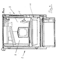
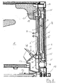
- Fig. 1 is a solid fuel stove 1 with a combustion chamber 2 can be seen, which has a door 3, which acts as a fastening frame 3 'for a viewing window arrangement shown in detail in FIG. 2 4 is provided.
- the viewing window arrangement 4 has an outer pane 5, from which two heat-resistant, coated disks 6, 6 'are arranged.
- the two coated disks 6, 6 ' are also in the Spaced from each other and point to each other facing insides each have a heat-resistant coating 7 on.
- the coatings consist of commercially available Materials that reflect radiation in the IR range.
- Airflow 8 is from a (primary) airflow of the solid fuel stove 1, in a base part 11 of the solid fuel range 1 is provided.
- a control valve 12 can Air flow 10 branched from the (primary) air flow for cooling the Viewing window arrangement 3 can be regulated.
- the branched air stream 10 then enters a lower one Strip 12 of the solid fuel stove, in which the Airflow 10 divides.
- a partial flow 10 'passes through air passage openings 13 in a stove frame adjoining the door 4 14 and via air passage openings 13 'in the back of the mounting frame 3 'inside the door 4.
- This Partial stream 10 'then bifurcates between the two coated glass panes 6, 6 'passed through air flow 8 and an outer between the outer pane 5 and the outer of the coated discs 6 passed air flow 10 ''.
- air passage openings 13, 13 ' are provided, via which the now heated air in the direction of arrow 9 into the combustion chamber 2 occurs. Some of the return air can also enter the combustion chamber directly via air passage openings 13 '', without previously passed over the inner coated disc 6 ' to become.
- the bar 12 is also provided with air passage openings 15, through which a partial flow 16 of the branched air flow 10 behind the inner coated disc 6, i.e. on the of the Outside facing away, introduced into the combustion chamber 2 becomes.
- the division of the branched air flow thus results 10 a substantially circular circulating Air flow through which a particularly useful cooling the viewing window arrangement 3 is achieved.
- the combustion chamber is usually located inside when burning of logs as fuel has a temperature of approx. 950 ° C before, so that the inner coated disc 6 'a disc temperature of approx. 560 ° C, the outer coated pane 6 ' a disc temperature of about 350 ° C, and that of the stove user facing outer pane 5 only one pane temperature of 230 ° C, allowing a user of the stove without exposed to uncomfortable heat radiation, longer Time can remain near the cooker 1.
- the nozzle 17 is about 60 ° to the horizontal inclined so that the air flow introduced via the nozzle 17 in Direction of arrow 18 is directed obliquely inwards, and thus the Heat emitted by the combustion chamber 2 from the viewing window arrangement 1 is pushed back.
Landscapes
- Engineering & Computer Science (AREA)
- Chemical & Material Sciences (AREA)
- Combustion & Propulsion (AREA)
- Mechanical Engineering (AREA)
- General Engineering & Computer Science (AREA)
- Wick-Type Burners And Burners With Porous Materials (AREA)
- Drying Of Solid Materials (AREA)
- Solid-Fuel Combustion (AREA)
Abstract
Description
Claims (13)
- Sichtfenster-Anordnung (3) für einen einen Brennraum (2) aufweisenden Herd (1), insbesondere einen Festbrennstoff-Herd, mit mindestens zwei voneinander beabstandeten hitzebeständigen Glasplatten (6, 6'), wobei in einem die Glasplatten (6, 6') umgebenden Befestigungsrahmen (3') Luftdurchtrittsöffnungen (13, 13', 13'') vorgesehen sind, wodurch Luft zwischen den Glasplatten (6, 6') durchgeleitet wird, dadurch gekennzeichnet, dass die Luftdurchtrittsöffnungen (13', 13'') derart angeordnet sind, dass die durchgeleitete Luft in den Brennraum (2) eingeleitet wird.
- Sichtfenster-Anordnung nach Anspruch 1, dadurch gekennzeichnet, dass die Glasplatten (6, 6') hitzabweisende Beschichtungen (7) aufweisen, wobei die Beschichtungen (7) an einander zugewandten Innenseiten der Glasplatten (6, 6') vorgesehen sind.
- Sichtfenster-Anordnung nach Anspruch 1 oder 2, dadurch gekennzeichnet, dass als Befestigungsrahmen (3') der Sichtfenster-Anordnung (3) eine Tür (4) vorgesehen ist.
- Sichtfenster-Anordnung nach einem der Ansprüche 1 bis 3, dadurch gekennzeichnet, dass die zwischen den Glasplatten (6, 6') durchgeleitete Luft (8) von einem Primärluftstrom zur Feuerung des Brennstoffs abgezweigt wird.
- Sichtfenster-Anordnung nach Anspruch 4, dadurch gekennzeichnet, dass ein Regelventil (12) zur Regelung des von dem Primärluftstrom abgezweigten Luftstroms (10) vorgesehen ist.
- Sichtfenster-Anordnung nach einem der Ansprüche 1 bis 5, dadurch gekennzeichnet, dass im Befestigungsrahmen (3') der Glasplatten (6, 6') an der von der Außenseite des Herds (1) abgewandten Rückseite Luftdurchtrittsöffnungen (13') vorgesehen sind.
- Sichtfenster-Anordnung nach einem der Ansprüche 1 bis 6, dadurch gekennzeichnet, dass in einem an den Befestigungsrahmen (3') angrenzenden Herdrahmen (14) Luftdurchtrittsöffnungen (15) vorgesehen sind, die mit dem Brennraum (2) direkt in Verbindung stehen.
- Sichtfenster-Anordnung nach einem der Ansprüche 1 bis 7, dadurch gekennzeichnet, dass die Luftdurchtrittsöffnungen (13, 13') unterhalb und oberhalb der Glasplatten (6, 6') angeordnet sind.
- Sichtfenster-Anordnung nach einem der Ansprüche 1 bis 8, dadurch gekennzeichnet, dass innerhalb der innersten hitzebeständigen Glasplatte (6') eine Düse (17) angeordnet ist, über die Luft in den Brennraum (2) geleitet wird,
- Sichtfenster-Anordnung nach Anspruch 9, dadurch gekennzeichnet, dass die Düse (17) schräg, vorzugsweise unter einem spitzen Winkel von 45° - 70°, insbesondere von im Wesentlichen 60°, zur Horizontalen nach innen in den Brennraum (2) gerichtet ist.
- Sichtfenster-Anordnung nach einem der Ansprüche 1 bis 10, dadurch gekennzeichnet, dass zumindest eine dritte von der äußersten der hitzebeständigen Glasplatten (6, 6') beabstandete Außenglasplatte (5) vorgesehen ist.
- Sichtfenster-Anordnung nach Anspruch 11, dadurch gekennzeichnet, dass zwischen der Außenglasplatte (5) und der benachbarten hitzebeständigen Glasplatte (6) ein Luftdurchtrittskanal für den abgezweigten Luftstrom (10) gebildet wird, wobei die durchströmende Luft (10'') in den Brennraum (2) abgeleitet wird.
- Sichtfenster-Anordnung nach Anspruch 12, dadurch gekennzeichnet, dass die der Außenglasplatte (5) benachbarte hitzebeständige Glasplatte (6) nur an ihren seitlichen Außenrändern im Befestigungsrahmen (3') fixiert ist.
Applications Claiming Priority (2)
| Application Number | Priority Date | Filing Date | Title |
|---|---|---|---|
| AT3252003 | 2003-03-05 | ||
| AT3252003A AT412502B (de) | 2003-03-05 | 2003-03-05 | Sichtfenster-anordnung für einen herd |
Publications (2)
| Publication Number | Publication Date |
|---|---|
| EP1455139A2 true EP1455139A2 (de) | 2004-09-08 |
| EP1455139A3 EP1455139A3 (de) | 2007-06-27 |
Family
ID=32777524
Family Applications (1)
| Application Number | Title | Priority Date | Filing Date |
|---|---|---|---|
| EP20040450052 Withdrawn EP1455139A3 (de) | 2003-03-05 | 2004-03-05 | Sichtfenster-anordnung für einen herd |
Country Status (2)
| Country | Link |
|---|---|
| EP (1) | EP1455139A3 (de) |
| AT (1) | AT412502B (de) |
Cited By (1)
| Publication number | Priority date | Publication date | Assignee | Title |
|---|---|---|---|---|
| ITFR20090007A1 (it) * | 2009-02-26 | 2010-08-27 | Alfa Caminetti Srl | Sistema di pulizia in sportelli di foxcolari chiusi per combustibili solidi (stufe, caldaie, caminetti) |
Citations (9)
| Publication number | Priority date | Publication date | Assignee | Title |
|---|---|---|---|---|
| GB1531199A (en) | 1976-06-04 | 1978-11-01 | Mills Prod Inc | Window unit for an oven door |
| US4163444A (en) | 1977-01-06 | 1979-08-07 | Les Industries Bfg Limitee | Door for pyrolytic range |
| GB1552850A (en) | 1976-02-12 | 1979-09-19 | Mills Prod Inc | Window unit for an oven door |
| US4494525A (en) | 1980-04-02 | 1985-01-22 | Corning Glass Works | Stove with catalytic converter |
| DE8611314U1 (de) | 1986-04-24 | 1986-06-12 | Schmid, Manfred, 8481 Parkstein | Fülltür mit Sichtfenster für einen Heizofen |
| US5441036A (en) | 1994-08-29 | 1995-08-15 | Whirlpool Corporation | Cool multi-sectioned oven door for a large window oven |
| DE29707432U1 (de) | 1997-04-25 | 1997-07-24 | Schmid GmbH, 95497 Goldkronach | Fülltür mit einem Sichtfenster für einen Heizofen oder Heizkamin |
| US6024084A (en) | 1999-02-22 | 2000-02-15 | Engineered Glass Products, Llc | Double sided heat barrier glass with clear CVD coating and method of making the same |
| DE20109880U1 (de) | 2001-06-15 | 2001-08-30 | Schott Glas, 55122 Mainz | Sichtfenster für Backofentüren |
Family Cites Families (3)
| Publication number | Priority date | Publication date | Assignee | Title |
|---|---|---|---|---|
| NZ210367A (en) * | 1984-11-28 | 1988-08-30 | Kent Heating Ltd | Solid fuel stove with transparent or translucent portion in fire chamber |
| GB2172989A (en) * | 1985-03-08 | 1986-10-01 | Glynwed Consumer & Building | Wood burning stove |
| FR2664366B1 (fr) * | 1990-07-04 | 1994-09-30 | Philippe Cheminees | Foyer ferme, poele ou insert de cheminee. |
-
2003
- 2003-03-05 AT AT3252003A patent/AT412502B/de not_active IP Right Cessation
-
2004
- 2004-03-05 EP EP20040450052 patent/EP1455139A3/de not_active Withdrawn
Patent Citations (9)
| Publication number | Priority date | Publication date | Assignee | Title |
|---|---|---|---|---|
| GB1552850A (en) | 1976-02-12 | 1979-09-19 | Mills Prod Inc | Window unit for an oven door |
| GB1531199A (en) | 1976-06-04 | 1978-11-01 | Mills Prod Inc | Window unit for an oven door |
| US4163444A (en) | 1977-01-06 | 1979-08-07 | Les Industries Bfg Limitee | Door for pyrolytic range |
| US4494525A (en) | 1980-04-02 | 1985-01-22 | Corning Glass Works | Stove with catalytic converter |
| DE8611314U1 (de) | 1986-04-24 | 1986-06-12 | Schmid, Manfred, 8481 Parkstein | Fülltür mit Sichtfenster für einen Heizofen |
| US5441036A (en) | 1994-08-29 | 1995-08-15 | Whirlpool Corporation | Cool multi-sectioned oven door for a large window oven |
| DE29707432U1 (de) | 1997-04-25 | 1997-07-24 | Schmid GmbH, 95497 Goldkronach | Fülltür mit einem Sichtfenster für einen Heizofen oder Heizkamin |
| US6024084A (en) | 1999-02-22 | 2000-02-15 | Engineered Glass Products, Llc | Double sided heat barrier glass with clear CVD coating and method of making the same |
| DE20109880U1 (de) | 2001-06-15 | 2001-08-30 | Schott Glas, 55122 Mainz | Sichtfenster für Backofentüren |
Cited By (1)
| Publication number | Priority date | Publication date | Assignee | Title |
|---|---|---|---|---|
| ITFR20090007A1 (it) * | 2009-02-26 | 2010-08-27 | Alfa Caminetti Srl | Sistema di pulizia in sportelli di foxcolari chiusi per combustibili solidi (stufe, caldaie, caminetti) |
Also Published As
| Publication number | Publication date |
|---|---|
| ATA3252003A (de) | 2004-08-15 |
| EP1455139A3 (de) | 2007-06-27 |
| AT412502B (de) | 2005-03-25 |
Similar Documents
| Publication | Publication Date | Title |
|---|---|---|
| DE3750611T2 (de) | Konvektorheizung. | |
| DE2109269A1 (de) | Backofen oder sonstiger Ofen fur den | |
| DE8915095U1 (de) | Heißwasserbereiter | |
| DE2819552A1 (de) | Heizungsanlage | |
| CH678913A5 (en) | Oven for forced cooling - with heat transferred to air which flows along channels in oven walls and door | |
| DE2949816A1 (de) | Haushalts-gasbackofen mit zwei kammern | |
| DE102006051858A1 (de) | Verfahren zur Klimatisierung eines Raums und Klimatisierungsvorrichtung | |
| AT412502B (de) | Sichtfenster-anordnung für einen herd | |
| DE1604299B2 (de) | Induktionsgeraet fuer hochdruckklimaanlagen | |
| DE19758139C2 (de) | Verfahren und Vorrichtung zur Klimatisierung eines Raumes | |
| DE102011052267B4 (de) | Hallendeckenheizsystem mit brennwerttechnik | |
| DE202015105434U1 (de) | Ofen mit Scheibenlüftung | |
| DE3049994A1 (en) | Heating stove | |
| EP2990023A1 (de) | Wärmekabinenheizung Hybrid | |
| DE879595C (de) | Kochherd mit tiefliegendem Rost | |
| DE19806959A1 (de) | Dampfbackofen | |
| DE638614C (de) | Mit einem Brateinsatz versehener Kuechenherd | |
| AT249933B (de) | Heizungsherd mit wasserführenden Kammern | |
| DE3229585C2 (de) | ||
| AT501611B1 (de) | Vorrichtung zur verbrennung fester brennstoffe | |
| DE3302957C2 (de) | ||
| DE202014101251U1 (de) | Offener Kamin mit eingesetzter Kaminkassette | |
| DE2822185A1 (de) | Gasheizofen | |
| DE3713637A1 (de) | Konvektionsofen | |
| DE3606412A1 (de) | Ab- und zuluftmauerkasten |
Legal Events
| Date | Code | Title | Description |
|---|---|---|---|
| PUAI | Public reference made under article 153(3) epc to a published international application that has entered the european phase |
Free format text: ORIGINAL CODE: 0009012 |
|
| AK | Designated contracting states |
Kind code of ref document: A2 Designated state(s): AT BE BG CH CY CZ DE DK EE ES FI FR GB GR HU IE IT LI LU MC NL PL PT RO SE SI SK TR |
|
| AX | Request for extension of the european patent |
Extension state: AL HR LT LV MK |
|
| PUAL | Search report despatched |
Free format text: ORIGINAL CODE: 0009013 |
|
| AK | Designated contracting states |
Kind code of ref document: A3 Designated state(s): AT BE BG CH CY CZ DE DK EE ES FI FR GB GR HU IE IT LI LU MC NL PL PT RO SE SI SK TR |
|
| AX | Request for extension of the european patent |
Extension state: AL LT LV MK |
|
| 17P | Request for examination filed |
Effective date: 20071227 |
|
| AKX | Designation fees paid |
Designated state(s): AT BE BG CH CY CZ DE DK EE ES FI FR GB GR HU IE IT LI LU MC NL PL PT RO SE SI SK TR |
|
| 17Q | First examination report despatched |
Effective date: 20090513 |
|
| STAA | Information on the status of an ep patent application or granted ep patent |
Free format text: STATUS: THE APPLICATION IS DEEMED TO BE WITHDRAWN |
|
| 18D | Application deemed to be withdrawn |
Effective date: 20150321 |