EP1455140A1 - Procédé et dispositif pour reduction des valeurs de flux initiales d'une sous-station pour chauffage urbain alimenté par chauffage à distance - Google Patents
Procédé et dispositif pour reduction des valeurs de flux initiales d'une sous-station pour chauffage urbain alimenté par chauffage à distance Download PDFInfo
- Publication number
- EP1455140A1 EP1455140A1 EP03027014A EP03027014A EP1455140A1 EP 1455140 A1 EP1455140 A1 EP 1455140A1 EP 03027014 A EP03027014 A EP 03027014A EP 03027014 A EP03027014 A EP 03027014A EP 1455140 A1 EP1455140 A1 EP 1455140A1
- Authority
- EP
- European Patent Office
- Prior art keywords
- heating
- preheater
- water
- district heating
- drinking water
- Prior art date
- Legal status (The legal status is an assumption and is not a legal conclusion. Google has not performed a legal analysis and makes no representation as to the accuracy of the status listed.)
- Withdrawn
Links
- 238000010438 heat treatment Methods 0.000 title claims abstract description 105
- 238000000034 method Methods 0.000 title claims description 8
- XLYOFNOQVPJJNP-UHFFFAOYSA-N water Substances O XLYOFNOQVPJJNP-UHFFFAOYSA-N 0.000 claims abstract description 42
- 239000003651 drinking water Substances 0.000 claims abstract description 28
- 235000020188 drinking water Nutrition 0.000 claims abstract description 28
- 238000003860 storage Methods 0.000 claims abstract description 10
- 238000002360 preparation method Methods 0.000 claims description 4
- 239000008236 heating water Substances 0.000 claims description 3
- 230000008859 change Effects 0.000 claims description 2
- 230000001105 regulatory effect Effects 0.000 claims description 2
- 238000003303 reheating Methods 0.000 claims 1
- 230000003213 activating effect Effects 0.000 abstract 1
- 238000011946 reduction process Methods 0.000 abstract 1
- 238000004146 energy storage Methods 0.000 description 6
- 241000589248 Legionella Species 0.000 description 4
- 208000007764 Legionnaires' Disease Diseases 0.000 description 4
- 230000009467 reduction Effects 0.000 description 3
- 230000008901 benefit Effects 0.000 description 2
- 238000005265 energy consumption Methods 0.000 description 2
- 239000002351 wastewater Substances 0.000 description 2
- 206010061217 Infestation Diseases 0.000 description 1
- 238000009825 accumulation Methods 0.000 description 1
- 239000000969 carrier Substances 0.000 description 1
- 239000000498 cooling water Substances 0.000 description 1
- 230000000694 effects Effects 0.000 description 1
- 238000000605 extraction Methods 0.000 description 1
- 230000002349 favourable effect Effects 0.000 description 1
- 230000005802 health problem Effects 0.000 description 1
- 208000015181 infectious disease Diseases 0.000 description 1
- 238000002347 injection Methods 0.000 description 1
- 239000007924 injection Substances 0.000 description 1
- 238000004519 manufacturing process Methods 0.000 description 1
- 230000008569 process Effects 0.000 description 1
- 230000001932 seasonal effect Effects 0.000 description 1
- 239000000243 solution Substances 0.000 description 1
- 230000001225 therapeutic effect Effects 0.000 description 1
- 238000011144 upstream manufacturing Methods 0.000 description 1
- 238000010792 warming Methods 0.000 description 1
- 239000002918 waste heat Substances 0.000 description 1
Images


Classifications
-
- F—MECHANICAL ENGINEERING; LIGHTING; HEATING; WEAPONS; BLASTING
- F24—HEATING; RANGES; VENTILATING
- F24D—DOMESTIC- OR SPACE-HEATING SYSTEMS, e.g. CENTRAL HEATING SYSTEMS; DOMESTIC HOT-WATER SUPPLY SYSTEMS; ELEMENTS OR COMPONENTS THEREFOR
- F24D10/00—District heating systems
-
- Y—GENERAL TAGGING OF NEW TECHNOLOGICAL DEVELOPMENTS; GENERAL TAGGING OF CROSS-SECTIONAL TECHNOLOGIES SPANNING OVER SEVERAL SECTIONS OF THE IPC; TECHNICAL SUBJECTS COVERED BY FORMER USPC CROSS-REFERENCE ART COLLECTIONS [XRACs] AND DIGESTS
- Y02—TECHNOLOGIES OR APPLICATIONS FOR MITIGATION OR ADAPTATION AGAINST CLIMATE CHANGE
- Y02B—CLIMATE CHANGE MITIGATION TECHNOLOGIES RELATED TO BUILDINGS, e.g. HOUSING, HOUSE APPLIANCES OR RELATED END-USER APPLICATIONS
- Y02B30/00—Energy efficient heating, ventilation or air conditioning [HVAC]
- Y02B30/17—District heating
-
- Y—GENERAL TAGGING OF NEW TECHNOLOGICAL DEVELOPMENTS; GENERAL TAGGING OF CROSS-SECTIONAL TECHNOLOGIES SPANNING OVER SEVERAL SECTIONS OF THE IPC; TECHNICAL SUBJECTS COVERED BY FORMER USPC CROSS-REFERENCE ART COLLECTIONS [XRACs] AND DIGESTS
- Y02—TECHNOLOGIES OR APPLICATIONS FOR MITIGATION OR ADAPTATION AGAINST CLIMATE CHANGE
- Y02E—REDUCTION OF GREENHOUSE GAS [GHG] EMISSIONS, RELATED TO ENERGY GENERATION, TRANSMISSION OR DISTRIBUTION
- Y02E20/00—Combustion technologies with mitigation potential
- Y02E20/14—Combined heat and power generation [CHP]
Definitions
- the invention relates to a method for power reduction a house connection station fed by district and local heating and a device for realization with which an advantageous Warming of drinking water in a according to the flow principle working water heating system.
- a house connection station for district heating must be designed so that the energy requirement for heating and hot water with that of Consumer desired temperatures covered at all times can be.
- the temperature of the district heating supply is determined by the district heating suppliers slidingly adapted to the weather to the consumer Sufficient with warmth both in cold weather and to supply hot water as well in the warm season with hot water but not unnecessarily district heating to have to provide. This is intended to provide district heating be designed economically.
- the temperature of the district heating flow can reach 140 ° C in the rise in the cold season. Reached in the warmer season it is 80 ° C and could be much lower if not for hot water preparation heat in the flow with a Temperature of at least 65 ° C should be provided.
- the daily demand for district heating also fluctuates greatly on, especially due to the peak demand in the morning hours, if the buildings after the nightly phase of the lowered Heating mode can be heated up again and at the same time an increased hot water consumption mainly for the Personal care is needed.
- the house connection stations with drinking water storage provided, from which part or all of the hot water requirement is covered during peak demand times.
- the storage charge is discontinuous and also during the peak load times. So only one is undefined Lowered the connected load.
- The is limited Energy storage through the upper limit temperature of 60 ° C and by the maximum storage volume.
- This solution remains only a theoretical one, since the storage of heated drinking water the danger includes that in the drinking water contained legionella, which occurs especially when if little or no over a long period of time Water is removed.
- the increase in Legionella drinking water between 35 ° and 45 ° C especially erratic in stagnant water. Legionella infested Drinking water can cause serious health problems.
- a new drinking water ordinance has been in effect since January 1, 2003 with higher requirements regarding infection protection (legionella infestation) as before. This forces operators of water supply systems to greater care.
- the basic principle of these known systems is that a Heat exchanger on one side of the drinking water as required flows through and on the other side of a heating medium (Heating water or district heating) is flowed through.
- the amount and Temperature of the heating medium is controlled by regulating devices adapted to each need, so that the hot water at changing throughputs always have the same temperature.
- a two-stage hot water preparation based on the flow principle is described in DD 204987.
- This principle comes in district heating house connection stations to use.
- the water heating system consists of a pre-heater and a post-heater.
- the medium flowing out of the heating circuit return flows through the station before it returns as district heating leaves through a heat exchanger called a preheater becomes.
- This heat exchanger is on the other Cold water flows through the side.
- This drinking water flows through the reheater, where it is via normal control loops District heating is brought to the target temperature.
- This circuit has the advantage that less for DHW heating District heating flow medium is required, which is the connected load the station lowers but does not help to reduce required heating power during peak load periods.
- the aim of the invention is that of a discontinuous Thermal energy consumption unfavorable simultaneity factor in the house connection station fed by district heating through measures for the storage of district heating energy outside of a peak load within the house connection station convert that a nearly constant within limits, the Connection values of the district heating network for energy consumption results.
- the invention has for its object a method for Reduction of the connected load of a district heating system House connection station and a device for realization of the process in which drinking water is heated partly by taking energy from both by internal as well as external primary energy sources Thermal energy storage takes place to develop.
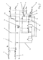
- a house connection station 1 is with a district heating flow 2 and a district heating return 3 connected.
- This house connection station 1 has a heating flow 4 and a heating return 5 on.
- the house connection station 1 has a flow connection 6 for district heating flow 2 and one Return connection 7.1 and 7.2 for district heating return 3 for one Hot water preparation plant that prepares drinking water.
- This water heating system of the house connection station 1 consists of a trained as reheater 8, with the flow connection 6 connected heat exchanger, which is a preheated, via a hot water intermediate pipe 9.1 not shown Drinking water from a cold water connection 10 Target temperature for a hot water supply 11 brings.
- the Temperature of the drinking water heated in the reheater 8 limited to the target temperature by means of a controller 12.
- the temperature of the heating medium from the District heating return 3 before entering the preheater 13 by serving as intermediate heater 14 heat exchanger thermally be raised.
- the heat supply of the as a reheater 14 serving heat exchanger can be from a separate, internal or external energy storage 15 take place.
- the Volume flow in district heating return 3 remains unchanged, which is favorable for the hydraulic design of the system.
- a pump 16 ensures the circulation of the heating medium Buffer 15.
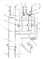
- Fig. 3 shows a circuit where instead of the heating medium the district heating return 3 the domestic hot water after passing the Preheater 13 via a separate energy source Energy storage that is available through internally and / or externally Energy carriers can be charged, further thermally raised becomes.
- This circuit is interesting when energy in the Seasonal heating medium from district heating return 3 is only insignificant on the other hand (e.g. in summer time) but another energy source, such as a solar system lends itself to use.
- a circuit is shown where due to the small thermal levels of a separate heat source (e.g. waste water, Exhaust air) a heat exchanger as the intermediate heater 14 actual preheater 13 is connected upstream. So also in in this case, the drinking water over three warm-up levels Target temperature are brought.
- a separate heat source e.g. waste water, Exhaust air
- this unit can be prefabricated (e.g. on a frame), and only slight changes to the connections are necessary, to implement all of the circuit variants mentioned in FIGS. 1-3 to be able to.
- renewable energy sources solar, waste heat
Landscapes
- Engineering & Computer Science (AREA)
- Physics & Mathematics (AREA)
- Thermal Sciences (AREA)
- Chemical & Material Sciences (AREA)
- Combustion & Propulsion (AREA)
- Mechanical Engineering (AREA)
- General Engineering & Computer Science (AREA)
- Steam Or Hot-Water Central Heating Systems (AREA)
- Central Heating Systems (AREA)
Applications Claiming Priority (2)
| Application Number | Priority Date | Filing Date | Title |
|---|---|---|---|
| DE10311091A DE10311091B4 (de) | 2003-03-07 | 2003-03-07 | Verfahren und Einrichtung zur Reduzierung des Anschlusswertes einer durch Fernwärme gespeisten Hausanschlussstation |
| DE10311091 | 2003-03-07 |
Publications (1)
| Publication Number | Publication Date |
|---|---|
| EP1455140A1 true EP1455140A1 (fr) | 2004-09-08 |
Family
ID=32797914
Family Applications (1)
| Application Number | Title | Priority Date | Filing Date |
|---|---|---|---|
| EP03027014A Withdrawn EP1455140A1 (fr) | 2003-03-07 | 2003-11-22 | Procédé et dispositif pour reduction des valeurs de flux initiales d'une sous-station pour chauffage urbain alimenté par chauffage à distance |
Country Status (2)
| Country | Link |
|---|---|
| EP (1) | EP1455140A1 (fr) |
| DE (1) | DE10311091B4 (fr) |
Cited By (7)
| Publication number | Priority date | Publication date | Assignee | Title |
|---|---|---|---|---|
| FR2893703A1 (fr) * | 2005-11-18 | 2007-05-25 | Vitherm Soc Par Actions Simpli | Installation de production d'eau chaude sanitaire |
| EP2187135A3 (fr) * | 2008-11-18 | 2011-03-30 | SWM Services GmbH | Station de transmission thermique dotée d'une cascade |
| EP2354677A1 (fr) | 2010-02-03 | 2011-08-10 | GEWOFAG Service GmbH | Système à triple ou quadruple conducteur destiné à l'économie d'énergie pour chauffages urbains |
| EP2154436A3 (fr) * | 2008-08-12 | 2014-03-19 | Frank Triesch | Procédé et dispositif de consommation de chaleur |
| EP2778541A1 (fr) | 2013-03-15 | 2014-09-17 | GEWOFAG Gebäude Service GmbH | Circuit destiné à faire baisser la température de retour primaire dans des installations de chauffage à distance |
| US9835385B2 (en) | 2010-02-03 | 2017-12-05 | Gewofag Gebaeude Service Gmbh | Three-conductor and four-conductor system for saving energy in connection with district heat |
| EP4293290A1 (fr) * | 2022-06-14 | 2023-12-20 | Ludwig Langer | Procédé et dispositif de transfert de chaleur |
Families Citing this family (1)
| Publication number | Priority date | Publication date | Assignee | Title |
|---|---|---|---|---|
| EP2876150A1 (fr) | 2013-11-21 | 2015-05-27 | RV Lizenz AG | Réseau d'énergie combiné |
Citations (5)
| Publication number | Priority date | Publication date | Assignee | Title |
|---|---|---|---|---|
| DD204987A1 (de) * | 1982-02-18 | 1983-12-14 | Bauakademie Der Ddr Inst Hlgb | System zur warmwasserbereitung |
| DE4404856A1 (de) * | 1994-02-09 | 1995-08-10 | Wtu Inter Energo Waerme Und Um | Anlage zur kontinuierlichen Warmwasserbereitstellung mittels Fernwärme |
| DE19504730C1 (de) * | 1995-02-06 | 1996-04-11 | Juergen Dipl Ing Lang | Warmwasserbereitungsanlage nach dem Durchflußprinzip mit Leistungsbegrenzung |
| DE19508061A1 (de) * | 1995-02-23 | 1996-08-29 | Hellersdorfer Gebaeudeservice | Steuerung für eine Durchflußwarmwasserbereitungsanlage |
| DE20200163U1 (de) * | 2002-01-07 | 2002-03-28 | Ferroli Industrie GmbH, 01896 Pulsnitz | Schaltungsanordnung zur Trinkwarmwasserbereitung in zentralen Wärmeversorgungssystemen |
-
2003
- 2003-03-07 DE DE10311091A patent/DE10311091B4/de not_active Expired - Fee Related
- 2003-11-22 EP EP03027014A patent/EP1455140A1/fr not_active Withdrawn
Patent Citations (5)
| Publication number | Priority date | Publication date | Assignee | Title |
|---|---|---|---|---|
| DD204987A1 (de) * | 1982-02-18 | 1983-12-14 | Bauakademie Der Ddr Inst Hlgb | System zur warmwasserbereitung |
| DE4404856A1 (de) * | 1994-02-09 | 1995-08-10 | Wtu Inter Energo Waerme Und Um | Anlage zur kontinuierlichen Warmwasserbereitstellung mittels Fernwärme |
| DE19504730C1 (de) * | 1995-02-06 | 1996-04-11 | Juergen Dipl Ing Lang | Warmwasserbereitungsanlage nach dem Durchflußprinzip mit Leistungsbegrenzung |
| DE19508061A1 (de) * | 1995-02-23 | 1996-08-29 | Hellersdorfer Gebaeudeservice | Steuerung für eine Durchflußwarmwasserbereitungsanlage |
| DE20200163U1 (de) * | 2002-01-07 | 2002-03-28 | Ferroli Industrie GmbH, 01896 Pulsnitz | Schaltungsanordnung zur Trinkwarmwasserbereitung in zentralen Wärmeversorgungssystemen |
Cited By (7)
| Publication number | Priority date | Publication date | Assignee | Title |
|---|---|---|---|---|
| FR2893703A1 (fr) * | 2005-11-18 | 2007-05-25 | Vitherm Soc Par Actions Simpli | Installation de production d'eau chaude sanitaire |
| EP2154436A3 (fr) * | 2008-08-12 | 2014-03-19 | Frank Triesch | Procédé et dispositif de consommation de chaleur |
| EP2187135A3 (fr) * | 2008-11-18 | 2011-03-30 | SWM Services GmbH | Station de transmission thermique dotée d'une cascade |
| EP2354677A1 (fr) | 2010-02-03 | 2011-08-10 | GEWOFAG Service GmbH | Système à triple ou quadruple conducteur destiné à l'économie d'énergie pour chauffages urbains |
| US9835385B2 (en) | 2010-02-03 | 2017-12-05 | Gewofag Gebaeude Service Gmbh | Three-conductor and four-conductor system for saving energy in connection with district heat |
| EP2778541A1 (fr) | 2013-03-15 | 2014-09-17 | GEWOFAG Gebäude Service GmbH | Circuit destiné à faire baisser la température de retour primaire dans des installations de chauffage à distance |
| EP4293290A1 (fr) * | 2022-06-14 | 2023-12-20 | Ludwig Langer | Procédé et dispositif de transfert de chaleur |
Also Published As
| Publication number | Publication date |
|---|---|
| DE10311091A1 (de) | 2004-09-23 |
| DE10311091B4 (de) | 2004-11-25 |
Similar Documents
| Publication | Publication Date | Title |
|---|---|---|
| DE3242903C2 (fr) | ||
| DE102008057908A1 (de) | Wärmeübergabestation mit Kaskade | |
| DE102019000430B4 (de) | Verfahren zur Erreichung sehr niedriger Rücklauftemperaturen mittels einer Wärmepumpe, Heizanordnung zur Durchführung des Verfahrens, sowie System für Wärme- und Kälteverteilnetze | |
| EP2416073A2 (fr) | Procédé et dispositif destinés au chauffage d'un fluide dans une mémoire tampon | |
| DE10311091B4 (de) | Verfahren und Einrichtung zur Reduzierung des Anschlusswertes einer durch Fernwärme gespeisten Hausanschlussstation | |
| DE102008033063B4 (de) | Verfahren und Vorrichtung zur zentralen Warmwasserversorgung | |
| DE10226870B4 (de) | Hausanschlussstation für Fernwärme | |
| DE102010019727A1 (de) | Verfahren und Vorrichtung zur Übertragung von Wärme | |
| DE19504730C1 (de) | Warmwasserbereitungsanlage nach dem Durchflußprinzip mit Leistungsbegrenzung | |
| DE19508061A1 (de) | Steuerung für eine Durchflußwarmwasserbereitungsanlage | |
| DE102016102718B4 (de) | Trinkwassererwärmungssystem | |
| DE10320835B4 (de) | Verfahren und Einrichtung zur lastabhängigen Steuerung des Volumenstromes in einem Heizkreis einer nach dem Durchlaufprinzip arbeitenden Einrichtung zur Warmwasserbereitstellung | |
| AT377598B (de) | Warmwasserleitungssystem | |
| EP0961082B1 (fr) | Installation de chauffage et de préparation d'eau chaude | |
| EP0880659A1 (fr) | Regulateur solaire a effet modulateur | |
| DE69105742T2 (de) | Zentralheizungsanlage. | |
| EP0171014B1 (fr) | Procédé et dispositif d'amélioration du rendement d'une centrale thermique, basé sur la capacité de stockage thermique du système de chauffage à distance | |
| EP2226571A1 (fr) | Agencement et procédé de chauffage d'eau potable pour un site de consommation, respectivement, de distribution | |
| DE69620778T2 (de) | Verfahren und vorrichtung zur erzeugung von kälte und wärme | |
| AT401576B (de) | Verfahren zur nutzung von nachwärme in fernwärmeversorgungsanlagen | |
| DE102012109570A1 (de) | Vorrichtung zur Erwärmung von Brauchwasser | |
| DE2841888A1 (de) | Solarheizung | |
| DE19517053A1 (de) | Verfahren zum Betrieb eines Wärmenetzes zur zentralen Wärmeversorgung in Gebäuden | |
| DE4404856C2 (de) | Anlage zur kontinuierlichen Warmwasserbereitstellung mittels Fernwärme | |
| DE102013112952A1 (de) | System und Verfahren zur Erwärmung von Trink- und Heizwasser |
Legal Events
| Date | Code | Title | Description |
|---|---|---|---|
| PUAI | Public reference made under article 153(3) epc to a published international application that has entered the european phase |
Free format text: ORIGINAL CODE: 0009012 |
|
| AK | Designated contracting states |
Kind code of ref document: A1 Designated state(s): AT BE BG CH CY CZ DE DK EE ES FI FR GB GR HU IE IT LI LU MC NL PT RO SE SI SK TR |
|
| AX | Request for extension of the european patent |
Extension state: AL LT LV MK |
|
| 17P | Request for examination filed |
Effective date: 20050128 |
|
| AKX | Designation fees paid |
Designated state(s): AT BE BG CH CY CZ DE DK EE ES FI FR GB GR HU IE IT LI LU MC NL PT RO SE SI SK TR |
|
| 17Q | First examination report despatched |
Effective date: 20061011 |
|
| GRAP | Despatch of communication of intention to grant a patent |
Free format text: ORIGINAL CODE: EPIDOSNIGR1 |
|
| INTG | Intention to grant announced |
Effective date: 20130917 |
|
| STAA | Information on the status of an ep patent application or granted ep patent |
Free format text: STATUS: THE APPLICATION IS DEEMED TO BE WITHDRAWN |
|
| 18D | Application deemed to be withdrawn |
Effective date: 20140128 |