EP1455147A2 - Sonnenkollektor für Wassererhitzer - Google Patents
Sonnenkollektor für Wassererhitzer Download PDFInfo
- Publication number
- EP1455147A2 EP1455147A2 EP04290591A EP04290591A EP1455147A2 EP 1455147 A2 EP1455147 A2 EP 1455147A2 EP 04290591 A EP04290591 A EP 04290591A EP 04290591 A EP04290591 A EP 04290591A EP 1455147 A2 EP1455147 A2 EP 1455147A2
- Authority
- EP
- European Patent Office
- Prior art keywords
- solar collector
- ribs
- shells
- exchanger
- heat
- Prior art date
- Legal status (The legal status is an assumption and is not a legal conclusion. Google has not performed a legal analysis and makes no representation as to the accuracy of the status listed.)
- Withdrawn
Links
Images


Classifications
-
- F—MECHANICAL ENGINEERING; LIGHTING; HEATING; WEAPONS; BLASTING
- F24—HEATING; RANGES; VENTILATING
- F24S—SOLAR HEAT COLLECTORS; SOLAR HEAT SYSTEMS
- F24S80/00—Details, accessories or component parts of solar heat collectors not provided for in groups F24S10/00-F24S70/00
- F24S80/40—Casings
- F24S80/45—Casings characterised by the material
- F24S80/457—Casings characterised by the material made of plastics
-
- F—MECHANICAL ENGINEERING; LIGHTING; HEATING; WEAPONS; BLASTING
- F24—HEATING; RANGES; VENTILATING
- F24S—SOLAR HEAT COLLECTORS; SOLAR HEAT SYSTEMS
- F24S10/00—Solar heat collectors using working fluids
- F24S10/50—Solar heat collectors using working fluids the working fluids being conveyed between plates
- F24S10/501—Solar heat collectors using working fluids the working fluids being conveyed between plates having conduits of plastic material
-
- F—MECHANICAL ENGINEERING; LIGHTING; HEATING; WEAPONS; BLASTING
- F24—HEATING; RANGES; VENTILATING
- F24S—SOLAR HEAT COLLECTORS; SOLAR HEAT SYSTEMS
- F24S10/00—Solar heat collectors using working fluids
- F24S10/50—Solar heat collectors using working fluids the working fluids being conveyed between plates
- F24S10/504—Solar heat collectors using working fluids the working fluids being conveyed between plates having conduits formed by paired non-plane plates
-
- F—MECHANICAL ENGINEERING; LIGHTING; HEATING; WEAPONS; BLASTING
- F24—HEATING; RANGES; VENTILATING
- F24S—SOLAR HEAT COLLECTORS; SOLAR HEAT SYSTEMS
- F24S80/00—Details, accessories or component parts of solar heat collectors not provided for in groups F24S10/00-F24S70/00
- F24S80/30—Arrangements for connecting the fluid circuits of solar collectors with each other or with other components, e.g. pipe connections; Fluid distributing means, e.g. headers
-
- F—MECHANICAL ENGINEERING; LIGHTING; HEATING; WEAPONS; BLASTING
- F24—HEATING; RANGES; VENTILATING
- F24S—SOLAR HEAT COLLECTORS; SOLAR HEAT SYSTEMS
- F24S80/00—Details, accessories or component parts of solar heat collectors not provided for in groups F24S10/00-F24S70/00
- F24S80/60—Thermal insulation
-
- Y—GENERAL TAGGING OF NEW TECHNOLOGICAL DEVELOPMENTS; GENERAL TAGGING OF CROSS-SECTIONAL TECHNOLOGIES SPANNING OVER SEVERAL SECTIONS OF THE IPC; TECHNICAL SUBJECTS COVERED BY FORMER USPC CROSS-REFERENCE ART COLLECTIONS [XRACs] AND DIGESTS
- Y02—TECHNOLOGIES OR APPLICATIONS FOR MITIGATION OR ADAPTATION AGAINST CLIMATE CHANGE
- Y02B—CLIMATE CHANGE MITIGATION TECHNOLOGIES RELATED TO BUILDINGS, e.g. HOUSING, HOUSE APPLIANCES OR RELATED END-USER APPLICATIONS
- Y02B10/00—Integration of renewable energy sources in buildings
- Y02B10/20—Solar thermal
-
- Y—GENERAL TAGGING OF NEW TECHNOLOGICAL DEVELOPMENTS; GENERAL TAGGING OF CROSS-SECTIONAL TECHNOLOGIES SPANNING OVER SEVERAL SECTIONS OF THE IPC; TECHNICAL SUBJECTS COVERED BY FORMER USPC CROSS-REFERENCE ART COLLECTIONS [XRACs] AND DIGESTS
- Y02—TECHNOLOGIES OR APPLICATIONS FOR MITIGATION OR ADAPTATION AGAINST CLIMATE CHANGE
- Y02E—REDUCTION OF GREENHOUSE GAS [GHG] EMISSIONS, RELATED TO ENERGY GENERATION, TRANSMISSION OR DISTRIBUTION
- Y02E10/00—Energy generation through renewable energy sources
- Y02E10/40—Solar thermal energy, e.g. solar towers
- Y02E10/44—Heat exchange systems
Definitions
- the present invention relates to a solar collector for water heater intended to equip a hot water production system sanitary or heating, the sensor being able to recover solar energy and transmit it to a heat transfer fluid which can be the water intended to be used or another fluid.
- solar collectors of this type generally made of a metallic material which may include for example a absorber device consisting of a copper tube carrying a plurality aluminum fins to increase the exchange surface.
- the tube which acts as a heat exchanger, is generally mounted in a support box leaving a space playing a role of air space between the tube, heat exchanger, fitted with its fins, and a plate of translucent cover letting in the rays of the sun and increasing the temperature of the air gap in contact with the tube greenhouse heat exchanger.
- Sensors of this type have a number disadvantages, due to their mainly metallic structure. Indeed, the manufacture of these devices is made complex by the assembly and welding problems. The weight of the set is high, which results in constraints for the installation of these sensors, for example on the roofs of buildings. Moreover, the overall thickness of this type of sensor is relatively important (from 10 to 20 cm), due to the need to leave an air vacuum remains on each side of the fin tube, heat exchanger heat.
- US Patent 4,397,305 describes a solar collector comprising a solar collector defining a hollow frame and a plurality passages for the heat transfer fluid, the assembly being produced by molding by centrifugation or heat blowing, in one piece, seamless or bonded. It is further specified in this document, that it is essential to communicate the hollow frame with the atmosphere outside, so as to create a cooling air circulation in the hollow frame and the air gap which is above the manifold passages, so as to maintain the air temperature at an acceptable level below about 104 ° C.
- the object of the present invention is to eliminate the drawbacks known devices and to provide a solar collector which is particularly simple to manufacture and whose performance is also particularly important.
- the invention also relates to a solar collector, very thin and very light, which can therefore be easily installed, for example on the roofs of buildings.
- the solar collector for water heaters of the invention is of the type comprising a heat exchanger made of a synthetic material molded, having a plurality of passages inside which can circulate a heat transfer fluid and a cover plate translucent fixed on the exchanger with a spacing.
- the heat exchanger heat constitutes the support frame of the sensor excluding any additional room.
- the exchanger consists of two identical half-shells provided with parallel longitudinal central ribs projecting and a larger projecting edge rib than a central rib.
- the two half-shells are glued or heat-sealed together so that the central ribs define the passages for the heat transfer fluid and that the ribs respective border lines define a sealed hollow border frame filled with insulating air confined to the periphery of the exchanger.
- the half-shells being identical can be manufactured using of the same mold, preferably from a fabric based on carbon or glass, prepreg with synthetic resin.
- the molding can be done by press by forming in a mold.
- Insulating air is trapped inside the border frame hollow at the time of molding.
- the insulation achieved by air confined to inside the border frame that surrounds the exchange area thermal over its entire periphery is an important characteristic because it allows a significant increase in the return on exchange thermal.
- the projecting longitudinal ribs allow obtaining heat transfer fluid passages preferably having a thickness between 5 and 10 mm, ideally 8 mm so as to reduce pressure losses while increasing the transfer efficiency of heat.
- the temperature of the heat transfer fluid is generally between 30 ° C and 90 ° C, more particularly about 80 ° C, even if the air temperature inside the sensor can be much higher.
- the two half-shells also comprise two projecting transverse ribs of the same dimension as one of the longitudinal ribs and defining on two sides of the exchanger, two collecting channels in communication with the ends of the aforementioned passages.
- At least two added cannulas are advantageously provided for the inlet and outlet of the heat transfer fluid, the cannulas sealingly passing through the hollow border frame and opening in the collecting channels.
- Each cannula can be fitted with a threaded captive nut for connection with the pipe for using the heat transfer fluid, which can be water.
- the cover plate is glued or heat sealed on the hollow border frame to define the upper face of the sensor.
- An insulating material is preferably placed on the face bottom of the sensor.
- the insulating material is advantageously delimited by the frame hollow border and has a thickness such that it does not substantially not protruding from said border frame.
- a solar water heater according to the invention can comprise a single solar collector or at least two collectors as previously described, connected together in series.
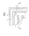
- a half-shell 1 has a generally rectangular shape.
- a plurality of parallel longitudinal ribs 2 are made, projecting from zones 3 located between the different ribs 2.
- the ribs 2 constitute, after assembly of half-shells identical, as will be seen below, passages for a coolant.
- a projecting rib 4 is disposed over the entire periphery of the half-shell 1, and constitutes a border for this last.
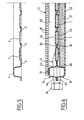
- the protruding dimension of the edge rib 4 is significantly larger than the protruding dimension of the ribs longitudinal 2, as can be seen in particular in the view in section of FIG. 5.
- the protruding dimension of border rib 4 is about four times larger than the protruding dimension of the longitudinal ribs 2.
- the half-shell 1 also comprises, in the vicinity of its transverse edges and inside with respect to the edge rib 4, two transverse ribs 5 projecting, having the same protruding dimensions as the longitudinal ribs 2.
- One of these transverse ribs 5 is visible in the sectional view of FIG. 3.
- the half-shell 1 can be produced by molding a material synthetic, preferably loaded with a particulate material heat absorbing, such as carbon black or filament black stuck in glass, drowned in synthetic resin. he is also possible to use a woven carbon fiber material, which is then impregnated with a synthetic resin, then introduced into a forming press. The manufacture of the half-shell 1 can be done automatically and at high speed.
- the half-shell as well obtained has a total overall thickness of 20 to 35 mm, with walls having a thickness of 2 to 3 mm. It thus constitutes a particularly light element.
- two half-shells are used identical, such as the half-shell 1 visible in FIG. 1.
- These two identical half-shells, referenced la and 1b in FIGS. 4 and 6, are fixed to each other by gluing or heat sealing along the contact zones formed by the longitudinal plane zones 3 se located between the parallel longitudinal central ribs 2.
- the two respective edge ribs 4a and 4b of the half-shells identical 1a and 1b form a sealed frame filled with air insulator confined to manufacturing and placed at the periphery of the sensor.
- the planar extreme edges 6a, 6b of the half-shells 1a, 1b are also glued or heat-sealed over the entire periphery of the frame border formed by the border ribs 4a, 4b.
- Each of the collecting channels 8 leads to its two ends in a nozzle 9 formed by a projecting zone 10a, 10b practiced on each of the half-shells 1 in the vicinity of at least two angles of its rectangular shape, as we can see in particular in Figure 2.
- the tip 9 visible in section in Figure 7 is formed by the respective projecting portions 10a and 10b of the two half-shells identical 1a and 1b.
- a cylindrical cannula 11 can thus be added during manufacture at the location of the nozzle 9 between the two half-shells 1a and 1b, by being fixed to these by gluing or heat sealing according to the material of said cannula 11.
- the internal end 12 of the cannula 11 comes into the interior of the nozzle 9 and is sealingly fixed to the walls 10a, 10b of it.
- part 13 of the cannula 11 is fixed on a projecting edge 14a, 14b of each of the half-shells 1a, 1b.
- the FIG. 2 shows in particular the projecting shape of this portion 14.
- the outer end of the cannula 11 has a collar 15 which allows the captive maintenance of a threaded nut 16 used for connection with a pipe for using the heat transfer fluid. Thanks to the fixing by gluing or heat sealing of the cannula 11, this can pass tightly through the hollow border frame defined by the ribs 4a, 4b, as illustrated in FIG. 7.
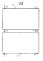
- the solar collector not only includes the heat exchanger heat constituted, as was said above, by the association of two identical half-shells 1a and 1b, but also a plate of translucent cover 17 visible in FIGS. 4 and 6 having substantially the same dimensions as one of the half-shells 1.
- the plate 17 is made of synthetic material translucent and includes a multitude of parallel 18 visible channels in section in FIG. 6.
- the plate 17 is fixed for example by bonding by means of a bead of glue 19 around the entire periphery of the edge rib 4a of the half-shell 1a.
- an air gap 20 is located thus defined between the cover plate 17 and the outer surface longitudinal ribs 2a which delimit the passages 17 for the coolant.
- a layer 21 of an insulating material which occupies the space delimited by the border frame of the border rib 4b, as seen in Figures 4 and 6.
- the thickness of the insulating layer 21 is such that it does not protrude beyond the projection of the edge rib 4b.
- the insulating layer 21 can be maintained by means of a plate lower closure 22 bonded to the lower surface of the border rib 4b.
- the material layer insulator 21 does not come into contact with the lower surface of the longitudinal ribs 2b.
- a solar collector constituted as shown partially in section in Figures 4 and 6, has the advantage of particularly simple to manufacture as indicated previously, very light and thick particularly reduced.
- the volume of air confined inside the defined border frame by the ribs 4a, 4b, is an important characteristic of the invention making it possible to increase the temperature of the air in the air gap 20, and therefore the thermal efficiency of the solar collector.
- the tightness of the volume defined inside the two ribs of border 4a, 4b, is ensured by bonding or heat-sealing the two half-shells 1a, 1b, as well as by the particular structure illustrated in Figure 7, which allows the sealed passage of the cannulas 11 to across the enclosed space of the border frame.
- two cannulas are provided at the corners diagonally opposite.
- four cannulas 11 of the same type can be arranged respectively at each of the angles of the sensor.
- One of these cannulas is advantageously used as an inlet for the heat transfer fluid, while another cannula located in the diagonally opposite corner, can be used as an outlet for the heat transfer fluid.
- the circulation of heat transfer fluid is then shown as shown by the arrows 23 in Figure 1.
- the other cannulas, which are not used for circulation of the heat transfer fluid are either closed by a plug threaded, either used to purge the air possibly contained in the passages for the heat transfer fluid.
- a first sensor 24 is connected by its output 25 to the input 26 of a second sensor 27, of which the outlet is in the diagonally opposite corner 28.
- the following materials may be mentioned: injected polycarbonate, polycarbonate copolymer, polyphenylene ether (PPE), polymethyl methacrylate (PMMA), phenylene polysulfides (PPS), polyetherimide (PEI) or an assembly and complex of synthetic materials, containing carbon or glass fibers.
- PPE polyphenylene ether
- PMMA polymethyl methacrylate
- PPS phenylene polysulfides
- PEI polyetherimide
- the solar collector according to the invention can be associated, as conventional sensors, a control loop and a balloon or a storage tank to store the hot water thus produced.
- the storage tank can be fitted with an exchanger and a electrical resistance, depending on the applications.
Landscapes
- Engineering & Computer Science (AREA)
- Chemical & Material Sciences (AREA)
- Life Sciences & Earth Sciences (AREA)
- Sustainable Development (AREA)
- Sustainable Energy (AREA)
- Thermal Sciences (AREA)
- Physics & Mathematics (AREA)
- Combustion & Propulsion (AREA)
- Mechanical Engineering (AREA)
- General Engineering & Computer Science (AREA)
- Photovoltaic Devices (AREA)
- Roof Covering Using Slabs Or Stiff Sheets (AREA)
- Heat-Exchange Devices With Radiators And Conduit Assemblies (AREA)
- Heat-Pump Type And Storage Water Heaters (AREA)
Applications Claiming Priority (2)
| Application Number | Priority Date | Filing Date | Title |
|---|---|---|---|
| FR0302740A FR2852087B1 (fr) | 2003-03-06 | 2003-03-06 | Capteur solaire pour chauffe-eau |
| FR0302740 | 2003-03-06 |
Publications (2)
| Publication Number | Publication Date |
|---|---|
| EP1455147A2 true EP1455147A2 (de) | 2004-09-08 |
| EP1455147A3 EP1455147A3 (de) | 2011-07-13 |
Family
ID=32799637
Family Applications (1)
| Application Number | Title | Priority Date | Filing Date |
|---|---|---|---|
| EP04290591A Withdrawn EP1455147A3 (de) | 2003-03-06 | 2004-03-04 | Sonnenkollektor für Wassererhitzer |
Country Status (3)
| Country | Link |
|---|---|
| US (1) | US7431030B2 (de) |
| EP (1) | EP1455147A3 (de) |
| FR (1) | FR2852087B1 (de) |
Cited By (5)
| Publication number | Priority date | Publication date | Assignee | Title |
|---|---|---|---|---|
| ITBO20080648A1 (it) * | 2008-10-21 | 2010-04-22 | Polo S R L | Dispositivo a collettore solare |
| EP2284452A1 (de) * | 2009-08-12 | 2011-02-16 | Roth Werke GmbH | Solarabsorber und modulares System |
| EP2369260A3 (de) * | 2010-03-15 | 2012-10-03 | Dr. Doll Holding GmbH | Sonnenkollektor |
| EP2148152A3 (de) * | 2008-07-26 | 2013-11-20 | Robert Bosch GmbH | Solarkollektor und dessen Herstellungsverfahren |
| EP4421406A1 (de) | 2023-02-23 | 2024-08-28 | OKU Obermaier GmbH, Kunststoff und Metall | Solarabsorber-modul |
Families Citing this family (22)
| Publication number | Priority date | Publication date | Assignee | Title |
|---|---|---|---|---|
| SG127761A1 (en) * | 2005-05-24 | 2006-12-29 | Chen Qixin | Fluid-flow apparatus as solar heat collector |
| US20070084460A1 (en) * | 2005-05-31 | 2007-04-19 | Vaughn Beckman | Solar collector |
| US8997901B2 (en) * | 2006-05-11 | 2015-04-07 | Ford Global Technologies, Llc | Vehicular body panel energy generator system |
| WO2007138117A1 (es) * | 2006-05-24 | 2007-12-06 | Grupo Antolin-Ingenieria, S.A. | Placa absorbedor para colector solar, su método de fabricación, y colector solar |
| US20080029149A1 (en) * | 2006-08-02 | 2008-02-07 | Daniel Simon | Method and apparatus for arranging a solar cell and reflector |
| USD560605S1 (en) * | 2006-09-20 | 2008-01-29 | Readysolar, Inc. | Solar panel frame |
| USD560606S1 (en) * | 2006-09-29 | 2008-01-29 | Readysolar, Inc. | Framed solar panel |
| ITMO20070048A1 (it) * | 2007-02-15 | 2008-08-16 | Jcp S R L | Struttura di protezione |
| US8096295B1 (en) | 2007-08-28 | 2012-01-17 | Eyal Victor A | Solar panel having polycarbonate sheet covering |
| US7604003B2 (en) * | 2007-10-17 | 2009-10-20 | Autumn Solar Installations Pty Limited | Solar panel |
| CH705211B1 (fr) * | 2007-12-18 | 2013-01-15 | Hayek Engineering Ag | Véhicule automobile électrique solaire. |
| ITMI20081184A1 (it) * | 2008-06-27 | 2009-12-28 | Elletiemme S R L | Dispositivo di copertura per tetti e simili |
| US8353286B2 (en) * | 2009-06-23 | 2013-01-15 | Yangsong Li | Solar water heater and method |
| EP2516939A4 (de) * | 2009-12-24 | 2014-10-29 | Dolav Plastic Products Cooperative Soc Ltd | Solarboiler |
| IT1401122B1 (it) * | 2010-07-15 | 2013-07-12 | Fardelli | Pannello solare termico ad elevato rendimento, particolarmente per il riscaldamento di ambienti e/o per la produzione di acqua calda per usi igienico-sanitari. |
| NO331445B1 (no) * | 2010-11-16 | 2012-01-02 | Hiform As | Varmeveksler |
| HUP1000641A2 (en) | 2010-11-30 | 2012-08-28 | Pal Molnar | Heat exchanger panel and its production method |
| US8955509B2 (en) * | 2011-08-29 | 2015-02-17 | Sunvelope Solar, Inc. | Solar water heating systems and methods of making and using the same |
| US20130333310A1 (en) * | 2012-06-15 | 2013-12-19 | Mas S.R.L. | Modular Structure, Modular Panel To Make Said Modular Structure And Corresponding Method To Make Said Modular Structure |
| US9915444B2 (en) | 2013-03-13 | 2018-03-13 | Helios Products, Llc | Translucent plastic solar thermal collector |
| EP2801766A1 (de) * | 2013-05-10 | 2014-11-12 | voestalpine Polynorm BV | Solarkollektor zur Erwärmung eines Wärmeträgers |
| US10727552B2 (en) * | 2015-11-04 | 2020-07-28 | Ford Global Technologies, Llc | Heat exchanger plate for electrified vehicle battery packs |
Family Cites Families (17)
| Publication number | Priority date | Publication date | Assignee | Title |
|---|---|---|---|---|
| FR1094368A (fr) * | 1953-11-13 | 1955-05-20 | Insol Maroc | Perfectionnements apportés aux chauffe-eau solaires et aux panneaux utilisables notamment comme panneaux absorbants pour ces chauffe-eau |
| US4178910A (en) * | 1976-06-25 | 1979-12-18 | Gramer Eben J | Solar collector and system for mounting a plurality of solar collectors on a surface |
| US4146012A (en) * | 1976-07-19 | 1979-03-27 | Acurex Corporation | Solar heat exchange panel |
| US4147155A (en) * | 1977-01-19 | 1979-04-03 | Krafft Frederick G | Device for collecting solar energy |
| DE2712387A1 (de) * | 1977-03-22 | 1978-10-05 | Roth Kg Metallwerk | Sonnenkollektor |
| US4290413A (en) * | 1978-05-25 | 1981-09-22 | Libbey-Owens-Ford Company | Solar energy collector |
| US4278072A (en) * | 1978-08-21 | 1981-07-14 | Rykal Solar Corporation | Forced air solar heating system |
| US4257398A (en) * | 1979-03-26 | 1981-03-24 | Watson W Keith R | High efficiency solar collector |
| US4310182A (en) * | 1979-06-15 | 1982-01-12 | Sealed Air Corporation | Internal couplings for plastic solar collectors and the like |
| JPS56108050A (en) * | 1980-01-30 | 1981-08-27 | Tokyo Electric Co Ltd | Solar heat collector |
| US4423000A (en) * | 1980-10-17 | 1983-12-27 | Syoichi Teraoka | Method for molding hollow plastic articles |
| US4397305A (en) | 1981-10-14 | 1983-08-09 | Solaroi, Inc. | Solar heating panel |
| JPS598736B2 (ja) * | 1981-10-15 | 1984-02-27 | 松下電工株式会社 | 太陽熱コレクタ− |
| GB2147407B (en) * | 1983-09-29 | 1987-05-07 | Janson Goesta | Solar heaters |
| US5018263A (en) * | 1989-10-02 | 1991-05-28 | Stern Melvin J | Method for making a metal screen door frame |
| US6008448A (en) * | 1998-10-15 | 1999-12-28 | Space Systems/Loral, Inc. | Solar panel array with stepped taper |
| FR2787868B1 (fr) | 1998-12-29 | 2001-06-01 | Pierre Jean Nocera | Capteur solaire pour chauffe-eau |
-
2003
- 2003-03-06 FR FR0302740A patent/FR2852087B1/fr not_active Expired - Fee Related
-
2004
- 2004-03-04 EP EP04290591A patent/EP1455147A3/de not_active Withdrawn
- 2004-03-05 US US10/793,274 patent/US7431030B2/en not_active Expired - Fee Related
Cited By (6)
| Publication number | Priority date | Publication date | Assignee | Title |
|---|---|---|---|---|
| EP2148152A3 (de) * | 2008-07-26 | 2013-11-20 | Robert Bosch GmbH | Solarkollektor und dessen Herstellungsverfahren |
| ITBO20080648A1 (it) * | 2008-10-21 | 2010-04-22 | Polo S R L | Dispositivo a collettore solare |
| EP2284452A1 (de) * | 2009-08-12 | 2011-02-16 | Roth Werke GmbH | Solarabsorber und modulares System |
| EP2369260A3 (de) * | 2010-03-15 | 2012-10-03 | Dr. Doll Holding GmbH | Sonnenkollektor |
| EP4421406A1 (de) | 2023-02-23 | 2024-08-28 | OKU Obermaier GmbH, Kunststoff und Metall | Solarabsorber-modul |
| DE102023104486A1 (de) | 2023-02-23 | 2024-08-29 | oku - Obermaier GmbH, Kunststoff und Metall | Solarabsorber-Modul |
Also Published As
| Publication number | Publication date |
|---|---|
| US7431030B2 (en) | 2008-10-07 |
| FR2852087A1 (fr) | 2004-09-10 |
| US20040255932A1 (en) | 2004-12-23 |
| EP1455147A3 (de) | 2011-07-13 |
| FR2852087B1 (fr) | 2006-12-29 |
Similar Documents
| Publication | Publication Date | Title |
|---|---|---|
| EP1455147A2 (de) | Sonnenkollektor für Wassererhitzer | |
| FR2521700A1 (fr) | Collecteur d'energie solaire | |
| CA2329638C (fr) | Panneau solaire et dispositif de collecte d'energie solaire | |
| EP3408869B1 (de) | Fotovoltaisches und thermisches solarpaneel | |
| FR2461901A1 (fr) | Capteur d'energie solaire, chauffe-eau et dispositif de chauffage avec pompe a chaleur comportant ledit capteur | |
| FR2526146A1 (fr) | Echangeur de chaleur a element d'echange dispose a l'interieur d'un caisson | |
| FR2787868A1 (fr) | Capteur solaire pour chauffe-eau | |
| FR2462671A1 (fr) | Capteur solaire, concu particulierement pour facades de batiments | |
| EP0012678B1 (de) | Solarenergiekollektor | |
| EP2623909B1 (de) | Fotovoltaikpaneel mit Wärmerückgewinnung | |
| EP2423630B1 (de) | Wärmeaustauschvorrichtung | |
| CA1132020A (fr) | Capteur solaire | |
| EP0003478A1 (de) | Sonnenenergiekollektor | |
| EP0148695A2 (de) | Solarwassererhitzer mit direktem Wasserdurchgang und Verfahren zu seiner Herstellung | |
| EP2299185A2 (de) | Elektrischer Speicherheizkörper und/oder Trägheitsheizkörper | |
| EP0289438B1 (de) | Solarer Speicher-Kollektor | |
| FR2850451A1 (fr) | Echangeur de chaleur a condensation, a enveloppe plastique | |
| FR2955705A1 (fr) | Module de production d'energie mixte photovoltaique et thermique a partir du rayonnement solaire, et installation equipee de tels modules | |
| FR2936863A1 (fr) | Installation de geothermie. | |
| FR2935786A1 (fr) | Capteur solaire thermique | |
| FR2481785A1 (fr) | Surfaces pour capteur solaire | |
| FR2567252A1 (fr) | Generateur helio-thermique a faible concentration et rendement eleve | |
| FR2476812A1 (fr) | Capteur solaire a panneau autoporteur | |
| FR2492954A1 (fr) | Materiau composite souple pour la confection de capteurs solaires a haut rendement | |
| FR2574912A2 (fr) | Chauffe-eau solaire pour le chauffage et le stockage par passage direct de l'eau et son procede de fabrication |
Legal Events
| Date | Code | Title | Description |
|---|---|---|---|
| PUAI | Public reference made under article 153(3) epc to a published international application that has entered the european phase |
Free format text: ORIGINAL CODE: 0009012 |
|
| AK | Designated contracting states |
Kind code of ref document: A2 Designated state(s): AT BE BG CH CY CZ DE DK EE ES FI FR GB GR HU IE IT LI LU MC NL PL PT RO SE SI SK TR |
|
| AX | Request for extension of the european patent |
Extension state: AL HR LT LV MK |
|
| RAP1 | Party data changed (applicant data changed or rights of an application transferred) |
Owner name: SAINT-GOBAIN VETROTEX FRANCE S.A. |
|
| RIN1 | Information on inventor provided before grant (corrected) |
Inventor name: NOCERA, PIERRE JEAN |
|
| PUAL | Search report despatched |
Free format text: ORIGINAL CODE: 0009013 |
|
| AK | Designated contracting states |
Kind code of ref document: A3 Designated state(s): AT BE BG CH CY CZ DE DK EE ES FI FR GB GR HU IE IT LI LU MC NL PL PT RO SE SI SK TR |
|
| AX | Request for extension of the european patent |
Extension state: AL LT LV MK |
|
| RIC1 | Information provided on ipc code assigned before grant |
Ipc: F24J 2/20 20060101AFI20040617BHEP |
|
| RIC1 | Information provided on ipc code assigned before grant |
Ipc: F24J 2/20 20060101AFI20110629BHEP |
|
| AKX | Designation fees paid |
Designated state(s): AT BE BG CH CY CZ DE DK EE ES FI FR GB GR HU IE IT LI LU MC NL PL PT RO SE SI SK TR |
|
| AXX | Extension fees paid |
Extension state: MK Payment date: 20040526 Extension state: LV Payment date: 20040526 Extension state: LT Payment date: 20040526 Extension state: AL Payment date: 20040526 |
|
| STAA | Information on the status of an ep patent application or granted ep patent |
Free format text: STATUS: THE APPLICATION IS DEEMED TO BE WITHDRAWN |
|
| 18D | Application deemed to be withdrawn |
Effective date: 20120114 |