EP1455206A1 - Verfahren zur Herstellung einer photo-kristallinen Plastikfaser - Google Patents
Verfahren zur Herstellung einer photo-kristallinen Plastikfaser Download PDFInfo
- Publication number
- EP1455206A1 EP1455206A1 EP04300098A EP04300098A EP1455206A1 EP 1455206 A1 EP1455206 A1 EP 1455206A1 EP 04300098 A EP04300098 A EP 04300098A EP 04300098 A EP04300098 A EP 04300098A EP 1455206 A1 EP1455206 A1 EP 1455206A1
- Authority
- EP
- European Patent Office
- Prior art keywords
- composition
- photo
- optical fiber
- holes
- reactive
- Prior art date
- Legal status (The legal status is an assumption and is not a legal conclusion. Google has not performed a legal analysis and makes no representation as to the accuracy of the status listed.)
- Withdrawn
Links
- 238000004519 manufacturing process Methods 0.000 title claims description 31
- 229920001887 crystalline plastic Polymers 0.000 title claims description 23
- 239000000835 fiber Substances 0.000 title description 23
- 238000002347 injection Methods 0.000 claims abstract description 34
- 239000007924 injection Substances 0.000 claims abstract description 34
- 239000007788 liquid Substances 0.000 claims abstract description 32
- 238000000034 method Methods 0.000 claims abstract description 25
- 229920000642 polymer Polymers 0.000 claims abstract description 24
- 230000005855 radiation Effects 0.000 claims abstract description 24
- 150000001875 compounds Chemical class 0.000 claims abstract description 10
- 239000000203 mixture Substances 0.000 claims description 105
- 239000011797 cavity material Substances 0.000 claims description 33
- 239000013308 plastic optical fiber Substances 0.000 claims description 27
- 230000000737 periodic effect Effects 0.000 claims description 13
- 239000002904 solvent Substances 0.000 claims description 10
- DNIAPMSPPWPWGF-UHFFFAOYSA-N Propylene glycol Chemical compound CC(O)CO DNIAPMSPPWPWGF-UHFFFAOYSA-N 0.000 claims description 9
- 239000011159 matrix material Substances 0.000 claims description 7
- JHIVVAPYMSGYDF-UHFFFAOYSA-N cyclohexanone Chemical compound O=C1CCCCC1 JHIVVAPYMSGYDF-UHFFFAOYSA-N 0.000 claims description 6
- 239000007789 gas Substances 0.000 claims description 6
- NIXOWILDQLNWCW-UHFFFAOYSA-N acrylic acid group Chemical group C(C=C)(=O)O NIXOWILDQLNWCW-UHFFFAOYSA-N 0.000 claims description 5
- 230000009471 action Effects 0.000 claims description 5
- 238000009826 distribution Methods 0.000 claims description 5
- 125000000391 vinyl group Chemical group [H]C([*])=C([H])[H] 0.000 claims description 5
- 229920002554 vinyl polymer Polymers 0.000 claims description 5
- XKRFYHLGVUSROY-UHFFFAOYSA-N Argon Chemical compound [Ar] XKRFYHLGVUSROY-UHFFFAOYSA-N 0.000 claims description 4
- IJGRMHOSHXDMSA-UHFFFAOYSA-N Atomic nitrogen Chemical compound N#N IJGRMHOSHXDMSA-UHFFFAOYSA-N 0.000 claims description 4
- 238000010438 heat treatment Methods 0.000 claims description 4
- 239000000463 material Substances 0.000 claims description 4
- 239000000178 monomer Substances 0.000 claims description 4
- PUPZLCDOIYMWBV-UHFFFAOYSA-N (+/-)-1,3-Butanediol Chemical compound CC(O)CCO PUPZLCDOIYMWBV-UHFFFAOYSA-N 0.000 claims description 3
- 229920002988 biodegradable polymer Polymers 0.000 claims description 3
- 239000004621 biodegradable polymer Substances 0.000 claims description 3
- 125000002256 xylenyl group Chemical class C1(C(C=CC=C1)C)(C)* 0.000 claims description 3
- RZKSECIXORKHQS-UHFFFAOYSA-N Heptan-3-ol Chemical compound CCCCC(O)CC RZKSECIXORKHQS-UHFFFAOYSA-N 0.000 claims description 2
- 239000003570 air Substances 0.000 claims description 2
- -1 aliphatic alcohols Chemical class 0.000 claims description 2
- 229910052786 argon Inorganic materials 0.000 claims description 2
- 230000001678 irradiating effect Effects 0.000 claims description 2
- 150000003893 lactate salts Chemical class 0.000 claims description 2
- 239000011344 liquid material Substances 0.000 claims description 2
- 229910052757 nitrogen Inorganic materials 0.000 claims description 2
- 229920002545 silicone oil Polymers 0.000 claims description 2
- CTQNGGLPUBDAKN-UHFFFAOYSA-N O-Xylene Chemical compound CC1=CC=CC=C1C CTQNGGLPUBDAKN-UHFFFAOYSA-N 0.000 claims 1
- 239000012705 liquid precursor Substances 0.000 claims 1
- 239000008096 xylene Substances 0.000 claims 1
- 239000013307 optical fiber Substances 0.000 abstract description 10
- 239000002243 precursor Substances 0.000 abstract description 6
- 239000011162 core material Substances 0.000 description 11
- 230000015572 biosynthetic process Effects 0.000 description 8
- 239000007787 solid Substances 0.000 description 7
- 230000008569 process Effects 0.000 description 5
- 230000009467 reduction Effects 0.000 description 4
- 241001415145 Acnistus arborescens Species 0.000 description 3
- VYPSYNLAJGMNEJ-UHFFFAOYSA-N Silicium dioxide Chemical compound O=[Si]=O VYPSYNLAJGMNEJ-UHFFFAOYSA-N 0.000 description 2
- 230000008859 change Effects 0.000 description 2
- 230000007547 defect Effects 0.000 description 2
- 229920003229 poly(methyl methacrylate) Polymers 0.000 description 2
- 239000004926 polymethyl methacrylate Substances 0.000 description 2
- 238000012550 audit Methods 0.000 description 1
- 230000005540 biological transmission Effects 0.000 description 1
- 239000001913 cellulose Substances 0.000 description 1
- 229920002678 cellulose Polymers 0.000 description 1
- 238000001816 cooling Methods 0.000 description 1
- 230000002089 crippling effect Effects 0.000 description 1
- 239000013078 crystal Substances 0.000 description 1
- 238000005520 cutting process Methods 0.000 description 1
- 238000012217 deletion Methods 0.000 description 1
- 230000037430 deletion Effects 0.000 description 1
- 238000006073 displacement reaction Methods 0.000 description 1
- 230000000694 effects Effects 0.000 description 1
- 238000012681 fiber drawing Methods 0.000 description 1
- 229920001002 functional polymer Polymers 0.000 description 1
- 230000004048 modification Effects 0.000 description 1
- 238000012986 modification Methods 0.000 description 1
- 239000003921 oil Substances 0.000 description 1
- 230000003287 optical effect Effects 0.000 description 1
- 239000002861 polymer material Substances 0.000 description 1
- 229920001296 polysiloxane Polymers 0.000 description 1
- 239000000377 silicon dioxide Substances 0.000 description 1
- 239000000243 solution Substances 0.000 description 1
- 238000009987 spinning Methods 0.000 description 1
- 229910001220 stainless steel Inorganic materials 0.000 description 1
- 239000010935 stainless steel Substances 0.000 description 1
Images


Classifications
-
- G—PHYSICS
- G02—OPTICS
- G02B—OPTICAL ELEMENTS, SYSTEMS OR APPARATUS
- G02B6/00—Light guides; Structural details of arrangements comprising light guides and other optical elements, e.g. couplings
- G02B6/02—Optical fibres with cladding with or without a coating
- G02B6/02295—Microstructured optical fibre
- G02B6/02314—Plurality of longitudinal structures extending along optical fibre axis, e.g. holes
- G02B6/02319—Plurality of longitudinal structures extending along optical fibre axis, e.g. holes characterised by core or core-cladding interface features
- G02B6/02333—Core having higher refractive index than cladding, e.g. solid core, effective index guiding
-
- E—FIXED CONSTRUCTIONS
- E02—HYDRAULIC ENGINEERING; FOUNDATIONS; SOIL SHIFTING
- E02B—HYDRAULIC ENGINEERING
- E02B3/00—Engineering works in connection with control or use of streams, rivers, coasts, or other marine sites; Sealings or joints for engineering works in general
- E02B3/04—Structures or apparatus for, or methods of, protecting banks, coasts, or harbours
- E02B3/12—Revetment of banks, dams, watercourses, or the like, e.g. the sea-floor
- E02B3/14—Preformed blocks or slabs for forming essentially continuous surfaces; Arrangements thereof
-
- B—PERFORMING OPERATIONS; TRANSPORTING
- B29—WORKING OF PLASTICS; WORKING OF SUBSTANCES IN A PLASTIC STATE IN GENERAL
- B29C—SHAPING OR JOINING OF PLASTICS; SHAPING OF MATERIAL IN A PLASTIC STATE, NOT OTHERWISE PROVIDED FOR; AFTER-TREATMENT OF THE SHAPED PRODUCTS, e.g. REPAIRING
- B29C48/00—Extrusion moulding, i.e. expressing the moulding material through a die or nozzle which imparts the desired form; Apparatus therefor
- B29C48/03—Extrusion moulding, i.e. expressing the moulding material through a die or nozzle which imparts the desired form; Apparatus therefor characterised by the shape of the extruded material at extrusion
- B29C48/05—Filamentary, e.g. strands
-
- B—PERFORMING OPERATIONS; TRANSPORTING
- B29—WORKING OF PLASTICS; WORKING OF SUBSTANCES IN A PLASTIC STATE IN GENERAL
- B29C—SHAPING OR JOINING OF PLASTICS; SHAPING OF MATERIAL IN A PLASTIC STATE, NOT OTHERWISE PROVIDED FOR; AFTER-TREATMENT OF THE SHAPED PRODUCTS, e.g. REPAIRING
- B29C48/00—Extrusion moulding, i.e. expressing the moulding material through a die or nozzle which imparts the desired form; Apparatus therefor
- B29C48/03—Extrusion moulding, i.e. expressing the moulding material through a die or nozzle which imparts the desired form; Apparatus therefor characterised by the shape of the extruded material at extrusion
- B29C48/09—Articles with cross-sections having partially or fully enclosed cavities, e.g. pipes or channels
- B29C48/11—Articles with cross-sections having partially or fully enclosed cavities, e.g. pipes or channels comprising two or more partially or fully enclosed cavities, e.g. honeycomb-shaped
-
- B—PERFORMING OPERATIONS; TRANSPORTING
- B29—WORKING OF PLASTICS; WORKING OF SUBSTANCES IN A PLASTIC STATE IN GENERAL
- B29D—PRODUCING PARTICULAR ARTICLES FROM PLASTICS OR FROM SUBSTANCES IN A PLASTIC STATE
- B29D11/00—Producing optical elements, e.g. lenses or prisms
- B29D11/00663—Production of light guides
-
- E—FIXED CONSTRUCTIONS
- E02—HYDRAULIC ENGINEERING; FOUNDATIONS; SOIL SHIFTING
- E02D—FOUNDATIONS; EXCAVATIONS; EMBANKMENTS; UNDERGROUND OR UNDERWATER STRUCTURES
- E02D17/00—Excavations; Bordering of excavations; Making embankments
- E02D17/20—Securing of slopes or inclines
- E02D17/205—Securing of slopes or inclines with modular blocks, e.g. pre-fabricated
-
- G—PHYSICS
- G02—OPTICS
- G02B—OPTICAL ELEMENTS, SYSTEMS OR APPARATUS
- G02B6/00—Light guides; Structural details of arrangements comprising light guides and other optical elements, e.g. couplings
- G02B6/02—Optical fibres with cladding with or without a coating
- G02B6/02033—Core or cladding made from organic material, e.g. polymeric material
-
- G—PHYSICS
- G02—OPTICS
- G02B—OPTICAL ELEMENTS, SYSTEMS OR APPARATUS
- G02B6/00—Light guides; Structural details of arrangements comprising light guides and other optical elements, e.g. couplings
- G02B6/02—Optical fibres with cladding with or without a coating
- G02B6/02295—Microstructured optical fibre
- G02B6/02314—Plurality of longitudinal structures extending along optical fibre axis, e.g. holes
- G02B6/02342—Plurality of longitudinal structures extending along optical fibre axis, e.g. holes characterised by cladding features, i.e. light confining region
- G02B6/02347—Longitudinal structures arranged to form a regular periodic lattice, e.g. triangular, square, honeycomb unit cell repeated throughout cladding
-
- B—PERFORMING OPERATIONS; TRANSPORTING
- B29—WORKING OF PLASTICS; WORKING OF SUBSTANCES IN A PLASTIC STATE IN GENERAL
- B29L—INDEXING SCHEME ASSOCIATED WITH SUBCLASS B29C, RELATING TO PARTICULAR ARTICLES
- B29L2031/00—Other particular articles
- B29L2031/60—Multitubular or multicompartmented articles, e.g. honeycomb
-
- E—FIXED CONSTRUCTIONS
- E02—HYDRAULIC ENGINEERING; FOUNDATIONS; SOIL SHIFTING
- E02D—FOUNDATIONS; EXCAVATIONS; EMBANKMENTS; UNDERGROUND OR UNDERWATER STRUCTURES
- E02D2300/00—Materials
- E02D2300/0004—Synthetics
- E02D2300/0006—Plastics
-
- E—FIXED CONSTRUCTIONS
- E02—HYDRAULIC ENGINEERING; FOUNDATIONS; SOIL SHIFTING
- E02D—FOUNDATIONS; EXCAVATIONS; EMBANKMENTS; UNDERGROUND OR UNDERWATER STRUCTURES
- E02D2300/00—Materials
- E02D2300/0051—Including fibers
Definitions
- the present invention relates to the field of optical fibers and more specifically relates to a process for manufacturing an optical fiber photo-crystalline plastic.
- plastic optical fibers with holes or photo-crystalline these fibers comprising a sheath comprising a periodic arrangement of cavities of microscopic diameter, comprising air, and arranged longitudinally in a duct matrix in one polymer material.
- the periodicity of this arrangement is broken by a defect voluntarily created and which acts as the heart of the fiber and is covered by the sheath, defect of size and variable shape according to the arrangement.
- the light can be confined in the heart due to the guidance by reflection at the core / sheath interface (total internal reflection).
- the heart is usually full and is formed by the same material as that of the sheath matrix.
- Light can also be confined in the heart by cutting effect sheath photonic band (constructive interference of reflected rays and refracted).
- sheath photonic band constructive interference of reflected rays and refracted.
- the heart is generally made up air, therefore with a lower refractive index than the effective refractive index of the duct, and of larger diameter than that of the air cavities, close to each other.
- photocrystalline plastic optical fibers are made using a solid preform.
- This preform is produced with a plurality of polymer capillaries for example the polymethyl methacrylate (PMMA) and possibly solid rods, these elements being stacked to give the desired network after fiberizing.
- PMMA polymethyl methacrylate
- the main difficulty in using a solid preform is in maintaining the structure of the photocrystalline optical fiber throughout its length, the cavities tending to deform or even close during fiber drawing resulting in crippling optical losses in the fiber.
- the subject of the invention is a continuous, reliable and reproducible of a photo-crystalline plastic optical fiber so as to improve, at a lower cost, the performance of such a fiber, that is to say raise the level of transmission and / or expand the bandwidth.
- the method according to the invention makes it possible to better control the structure of photo-crystalline plastic optical fiber and in particular the arrangement of cavities.
- the invention is based in fact on the fact that the compositions fit in contact with each other but that there is no significant interdiffusion, the contact time between the compositions being sufficiently short in the method according to the invention especially when the flow speed is high.
- the contact time between the compositions can be less than 1 second.
- curable liquid composition is meant both a composition comprising at least one oligomer and / or a polymer photocrosslinkable functional that a composition comprising at least one oligomer and / or a non-functional polymer in solution in a monomer photocrosslinkable functional or a mixture of both.
- the simultaneous injection operation includes injection, in a substantially central hole in said plate separate from a hole in said series of holes, of a third liquid composition, curable under the action of ultraviolet type radiation, and preferably identical to said first composition, to simplify the manufacture of the fiber.
- the central hole participates in the creation of a full heart (filled with liquid or solid matter) of photo-crystalline optical fiber.
- the simultaneous injection operation includes injection, in a substantially central hole in said plate separate from a hole in said series of holes, of a third composition chosen from a composition liquid and a gaseous composition and which is not reactive to said radiation ultraviolet type.
- the injection operation simultaneous includes injection, in a separate third series of holes having a substantially periodic distribution of a fourth composition liquid, not reactive to said ultraviolet type radiation, and preferably identical to said second composition.
- an optical fiber whose matrix of sheath contains two types of cavity arrangements.
- the cavities of the second arrangement, interstitial are of good size lower than that of the first cavities and are arranged to surround the most of the first cavities and the heart.
- An example of such a fiber is given in the article on photocrystalline silica optical fibers entitled "Crystal fiber: the fiber of the future? ", OLE, Nadya Anscombe, December 2001 pages 23-25.
- the method can comprise, after the irradiation step, at least one removal step of at least one of said non-reactive compositions, said removal preferably being carried out by heat treatment when said non-reactive composition is liquid,
- hollow cavities voids of solid or liquid matter
- the formation of hollow cavities can be obtained regardless of the formation of a hollow heart or simultaneously with the formation of a hollow heart.
- said deletion leaving at least one empty area of liquid material may include a filling step of said empty area, for example with a composition which is not pourable under pressure.
- the injection pressure of each composition not reactive gas may be higher than the injection pressure of the first composition.
- each non-reactive composition liquid may be greater than the viscosity of the first composition and preferably less than five times said viscosity of the first composition.
- each curable composition may contain a first reactive solvent of acrylic or vinyl monomer type and / or a first acrylic or vinyl type polymer, each composition with an intrinsic attenuation of less than 5 dB / m.
- the polymer may or may not be halogenated.
- each non-reactive composition may contain a compound chosen from gases such as nitrogen, air, argon, from non-reactive solvents such as xylenol, fluorinated solvents, butylene glycol, propylene glycol, butyl propanol, cyclohexanone, aliphatic alcohols, lactates, among silicone oils and among biodegradable polymers such as cellulosic polymers.
- gases such as nitrogen, air, argon
- non-reactive solvents such as xylenol, fluorinated solvents, butylene glycol, propylene glycol, butyl propanol, cyclohexanone, aliphatic alcohols, lactates, among silicone oils and among biodegradable polymers such as cellulosic polymers.
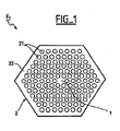
- Figure 1 shows schematically in cross section a photo-crystalline plastic optical fiber obtained by a manufacturing process according to a preferred embodiment of the invention.
- the photocrystalline plastic optical fiber F 1 with a diameter for example between 100 and 1000 ⁇ m and for example with a hexagonal structure comprises a solid core 1 with a diameter for example between 1 and 100 ⁇ m and a sheath 2 covering this core 1.
- Sheath 2 is formed by a periodic arrangement, hexagonal in this example, of cavities 21 for example substantially circular and of microscopic diameter.
- microscopic diameter is meant a (average) diameter of cavity less than a micrometer, of the order of a micrometer or about ten micrometers. The diameter is for example between 1 and 30 micrometers approximately in this example.
- These hollow cavities are arranged longitudinally in a matrix 22 in a sheath polymer obtained by radiation of the type ultraviolet.
- the distance between two closest cavities is in this example smaller than the radius of the cavity.
- the core material is identical to the sheath polymer for a simplicity of realization.
- the hollow cavities contain any other gas.
- FIGs 2 and 3 schematically show the implementation of the method of manufacturing the photo-crystalline plastic optical fiber F 1 of Figure 1, in the preferred embodiment of the invention.
- the first step in the process involves injecting simultaneously at least one liquid composition A curable by a ultraviolet (UV) radiation and at least one other composition B not reactive to UV radiation responsible for hardening of the composition A and for example liquid, which are injected under pressure in an injection plate 4 so that a flow AB is formed.
- UV ultraviolet
- injection conduits 3 which do not communicate with each other the others are arranged at the upper part of the injection plate 4 by example in the form of a disc and provided with holes 40.
- the latter is arranged in a flow chamber 5, for example made of stainless steel (view in cross section in Figure 2).
- Positive displacement pumps (not shown) associated with each of the conduits 3 make it possible to ensure controlled pressures for liquid compositions A and B, pressures by example of the order of 6 bars.
- composition A is a precursor composition sheath polymer and contains a first reactive solvent of the type monomer and / or a first polymer of acrylic or vinyl type, halogenated or non-halogenated.
- This first composition A presents preferably an intrinsic attenuation of less than 5 dB / m.
- composition A is also the precursor composition of the core polymer.
- Liquid composition B contains a compound chosen from non-reactive solvents such as xylenol, fluorinated solvents such as FC-77, butylene glycol, propylene glycol, cyclohexanone, among the oils silicone and among biodegradable polymers such as polymers cellulose.
- Composition B may preferably contain a mixture a non-reactive solvent such as those set out above, and a polymer biodegradable, in a ratio chosen so as to control the viscosity of the composition.
- the viscosity of composition B is preferably greater than the viscosity of composition A to optimize the formation and the desired profile of the flow AB.
- the viscosity of composition B does not exceed preferably five times the viscosity of composition A.
- the viscosities are chosen from the range 200 mPa.s - 5000 mPa.s at 25 ° C.
- composition B makes it possible to adjust the diameter of the cavities of the fiber F: the lower the viscosity the smaller the diameter of the F fiber cavities is small.
- the flow AB is brought by this zone 51 to the calibrated die 6 which gives the desired order of magnitude to the diameter of the fiber F.
- the die 6 is a removable part which allows to easily change the calibration without having to change rooms 5. Alternatively, it is possible that the die 6 or part of the chamber 5.
- the die 5 has for example a hexagonal structure.
- composition B it is possible to place a thermally insulated device at the level conduits 3 until the desired viscosity for the composition is obtained A and composition B.
- composition A is thus hardened by way to form the sheath polymer: the photo-crystalline plastic optical fiber F is thus produced.
- the distance between the source 7 of UV radiation and the die 6 is choose according to cavity diameters and fiber diameter desired.
- Fiber F cavities contain liquid composition B not hardened.
- composition B is chosen such that its refractive index is lower than the refractive index of the sheath polymer (composition A).
- the optical fiber F 1 is wound on a reel 10.
- the liquid composition B is cured by any other means than UV source 6 of given radiation, for the formation of full cavities.
- composition B is gaseous, and preferably the injection pressure of composition B is greater than the injection pressure of the liquid composition A.
- a hole substantially central to the plate receives, instead of composition A, a third composition C not reactive to said UV, liquid or gas.
- the removal is preferably carried out by heat treatment for example identical to that used to form hollow cavities in particular if composition C is liquid and is substantially identical to the composition B.
- Figure 4 schematically shows a perspective view an injection plate 4 'provided with holes 40' of structure similar to that used in the preferred embodiment of the method according to the invention.
- the precursor composition of said sheath polymer such as composition A, is to be injected into a first series of holes 41 (symbolized in black in Figure 4), for example circular, arranged so that allow the formation of the sheath matrix of a plastic optical fiber photo-crystalline according to the invention,
- composition A for example a precursor of a core polymer, such that composition A is injected into a substantially central hole 42, for example circular, arranged to participate in the formation of a full heart.
- a composition not reactive to said ultraviolet radiation such as liquid composition B or a gaseous composition is to be injected in a second series of holes 43, for example circular, having a substantially periodic distribution, in this hexagonal example.
- Each holes of the second series 43 has as closest neighbors six holes of the first series 41 which together form a hexagon H (shown in dotted line).
- the size and shape of the holes can be identical or distinct.
- the diameter of the plate 4 ′ is for example equal to a few mm and its thickness is for example three to five times the diameter of the holes.
- the diameter of the holes is for example of the order of a hundred microns.
- Each hole in the plate 4 ' is optionally extended by a nozzle.
- a third series of holes of smaller dimension than those of the second series are made in plate 4 'and form a periodic arrangement. These holes receive a liquid or gaseous composition D not reactive to UV radiation and preferably identical to composition B, this in the purpose of forming interstitial cavities in addition to the cavities initially planned which are wider.
- the distance between two adjacent cavities, the shape of the cavities, their diameter, their number and their substantially periodic arrangement are adjustable by modification of the second and / or first series of holes.
- the invention also applies to the manufacture of an optical fiber optically coupled multi-core photo-crystalline plastic.
Landscapes
- Engineering & Computer Science (AREA)
- Physics & Mathematics (AREA)
- Mechanical Engineering (AREA)
- General Physics & Mathematics (AREA)
- Optics & Photonics (AREA)
- General Engineering & Computer Science (AREA)
- Civil Engineering (AREA)
- Structural Engineering (AREA)
- Health & Medical Sciences (AREA)
- Manufacturing & Machinery (AREA)
- Ophthalmology & Optometry (AREA)
- Mining & Mineral Resources (AREA)
- Ocean & Marine Engineering (AREA)
- Environmental & Geological Engineering (AREA)
- Life Sciences & Earth Sciences (AREA)
- General Life Sciences & Earth Sciences (AREA)
- Paleontology (AREA)
- Optical Fibers, Optical Fiber Cores, And Optical Fiber Bundles (AREA)
- Casting Or Compression Moulding Of Plastics Or The Like (AREA)
Applications Claiming Priority (2)
| Application Number | Priority Date | Filing Date | Title |
|---|---|---|---|
| FR0302637 | 2003-03-04 | ||
| FR0302637A FR2852107B1 (fr) | 2003-03-04 | 2003-03-04 | Procede de fabrication d'une fibre optique plastique photo-cristalline |
Publications (1)
| Publication Number | Publication Date |
|---|---|
| EP1455206A1 true EP1455206A1 (de) | 2004-09-08 |
Family
ID=32799629
Family Applications (1)
| Application Number | Title | Priority Date | Filing Date |
|---|---|---|---|
| EP04300098A Withdrawn EP1455206A1 (de) | 2003-03-04 | 2004-02-26 | Verfahren zur Herstellung einer photo-kristallinen Plastikfaser |
Country Status (7)
| Country | Link |
|---|---|
| US (1) | US20040212108A1 (de) |
| EP (1) | EP1455206A1 (de) |
| JP (1) | JP2004272248A (de) |
| KR (1) | KR20040078586A (de) |
| CN (1) | CN1598631A (de) |
| CA (1) | CA2459215A1 (de) |
| FR (1) | FR2852107B1 (de) |
Families Citing this family (3)
| Publication number | Priority date | Publication date | Assignee | Title |
|---|---|---|---|---|
| JP6373626B2 (ja) * | 2014-04-10 | 2018-08-15 | 株式会社ダイセル | 高分子光ファイバーの製造方法及び該方法により製造された高分子光ファイバー |
| WO2017103655A1 (en) * | 2015-12-16 | 2017-06-22 | Prysmian S.P.A. | Optical fibre with enhanced high temperature resistance |
| US11009662B2 (en) * | 2017-09-05 | 2021-05-18 | Facebook Technologies, Llc | Manufacturing a graded index profile for waveguide display applications |
Citations (5)
| Publication number | Priority date | Publication date | Assignee | Title |
|---|---|---|---|---|
| JPS6026913A (ja) * | 1983-07-26 | 1985-02-09 | Yokohama Rubber Co Ltd:The | 光フアイバ−心線およびその製造方法 |
| WO2001069289A2 (en) * | 2000-03-10 | 2001-09-20 | Flow Focusing, Inc. | Methods for producing optical fiber by focusing high viscosity liquid |
| EP1172339A1 (de) * | 2000-07-11 | 2002-01-16 | Lucent Technologies Inc. | Verfahren zum Herstellen einer mikrostrukturierten optischen Faser durch ein Sol-Gel-Verfahren |
| WO2002101422A2 (en) * | 2001-06-13 | 2002-12-19 | Samsung Electronics Co., Ltd. | Method for fabricating optical fiber preform using extrusion die |
| WO2003012500A1 (en) * | 2001-07-27 | 2003-02-13 | Rpo Pty Limited | Materials for polymer optical fibers |
Family Cites Families (2)
| Publication number | Priority date | Publication date | Assignee | Title |
|---|---|---|---|---|
| JPH0395505A (ja) * | 1989-09-08 | 1991-04-19 | Nok Corp | 光ファイバの製造方法 |
| US6116516A (en) * | 1996-05-13 | 2000-09-12 | Universidad De Sevilla | Stabilized capillary microjet and devices and methods for producing same |
-
2003
- 2003-03-04 FR FR0302637A patent/FR2852107B1/fr not_active Expired - Fee Related
-
2004
- 2004-02-26 EP EP04300098A patent/EP1455206A1/de not_active Withdrawn
- 2004-02-26 US US10/788,890 patent/US20040212108A1/en not_active Abandoned
- 2004-02-27 CA CA002459215A patent/CA2459215A1/en not_active Abandoned
- 2004-03-03 JP JP2004059078A patent/JP2004272248A/ja active Pending
- 2004-03-03 KR KR1020040014357A patent/KR20040078586A/ko not_active Withdrawn
- 2004-03-04 CN CNA2004100313214A patent/CN1598631A/zh active Pending
Patent Citations (5)
| Publication number | Priority date | Publication date | Assignee | Title |
|---|---|---|---|---|
| JPS6026913A (ja) * | 1983-07-26 | 1985-02-09 | Yokohama Rubber Co Ltd:The | 光フアイバ−心線およびその製造方法 |
| WO2001069289A2 (en) * | 2000-03-10 | 2001-09-20 | Flow Focusing, Inc. | Methods for producing optical fiber by focusing high viscosity liquid |
| EP1172339A1 (de) * | 2000-07-11 | 2002-01-16 | Lucent Technologies Inc. | Verfahren zum Herstellen einer mikrostrukturierten optischen Faser durch ein Sol-Gel-Verfahren |
| WO2002101422A2 (en) * | 2001-06-13 | 2002-12-19 | Samsung Electronics Co., Ltd. | Method for fabricating optical fiber preform using extrusion die |
| WO2003012500A1 (en) * | 2001-07-27 | 2003-02-13 | Rpo Pty Limited | Materials for polymer optical fibers |
Non-Patent Citations (2)
| Title |
|---|
| CHOI J ET AL: "FABRICATION AND PROPERTIES OF POLYMER PHOTONIC CRYSTAL FIBERS", 27 September 2001, INTERNATIONAL PLASTIC OPTICAL FIBRES CONFERENCE. PROCEEDINGS, XX, XX, PAGE(S) 355-360, XP008012113 * |
| PATENT ABSTRACTS OF JAPAN vol. 009, no. 148 (P - 366) 22 June 1985 (1985-06-22) * |
Also Published As
| Publication number | Publication date |
|---|---|
| CA2459215A1 (en) | 2004-09-04 |
| FR2852107A1 (fr) | 2004-09-10 |
| JP2004272248A (ja) | 2004-09-30 |
| US20040212108A1 (en) | 2004-10-28 |
| KR20040078586A (ko) | 2004-09-10 |
| FR2852107B1 (fr) | 2005-09-02 |
| CN1598631A (zh) | 2005-03-23 |
Similar Documents
| Publication | Publication Date | Title |
|---|---|---|
| EP1482606B1 (de) | Optische Faser für Verstärkung oder Laserstrahlung | |
| EP0703480A1 (de) | Optisches Kabel und Vorrichtug zu seiner Fabrikation | |
| FR2514155A1 (fr) | Fibre optique monomode a faible dispersion | |
| EP1067222A1 (de) | Verfahren zur Herstellung von optischen Plastikfasern mit Indexgradienten | |
| FR3069336A1 (fr) | Fibre optique | |
| JP2004533638A (ja) | 薄壁コアを有するバンドギャップ導波路 | |
| EP0165842B1 (de) | Herstellungsverfahren für einen Vielpunktelichtleitkörper | |
| EP1709715A1 (de) | Multimoden-lichtfaser | |
| EP1210751B1 (de) | Mantelgepumpte optische faser und zugehöriges herstellungsverfahren | |
| FR2728694A1 (fr) | Module pour cables a fibres optiques, procede de fabrication et installation a cet effet | |
| FR2852107A1 (fr) | Procede de fabrication d'une fibre optique plastique photo-cristalline | |
| FR2987905A1 (fr) | Dispositif de conversion du profil spatial transverse d'intensite d'un faisceau lumineux, utilisant de preference une fibre optique microstructuree | |
| EP1735882B1 (de) | Hohle optische faser | |
| EP3938326B1 (de) | Verfahren zur herstellung einer mikrostruktuierten hohlkernglasfaser | |
| EP0718648A1 (de) | Herstellungsverfahren für optischen Mehrfachfaserverteiler und damit hergestellter optischer Verteiler | |
| FR2812728A1 (fr) | Procede de regainage de fibre optique et produit ainsi obtenu | |
| EP0943946A1 (de) | Herstellungsverfahren für ein optisches Mehrfachband und das in mindestens zwei optische Bänder teilbar ist | |
| WO1989002876A1 (fr) | Procede de fabrication de fibre optique avec preforme obtenue par retreint | |
| EP1327898A1 (de) | Glasfaser mit einer komplexen Brechungsindexstruktur in Ringform | |
| EP1416070A1 (de) | Verfahren zur Herstellung von optischen Fasern mit Indexgradienten aus Kunststoff und Vorrichtung zur Erzeugung einer Vorform für dieses Verfahren | |
| EP2548710B1 (de) | Herstellungsverfahren eines mikrorohrs | |
| FR2954526A1 (fr) | Dispositif optique comportant une fibre optique effilee et utilisation d'un tel dispositif pour l'injection d'une onde dans une fibre double gaine et pour l'expansion d'une onde en sortie de fibre. | |
| FR3138531A1 (fr) | Fibre optique comportant un réseau de Bragg | |
| WO2004072707A1 (fr) | Ruban a fibres optiques et procede de fabrication d’un ruban a fibres optiques | |
| EP1657262A2 (de) | Photovernetzbare Verbindung für Kunststoffmaterial für Stufenindex-Glasfaser |
Legal Events
| Date | Code | Title | Description |
|---|---|---|---|
| PUAI | Public reference made under article 153(3) epc to a published international application that has entered the european phase |
Free format text: ORIGINAL CODE: 0009012 |
|
| AK | Designated contracting states |
Kind code of ref document: A1 Designated state(s): AT BE BG CH CY CZ DE DK EE ES FI FR GB GR HU IE IT LI LU MC NL PT RO SE SI SK TR |
|
| AX | Request for extension of the european patent |
Extension state: AL HR LT LV MK |
|
| 17P | Request for examination filed |
Effective date: 20050308 |
|
| AKX | Designation fees paid |
Designated state(s): AT BE BG CH CY CZ DE DK EE ES FI FR GB GR HU IE IT LI LU MC NL PT RO SE SI SK TR |
|
| 17Q | First examination report despatched |
Effective date: 20050512 |
|
| RIC1 | Information provided on ipc code assigned before grant |
Ipc: B29D 11/00 20060101ALI20060425BHEP Ipc: G02B 6/02 20060101AFI20060425BHEP |
|
| GRAP | Despatch of communication of intention to grant a patent |
Free format text: ORIGINAL CODE: EPIDOSNIGR1 |
|
| GRAS | Grant fee paid |
Free format text: ORIGINAL CODE: EPIDOSNIGR3 |
|
| STAA | Information on the status of an ep patent application or granted ep patent |
Free format text: STATUS: THE APPLICATION IS DEEMED TO BE WITHDRAWN |
|
| 18D | Application deemed to be withdrawn |
Effective date: 20070328 |