EP1455251B1 - Commutateur de sécurité configurable - Google Patents
Commutateur de sécurité configurable Download PDFInfo
- Publication number
- EP1455251B1 EP1455251B1 EP04004164A EP04004164A EP1455251B1 EP 1455251 B1 EP1455251 B1 EP 1455251B1 EP 04004164 A EP04004164 A EP 04004164A EP 04004164 A EP04004164 A EP 04004164A EP 1455251 B1 EP1455251 B1 EP 1455251B1
- Authority
- EP
- European Patent Office
- Prior art keywords
- configuration
- option
- safety
- monitoring unit
- maximum
- Prior art date
- Legal status (The legal status is an assumption and is not a legal conclusion. Google has not performed a legal analysis and makes no representation as to the accuracy of the status listed.)
- Expired - Lifetime
Links
Images

Classifications
-
- G—PHYSICS
- G05—CONTROLLING; REGULATING
- G05B—CONTROL OR REGULATING SYSTEMS IN GENERAL; FUNCTIONAL ELEMENTS OF SUCH SYSTEMS; MONITORING OR TESTING ARRANGEMENTS FOR SUCH SYSTEMS OR ELEMENTS
- G05B23/00—Testing or monitoring of control systems or parts thereof
- G05B23/02—Electric testing or monitoring
- G05B23/0205—Electric testing or monitoring by means of a monitoring system capable of detecting and responding to faults
- G05B23/0259—Electric testing or monitoring by means of a monitoring system capable of detecting and responding to faults characterized by the response to fault detection
- G05B23/0286—Modifications to the monitored process, e.g. stopping operation or adapting control
-
- G—PHYSICS
- G05—CONTROLLING; REGULATING
- G05B—CONTROL OR REGULATING SYSTEMS IN GENERAL; FUNCTIONAL ELEMENTS OF SUCH SYSTEMS; MONITORING OR TESTING ARRANGEMENTS FOR SUCH SYSTEMS OR ELEMENTS
- G05B19/00—Program-control systems
- G05B19/02—Program-control systems electric
- G05B19/04—Program control other than numerical control, i.e. in sequence controllers or logic controllers
- G05B19/042—Program control other than numerical control, i.e. in sequence controllers or logic controllers using digital processors
- G05B19/0428—Safety, monitoring
-
- G—PHYSICS
- G05—CONTROLLING; REGULATING
- G05B—CONTROL OR REGULATING SYSTEMS IN GENERAL; FUNCTIONAL ELEMENTS OF SUCH SYSTEMS; MONITORING OR TESTING ARRANGEMENTS FOR SUCH SYSTEMS OR ELEMENTS
- G05B9/00—Safety arrangements
- G05B9/02—Safety arrangements electric
-
- G—PHYSICS
- G05—CONTROLLING; REGULATING
- G05B—CONTROL OR REGULATING SYSTEMS IN GENERAL; FUNCTIONAL ELEMENTS OF SUCH SYSTEMS; MONITORING OR TESTING ARRANGEMENTS FOR SUCH SYSTEMS OR ELEMENTS
- G05B2219/00—Program-control systems
- G05B2219/30—Nc systems
- G05B2219/31—From computer integrated manufacturing till monitoring
- G05B2219/31154—Actuator sensor bus, asi, intelligent actuator, motor, sensor
Definitions
- the invention relates to a method according to the preamble of claim 1.
- Such methods are generally used to control safety-related processes of implements such as machinery and equipment by means of a control system.
- the implements are activated and deactivated depending on the switch states of safety components.
- the safety components can be formed by optical sensors, such as light barriers and light grids, which monitor the apron of such a working device.
- the safety components of emergency stop switches and the like may be formed. With these, the implement can be manually put out of order to avoid dangerous conditions.
- the activation and deactivation of the implement is done via a monitor unit, which evaluates the switching states of the safety components.
- the control system may in particular be formed by a bus system.
- a bus system is from the DE 198 15 147 A1 known. This is a bus system designed according to the master-slave system.
- the required level of security is formed by a monitor unit formed by a redundant evaluation unit, which listens to the signals transmitted via the bus system for determining the switching states of the safety components.
- An automation system which comprises a bus system, I / O bus users connected thereto and a standard control device, and at least one safety analyzer, which overhears the data flow via the bus system and is designed to execute at least one safety-related function.
- the standard control device controls at least one safety-related output.
- the safety analyzer is set up to check and / or process safety-related data in the bus data stream.
- the invention has for its object to provide a method of the type mentioned, which can be changed and expanded with the least possible effort, without its safety function is impaired.
- the method according to the invention serves to control safety-related processes of at least one working device by means of a control system with at least one monitoring unit, by means of which the working device can be activated or deactivated depending on switching states of safety components, the maximum number of connectable safety components forming a maximum configuration.
- a commissioning module can be connected to the monitor unit.
- an option list is stored with a number of options, each option forming an extension of a basic configuration within the maximum configuration defined by a subset of the maximum configuration.
- an option from the option list for generating a current configuration for the operation of the control system is selectable, wherein the validity of the configuration is checked in the monitor unit.
- the basic idea of the invention is that the designer, who designs the control system with the safety-critical part of the monitor unit, stores all safety components that can be connected to the control system as a maximum configuration in the monitor unit. Furthermore, the base configuration of the control system is stored by the designer in the monitor unit, which forms the simplest embodiment of a possible configuration of security components connected to the control system. Furthermore, by the designer in the form of option lists in the Monitor Unit Options which contain variations, in particular extensions with regard to the basic configuration. In one option, security components can be added or removed to the security components of the basic configuration.
- the commissioning or service technician after preferably the maximum configuration and the option list was read by the monitor unit in the commissioning module, the respective option, which is adapted to the desired retrofitting of the implements, in the commissioning module.
- a download procedure for implementing the configuration of the security components corresponding to the option in the monitor unit is generated by the commissioning engineer or the service technician after entering the option in the monitor unit.
- a machine configuration file is automatically generated in the monitor unit, which corresponds to the current circuit diagram with the security component connected according to the selected option.
- the monitor unit outputs the machine configuration file and an option file with the selected option as a result of the download procedure performed.
- the commissioning engineer or service technician can make the decision about the release of the changed configuration of the safety components solely by checking the option list. A review of the entire circuit diagram, that is, the machine configuration file is not required for this purpose. Rather, the machine configuration file is output by the monitor unit solely for documentation purposes.
- the manual effort for changing the configuration of the control system is thus kept extremely low, since only the respective option has to be entered by the commissioning engineer or service technician in the commissioning module and manually checked at the end of the configuration process.
- the change in the circuit diagram of the control system made on the basis of the entered option and, associated therewith, the change of the scope of the backup function of the monitor unit are automatically performed in the monitor unit on the basis of the data stored there, namely the maximum configuration, basic configuration and option list.
- the error safety in the change of the control system is considerably increased.
- the maximum configuration need not be stored in the monitor unit.
- the commissioning engineer selects an option with the commissioning module.
- the corresponding configuration for operating the control system together with a check digit is then generated in the monitor unit.
- the validity of the configuration can be checked automatically in the control system or, in the simplest case, manually by an operator in which the check digit is compared with a setpoint.
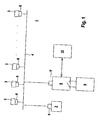
- FIG. 1 shows an exemplary embodiment of a control system 1 for controlling safety-relevant processes.
- the control system 1 is formed in the present case by a bus system which operates according to the master-slave principle.
- the bus system has a master, which is integrated, for example, in a PLC controller 2.
- Slaves forming safety components 3 are connected via bus lines 4 to the master.
- the master polls the individual slaves cyclically under predetermined addresses, whereupon each slave sends a response to the master.
- the bus system is formed by the ASi bus system.
- the ASi bus system is especially designed for the connection of binary sensors and actuators.
- the functioning of the ASi bus system is in " ASI - The Actuator Sensor Interface for Automation ", Werner Kriesel, Otto W. Madelung, Carl Hanser Verlag, 1994 whose content is included in the disclosure of this application.
- the data transmitted via the bus system are Manchester-coded and are transmitted as alternating, sin 2- shaped voltage pulses via the bus lines 4.
- the master is followed by an analog circuit 5, which has a respective not-shown transmitting element and a receiving element.
- the binary data of a master call is converted into a sequence of sin 2- shaped voltage pulses. These signals are sent via the bus lines 4 to the slaves.
- the signals sent from the slaves to the master via the bus lines 4 are converted into binary data sequences in the receiving element.
- Each slave is assigned an interface module 6, which in the present example is formed by an ASi-IC.
- the interface module 6 the sequences of sin 2- shaped voltage pulses received via the bus line 4 are converted into binary data.
- the slave response in the form of binary data is converted into a sequence of sin 2- shaped voltage pulses and sent via the bus lines 4 to the master.
- the operation of a working device 7 is controlled as a safety-relevant process.
- the working device 7 is activated or deactivated as a function of the signals generated by the safety components 3.
- the safety components 3 are preferably binary switching safety switches whose switching states are used to control the working device 7.
- Such safety switches can be formed by optical sensors, such as light barriers, by means of which the penetration of objects into a danger zone can be monitored.
- a monitor unit 8 which consists essentially of a redundantly constructed computer unit.
- the monitor unit 8 is connected via a further analog circuit 5 'to the bus system.
- the monitor unit 8 forms neither a master nor a slave, but represents a purely passive bus subscriber, which continuously listens to the signals transmitted via the bus lines 4.
- the switching states of the safety components 3 are thereby read into the monitor unit 8.
- a switching signal is generated in the monitor unit 8, which is output for activating or deactivating the implement 7 via a safe switching output 9.
- the arrangement according to FIG. 1 comprises a working device 7 and a monitor unit 8.
- the bus system can generally be extended in such a way that several working devices 7 and several monitoring units 8 are connected to it.
- a commissioning module 10 can be connected to the monitor unit 8.
- the commissioning module 10 is formed, for example, by a personal computer.
- Such a new configuration of the bus system is necessary, for example, when the implement 7 is rebuilt or expanded, so that the number and arrangement of the security components 3 for monitoring the implement 7 must be changed.
- the implement 7 consists of a machine 7a.
- four safety components 32-35 are provided.
- the first safety components 32, 33 mechanically actuated emergency stop switch are provided by means of which the machine 7a manually disabled in case of danger can be.
- the rear side of the machine 7a is monitored by means of a first light grid as further safety component 34.
- the front side of the machine 7a is monitored by means of a second light grid as further safety component 35.
- the basic version of the implement 7 can be expanded by installing a conveyor belt 7b in front of the machine 7a.
- the light grid 35 for hazard area monitoring is no longer needed and is therefore removed from the machine 7a.
- a further emergency stop switch is required as an additional security component 37.
- This function is performed by a commissioning engineer, who takes the system according to Figure 1 into operation, or a service technician, who is authorized to rebuild the implement 7, by means of the commissioning module 10.
- the configuration of the components of the bus system is triggered by the commissioning modules 10 and automatically in the monitor unit 8, that is carried out automatically.
- a maximum configuration is stored in the monitor unit 8, which contains a list of all security components 3, which can be assigned to the implement 7 in all its possible variations and stages.
- monitor unit 8 which defines the security components 3, which are assigned to the implement 7 in its basic version.
- an option list with options is stored in the monitor unit 8.
- the individual options define the safety components 3, which are assigned to the implements 7 in its various variants and configuration levels. It is essential that the option list options cover all possible variants and development levels.
- the maximum configuration contains all the safety components 3 that can be assigned to the implement 7 to ensure safety functions.
- the basic configuration and the options list define all connection combinations of the safety components 3 for the different variants and configuration levels of the implement 7 and thus contain all possible circuit diagram variants of the overall system. These data are stored in the monitor unit 8 as a database by the designer who designs the safety-relevant system.
- the commissioning engineer or service technician selects the desired option via the commissioning module 10.
- the maximum configuration, the basic configuration and the option list are preferably read from the monitor unit 8 into the commissioning module 10.
- the selected option is implemented in the monitor unit 8 and the associated circuit diagram is automatically generated as a machine configuration file. It is essential here that the validity of the configuration selected in the commissioning module 10 is checked in the monitor unit 8, with only one validly selected configuration being implemented in the monitor unit 8.
- the option entered in the commissioning module 10 in the monitor unit 8 is compared with the option list options there for checking the validity of the current configuration.
- the machine configuration file generated by the download procedure which corresponds to the schema of the changed asset including the option, is output for documentation purposes.
- an option file is output which documents the option implemented in the monitor unit 8 and selected by means of the commissioning module 10.
- the commissioning engineer or service technician In order to release the configuration of the safety components 3 generated in the monitor unit 8, the commissioning engineer or service technician only needs to check the options file, but not the entire circuit diagram automatically generated in the monitor unit 8 in the form of the machine configuration file.
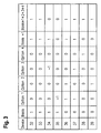
- the maximum configuration of a system according to FIG. 2 comprises a total of eight safety components 3, which are designated in FIG. 3 by the reference numerals 32-39.
- the maximum configuration defines the maximum number of security components 3 that can be assigned to the system according to FIG. 2 in its possible variants and expansion stages.
- the Basic configuration in the column "base" of Figure 3 defines the basic version, in which alone the machine 7a of Figure 2 forms the implement 7.
- the basic configuration is formed as a basic value sequence of binary values 0 and 1, which are assigned to the individual safety components 32-39 of the maximum configuration. Since the emergency-stop switches 32, 33 and light grids are assigned to the implement 7 (FIG. 2a) formed by the machine 7a in the basic version, but not the safety components 36-39, the elements of the basic value sequence assigned to the safety components 32-35 respectively the value 1. By contrast, the elements of the basic value sequence assigned to the safety components 36 - 39 each have the value 0.
- the options 1 - 4 in FIG. 3 define different expansion stages of the basic version of the implement 7 according to FIG. 2.
- Option 1 defines the expansion stage according to FIG. 2, according to which the machine 7a is expanded with the upstream conveyor belt 7b.
- Option 2 defines an extension in which, in addition to the machine 7a, a loading / unloading vehicle is provided.
- Option 3 defines an extension in which a bearing interface is provided in addition to the machine 7a.
- Option 4 defines an extension in which a loading unit is provided in addition to the machine 7a.
- the columns option 1 to option 4 each form an option value sequence whose elements have the values -1, 0 and +1. Each of these elements is associated with an element of the base value sequence.
- the commissioning engineer or the service technician also arranges the safety components 32 - 37 on the implement 7 changed. While the safety components 32-34 formed by the light grid and the emergency stop switches remain on the machine 7a, the safety component 35 formed by the light grid on the front side of the machine 7a is removed and, in addition, the safety components 36, 37 are monitored to monitor the conveyor belt 7b the implement 7 mounted.
- Table 1 option text activated disabled 1 conveyor belt X 2 Loading / unloading X 3 Storage Interface X 4 Loading unit X
- the commissioning engineer will be shown the available options with a corresponding text. Furthermore, the current status is displayed that none of the options is activated, that is, the implement 7 is realized in the basic version.
- the commissioning needs only to select the option 1, that is, the commissioning must only know that the implement 7 is extended with a conveyor belt 7b and note this in the menu according to Table 1 accordingly.
- the commissioning engineer only needs to set option 1 from deactivated to activated. Thereafter, the selected option 1 is loaded into the monitor unit 8 and, starting from the commissioning module 10, a download procedure for implementing option 1 is started in the monitor unit 8.
- option 1 is activated according to FIG. 3, whereby the basic configuration is modified accordingly.
- the option value string of option 1 contains the values -1, 0, +1. With the value - 1 the assigned element of the base value sequence is changed to the value 0. A value of +1 changes the associated element of the base value sequence to 1. A value of 0 leaves the value of the associated element of the base value sequence unchanged.
- the result of this change of the basic configuration is shown in the column "Base +1" in FIG. This column thus contains the configuration of the safety components 3 for the basic configuration extended with option 1.
- the basic configuration changed according to option 1 leads to the configuration of security components 3 according to the column "base + 1" which corresponds to the arrangement of the security components 3, ie the security components 32-34 and 36, 37 are for monitoring the implement 7 according to FIG. 2b intended.
- This configuration is generated automatically in the monitor unit 8.
- the commissioning engineer could also select the options 2 - 4, so that then according to the columns “Option 2" to “Option 4" in FIG 3 the base configuration is changed accordingly.
- the column “Base + 1 + 2 + 3 + 4" in Figure 3 shows the configuration of the safety components 3 when all options 1 - 4 are selected.
- the machine configuration file with the valid circuit diagram of the control system 1, in particular with the arrangement of the safety components 3 in accordance with the "base +1" column in FIG. 3, is output for the commissioning person for documentation purposes.
- the commissioning engineer receives as an acknowledgment of the configuration carried out by him an options file, which occupies the option selection performed.
- the options file essentially has the content according to Table 2.
- Table 2 option text active 1 conveyor belt Yes 2 Loading / unloading No 3 Storage Interface No 4 Loading unit No
- the commissioning engineer only has to check this option file for the release of the control system 1 in the changed configuration, but not the entire circuit diagram of the arrangement.
Landscapes
- Physics & Mathematics (AREA)
- General Physics & Mathematics (AREA)
- Engineering & Computer Science (AREA)
- Automation & Control Theory (AREA)
- Programmable Controllers (AREA)
- Alarm Systems (AREA)
- Air Bags (AREA)
- Filters And Equalizers (AREA)
- Percussion Or Vibration Massage (AREA)
- Testing And Monitoring For Control Systems (AREA)
Claims (18)
- Procédé pour commander des processus de sécurité d'au moins un appareil de travail au moyen d'un système de commande, lequel comporte au moins une unité de contrôle au moyen de laquelle l'appareil de travail est activé ou désactivé en fonction d'états de commutation de composants de sécurité, caractérisé en ce qu'un module de mise en service (10) peut être connecté à l'unité de contrôle (8), que le nombre maximal de composants de sécurité (3) connectables forme une configuration maximale, qu'une liste d'options avec un nombre d'options est enregistrée dans l'unité de contrôle (8) et/ou le module de mise en service, chaque option formant, dans les limites de la configuration maximale, une extension d'une configuration de base qui est définie par un sous-ensemble de la configuration maximale et qu'il est possible de sélectionner dans le module de mise en service une option de la liste d'options pour générer une configuration actuelle pour le fonctionnement du système de commande (1), la validité de la configuration étant vérifiée dans l'unité de contrôle (8).
- Procédé selon la revendication 1, caractérisé en ce que pour vérifier la validité d'une configuration sélectionnée, on lui associe un chiffre de contrôle qui est comparé avec une valeur de consigne dans l'unité de contrôle (8) et/ou par un(e) opérateur/trice.
- Procédé selon la revendication 1, caractérisé en ce que la configuration maximale est enregistrée dans l'unité de contrôle.
- Procédé selon la revendication 3, caractérisé en ce que pour vérifier la validité d'une configuration sélectionnée, celle-ci est comparée dans l'unité de contrôle (8) avec les options de la liste d'options.
- Procédé selon l'une des revendications 1 à 4, caractérisé en ce que le système de commande est formé par un système de bus fonctionnant selon le principe maître-esclave.
- Procédé selon l'une des revendications 1 à 5, caractérisé en ce que les composants de sécurité (3) forment des esclaves du système de bus.
- Procédé selon l'une des revendications 1 à 6, caractérisé en ce que les composants de sécurité (3) sont formés de barrières lumineuses, de rideaux lumineux et/ou d'interrupteurs d'arrêt d'urgence.
- Procédé selon l'une des revendications 1 à 7, caractérisé en ce que l'unité de contrôle (8) est formée d'une unité informatique redondante.
- Procédé selon la revendication 8, caractérisé en ce que l'unité de contrôle (8) écoute les signaux transmis sur le système de bus pour déterminer les états de commutation des composants de sécurité (3).
- Procédé selon l'une des revendications 1 à 9, caractérisé en ce que le module de mise en service (10) est formé d'un ordinateur personnel.
- Procédé selon l'une des revendications 1 à 10, caractérisé en ce que pour effectuer une mise en service, la configuration maximale et la liste d'options sont chargées dans le module de mise en service (10).
- Procédé selon l'une des revendications 1 à 11, caractérisé en ce qu'après la sélection d'une option dans le module de mise en service (10), une procédure de téléchargement est démarrée dans l'unité de contrôle (8), au moyen de laquelle la configuration de composants de sécurité (3) correspondant à l'option est implémentée.
- Procédé selon la revendication 11, caractérisé en ce qu'un fichier de configuration de machine est généré dans l'unité de contrôle (8) avec la procédure de téléchargement.
- Procédé selon l'une des revendications 12 ou 13, caractérisé en ce qu'après que la procédure de téléchargement a eu lieu, un fichier d'option avec l'option sélectionnée est délivré par l'unité de contrôle (8) en vue de sa vérification et de sa validation.
- Procédé selon l'une des revendications 12 à 14, caractérisé en ce qu'après que la procédure de téléchargement a eu lieu, le fichier de configuration de machine peut être délivré par l'unité de contrôle (8).
- Procédé selon l'une des revendications 1 à 15, caractérisé en ce que la configuration maximale est formée d'une liste des composants de sécurité (3) connectables au maximum.
- Procédé selon la revendication 16, caractérisé en ce que la configuration de base est formée d'une suite de valeurs de base associée à la configuration maximale dont les éléments prennent des valeurs binaires 0 ou 1, sachant que si la valeur 0 d'un élément est affectée à un composant de sécurité (3) de la configuration maximale celui-ci est inactif et que si la valeur 1 d'un élément est affectée à un composant de sécurité (3) de la configuration maximale celui-ci est actif.
- Procédé selon la revendication 17, caractérisé en ce que chaque option est formée d'une suite de valeurs d'option de valeurs -1, 0, +1 associée à la configuration de base, sachant qu'avec la valeur 0 une valeur définie dans la configuration de base est prise en compte, qu'avec la valeur +1 un composant de sécurité (3) défini comme actif ou inactif dans la configuration de base est inclus dans l'option en tant que composant de sécurité (3) activé, et qu'avec la valeur -1 un composant de sécurité (3) défini comme actif ou inactif dans la configuration de base est inclus dans l'option en tant que composant de sécurité (3) inactivé.
Applications Claiming Priority (2)
| Application Number | Priority Date | Filing Date | Title |
|---|---|---|---|
| DE10309098A DE10309098A1 (de) | 2003-03-03 | 2003-03-03 | Steuerung zur Steuerung sicherheitsrelevanter Prozesse |
| DE10309098 | 2003-03-03 |
Publications (2)
| Publication Number | Publication Date |
|---|---|
| EP1455251A1 EP1455251A1 (fr) | 2004-09-08 |
| EP1455251B1 true EP1455251B1 (fr) | 2008-01-02 |
Family
ID=32797784
Family Applications (1)
| Application Number | Title | Priority Date | Filing Date |
|---|---|---|---|
| EP04004164A Expired - Lifetime EP1455251B1 (fr) | 2003-03-03 | 2004-02-25 | Commutateur de sécurité configurable |
Country Status (4)
| Country | Link |
|---|---|
| EP (1) | EP1455251B1 (fr) |
| AT (1) | ATE382886T1 (fr) |
| DE (2) | DE10309098A1 (fr) |
| ES (1) | ES2297287T3 (fr) |
Cited By (1)
| Publication number | Priority date | Publication date | Assignee | Title |
|---|---|---|---|---|
| DE102007053078A1 (de) * | 2007-09-14 | 2009-03-19 | ICP DAS Co., Ltd., Hu-Kou | Dezentralisiertes Automatisierungssystem und eine darin eingesetzte I/O-Erweiterungseinheit |
Families Citing this family (3)
| Publication number | Priority date | Publication date | Assignee | Title |
|---|---|---|---|---|
| DE102009030159B4 (de) * | 2009-06-24 | 2012-04-19 | Langmatz Gmbh | Anforderungsgerät für eine Verkehrsampel |
| EP2375636A1 (fr) * | 2010-03-29 | 2011-10-12 | Sick Ag | Dispositif et procédé de configuration d'un système de bus |
| DE102020111450A1 (de) | 2020-04-27 | 2021-10-28 | Bayerische Motoren Werke Aktiengesellschaft | Erkennen von Fehlern in einem Computernetzwerk |
Family Cites Families (4)
| Publication number | Priority date | Publication date | Assignee | Title |
|---|---|---|---|---|
| DE4240071A1 (de) * | 1992-11-28 | 1994-06-01 | Square D Deutschland | Schaltungsanordnung zur elektrischen Sicherheitsüberwachung von Schalteinrichtungen |
| DE19707241C2 (de) * | 1997-02-25 | 2000-05-31 | Pilz Gmbh & Co | Modulares Sicherheitsschaltgerät |
| DE19927635B4 (de) * | 1999-06-17 | 2009-10-15 | Phoenix Contact Gmbh & Co. Kg | Sicherheitsbezogenes Automatisierungsbussystem |
| DE10024316B4 (de) * | 2000-05-17 | 2004-02-05 | Dirar Najib | Anpassbares Sicherheitsüberwachungsgerät |
-
2003
- 2003-03-03 DE DE10309098A patent/DE10309098A1/de not_active Withdrawn
-
2004
- 2004-02-25 AT AT04004164T patent/ATE382886T1/de active
- 2004-02-25 EP EP04004164A patent/EP1455251B1/fr not_active Expired - Lifetime
- 2004-02-25 DE DE502004005799T patent/DE502004005799D1/de not_active Expired - Lifetime
- 2004-02-25 ES ES04004164T patent/ES2297287T3/es not_active Expired - Lifetime
Cited By (1)
| Publication number | Priority date | Publication date | Assignee | Title |
|---|---|---|---|---|
| DE102007053078A1 (de) * | 2007-09-14 | 2009-03-19 | ICP DAS Co., Ltd., Hu-Kou | Dezentralisiertes Automatisierungssystem und eine darin eingesetzte I/O-Erweiterungseinheit |
Also Published As
| Publication number | Publication date |
|---|---|
| DE10309098A1 (de) | 2004-09-16 |
| ATE382886T1 (de) | 2008-01-15 |
| ES2297287T3 (es) | 2008-05-01 |
| DE502004005799D1 (de) | 2008-02-14 |
| EP1455251A1 (fr) | 2004-09-08 |
Similar Documents
| Publication | Publication Date | Title |
|---|---|---|
| EP2315088B1 (fr) | Commande de sécurité | |
| EP2363770B1 (fr) | Dispositif de sécurité doté d'un contrôleur configurable | |
| EP0742499A2 (fr) | Traitement fiable de signaux orientés sûreté | |
| EP1362269A2 (fr) | Procede et dispositif de programmation d'une commande de securite | |
| DE102020122870A1 (de) | Verfahren zur Konfiguration einer modularen Sicherheitsschaltvorrichtung | |
| EP2356527A2 (fr) | Commande de sécurité et procédé pour commander une installation automatisée comprenant une pluralité de composants matériels | |
| EP2246756B1 (fr) | Procédé et appareil de commande destinés à commander un composant d'automatisation industriel lié à la sécurité | |
| EP0886823B1 (fr) | Procede pour controler le fonctionnement d'une unite de calcul | |
| EP2098928A1 (fr) | Procédé et dispositif adaptés à la programmation et/ou la configuration d'un contrôleur de sécurité | |
| WO2008014940A1 (fr) | Dispositif de commande et procédé pour la commande de fonctions | |
| EP1455251B1 (fr) | Commutateur de sécurité configurable | |
| BE1026448B1 (de) | Verfahren und Vorrichtung zur Konfiguration einer Hardwarekomponente | |
| EP1128241B1 (fr) | Procédé et dispositif de surveillance d' un dispositif de commande | |
| DE102008045590B3 (de) | Bussystem | |
| DE69010818T2 (de) | Verfahren zur Anpassung eines Regelsystems für eine Heizanlage mit einem Brenner und ein Regelsystem für solch eine Anlage. | |
| EP1920299B1 (fr) | Procede et dispositif pour surveiller un dispositif technique | |
| EP1353246B1 (fr) | Dispositif de commutation de sécurité | |
| EP1327922B1 (fr) | Arrangement avec un interrupteur de sécurité | |
| EP1248168A2 (fr) | Appareil et procédé pour obtenir des informations de diagnostic | |
| EP2013731B1 (fr) | Agencement de circuit et procédé permettant de faire fonctionner un agencement de circuit | |
| WO2005001692A2 (fr) | Procede et dispositif pour la surveillance d'un systeme reparti | |
| EP2312408B1 (fr) | Commande de sécurité modulaire | |
| EP1179428B1 (fr) | Procédé et dispositif pour exécuter des pas d'un procédé | |
| DE102018103965A1 (de) | Verfahren zur Mensch-Maschine-Kommunikation mittels einer Mensch-Maschine-Schnittstelle und Vorrichtung hierfür | |
| EP1998240B1 (fr) | Commande fonctionnant de manière cyclique et procédé destiné à intégrer des modules logiciels dans le processus de fonctionnement d'une commande |
Legal Events
| Date | Code | Title | Description |
|---|---|---|---|
| PUAI | Public reference made under article 153(3) epc to a published international application that has entered the european phase |
Free format text: ORIGINAL CODE: 0009012 |
|
| 17P | Request for examination filed |
Effective date: 20040611 |
|
| AK | Designated contracting states |
Kind code of ref document: A1 Designated state(s): AT BE CH DE ES FR GB IT LI |
|
| AX | Request for extension of the european patent |
Extension state: AL LT LV MK |
|
| AKX | Designation fees paid |
Designated state(s): AT BE CH DE ES FR GB IT LI |
|
| GRAP | Despatch of communication of intention to grant a patent |
Free format text: ORIGINAL CODE: EPIDOSNIGR1 |
|
| GRAS | Grant fee paid |
Free format text: ORIGINAL CODE: EPIDOSNIGR3 |
|
| GRAA | (expected) grant |
Free format text: ORIGINAL CODE: 0009210 |
|
| AK | Designated contracting states |
Kind code of ref document: B1 Designated state(s): AT BE CH DE ES FR GB IT LI |
|
| REG | Reference to a national code |
Ref country code: GB Ref legal event code: FG4D Free format text: NOT ENGLISH |
|
| GBT | Gb: translation of ep patent filed (gb section 77(6)(a)/1977) |
Effective date: 20080103 |
|
| REG | Reference to a national code |
Ref country code: CH Ref legal event code: EP Ref country code: CH Ref legal event code: NV Representative=s name: ROTTMANN, ZIMMERMANN + PARTNER AG |
|
| REF | Corresponds to: |
Ref document number: 502004005799 Country of ref document: DE Date of ref document: 20080214 Kind code of ref document: P |
|
| REG | Reference to a national code |
Ref country code: ES Ref legal event code: FG2A Ref document number: 2297287 Country of ref document: ES Kind code of ref document: T3 |
|
| ET | Fr: translation filed | ||
| PLBE | No opposition filed within time limit |
Free format text: ORIGINAL CODE: 0009261 |
|
| STAA | Information on the status of an ep patent application or granted ep patent |
Free format text: STATUS: NO OPPOSITION FILED WITHIN TIME LIMIT |
|
| 26N | No opposition filed |
Effective date: 20081003 |
|
| REG | Reference to a national code |
Ref country code: CH Ref legal event code: PFA Owner name: LEUZE ELECTRONIC GMBH + CO KG Free format text: LEUZE ELECTRONIC GMBH + CO KG#IN DER BRAIKE 1#73277 OWEN/TECK (DE) -TRANSFER TO- LEUZE ELECTRONIC GMBH + CO KG#IN DER BRAIKE 1#73277 OWEN/TECK (DE) |
|
| PGFP | Annual fee paid to national office [announced via postgrant information from national office to epo] |
Ref country code: AT Payment date: 20140212 Year of fee payment: 11 Ref country code: ES Payment date: 20140226 Year of fee payment: 11 Ref country code: BE Payment date: 20140218 Year of fee payment: 11 |
|
| PGFP | Annual fee paid to national office [announced via postgrant information from national office to epo] |
Ref country code: GB Payment date: 20140218 Year of fee payment: 11 |
|
| REG | Reference to a national code |
Ref country code: FR Ref legal event code: PLFP Year of fee payment: 12 |
|
| PGFP | Annual fee paid to national office [announced via postgrant information from national office to epo] |
Ref country code: FR Payment date: 20150219 Year of fee payment: 12 |
|
| PG25 | Lapsed in a contracting state [announced via postgrant information from national office to epo] |
Ref country code: BE Free format text: LAPSE BECAUSE OF NON-PAYMENT OF DUE FEES Effective date: 20150228 |
|
| REG | Reference to a national code |
Ref country code: AT Ref legal event code: MM01 Ref document number: 382886 Country of ref document: AT Kind code of ref document: T Effective date: 20150225 |
|
| GBPC | Gb: european patent ceased through non-payment of renewal fee |
Effective date: 20150225 |
|
| PG25 | Lapsed in a contracting state [announced via postgrant information from national office to epo] |
Ref country code: AT Free format text: LAPSE BECAUSE OF NON-PAYMENT OF DUE FEES Effective date: 20150225 |
|
| PG25 | Lapsed in a contracting state [announced via postgrant information from national office to epo] |
Ref country code: GB Free format text: LAPSE BECAUSE OF NON-PAYMENT OF DUE FEES Effective date: 20150225 |
|
| REG | Reference to a national code |
Ref country code: ES Ref legal event code: FD2A Effective date: 20160906 |
|
| REG | Reference to a national code |
Ref country code: CH Ref legal event code: PCAR Free format text: NEW ADDRESS: GARTENSTRASSE 28 A, 5400 BADEN (CH) |
|
| REG | Reference to a national code |
Ref country code: FR Ref legal event code: ST Effective date: 20161028 |
|
| PG25 | Lapsed in a contracting state [announced via postgrant information from national office to epo] |
Ref country code: ES Free format text: LAPSE BECAUSE OF NON-PAYMENT OF DUE FEES Effective date: 20150226 |
|
| PG25 | Lapsed in a contracting state [announced via postgrant information from national office to epo] |
Ref country code: FR Free format text: LAPSE BECAUSE OF NON-PAYMENT OF DUE FEES Effective date: 20160229 |
|
| PGFP | Annual fee paid to national office [announced via postgrant information from national office to epo] |
Ref country code: DE Payment date: 20190206 Year of fee payment: 16 |
|
| PGFP | Annual fee paid to national office [announced via postgrant information from national office to epo] |
Ref country code: IT Payment date: 20200225 Year of fee payment: 17 |
|
| PGFP | Annual fee paid to national office [announced via postgrant information from national office to epo] |
Ref country code: CH Payment date: 20200219 Year of fee payment: 17 |
|
| REG | Reference to a national code |
Ref country code: DE Ref legal event code: R119 Ref document number: 502004005799 Country of ref document: DE |
|
| PG25 | Lapsed in a contracting state [announced via postgrant information from national office to epo] |
Ref country code: DE Free format text: LAPSE BECAUSE OF NON-PAYMENT OF DUE FEES Effective date: 20200901 |
|
| PG25 | Lapsed in a contracting state [announced via postgrant information from national office to epo] |
Ref country code: LI Free format text: LAPSE BECAUSE OF NON-PAYMENT OF DUE FEES Effective date: 20210228 Ref country code: CH Free format text: LAPSE BECAUSE OF NON-PAYMENT OF DUE FEES Effective date: 20210228 |
|
| PG25 | Lapsed in a contracting state [announced via postgrant information from national office to epo] |
Ref country code: IT Free format text: LAPSE BECAUSE OF NON-PAYMENT OF DUE FEES Effective date: 20210225 |