EP1455365A2 - Reflektives Röntgenmikroskop und Inspektionssystem zur Untersuchung von Objekten mit Wellenlängen 100nm - Google Patents
Reflektives Röntgenmikroskop und Inspektionssystem zur Untersuchung von Objekten mit Wellenlängen 100nm Download PDFInfo
- Publication number
- EP1455365A2 EP1455365A2 EP04013866A EP04013866A EP1455365A2 EP 1455365 A2 EP1455365 A2 EP 1455365A2 EP 04013866 A EP04013866 A EP 04013866A EP 04013866 A EP04013866 A EP 04013866A EP 1455365 A2 EP1455365 A2 EP 1455365A2
- Authority
- EP
- European Patent Office
- Prior art keywords
- inspection system
- plane
- mirror
- subsystem
- wavelengths
- Prior art date
- Legal status (The legal status is an assumption and is not a legal conclusion. Google has not performed a legal analysis and makes no representation as to the accuracy of the status listed.)
- Withdrawn
Links
Images

















Classifications
-
- G—PHYSICS
- G21—NUCLEAR PHYSICS; NUCLEAR ENGINEERING
- G21K—HANDLING OF PARTICLES OR IONISING RADIATION NOT OTHERWISE PROVIDED FOR; IRRADIATION DEVICES; GAMMA RAY OR X-RAY MICROSCOPES
- G21K7/00—Gamma- or X-ray microscopes
-
- B—PERFORMING OPERATIONS; TRANSPORTING
- B82—NANOTECHNOLOGY
- B82Y—SPECIFIC USES OR APPLICATIONS OF NANOSTRUCTURES; MEASUREMENT OR ANALYSIS OF NANOSTRUCTURES; MANUFACTURE OR TREATMENT OF NANOSTRUCTURES
- B82Y10/00—Nanotechnology for information processing, storage or transmission, e.g. quantum computing or single electron logic
-
- G—PHYSICS
- G21—NUCLEAR PHYSICS; NUCLEAR ENGINEERING
- G21K—HANDLING OF PARTICLES OR IONISING RADIATION NOT OTHERWISE PROVIDED FOR; IRRADIATION DEVICES; GAMMA RAY OR X-RAY MICROSCOPES
- G21K1/00—Arrangements for handling particles or ionising radiation, e.g. focusing or moderating
- G21K1/06—Arrangements for handling particles or ionising radiation, e.g. focusing or moderating using diffraction, refraction or reflection, e.g. monochromators
- G21K1/062—Devices having a multilayer structure
Definitions
- a Schwarzschild system with a subordinate diffraction grating is out of the US 5,022,064 become known and an inspection system with reflective X-ray microscope from the JP 2001116900.
- a reflective X-ray microscope for examining an object for the Microlithography in an object plane with radiation of a wavelength ⁇ 100 nm, in particular ⁇ 30 nm, has become known from JP 2001116900.
- This in X-ray microscope disclosed in this application is a Schwarzschild system with a concave first mirror and a convex second mirror.
- the beam path is Examination of the object on the object is not telecentric, so that a Examination in reflection, for example of EUV reflection masks, is made possible.
- JP 2001116900 A disadvantage of the system disclosed in JP 2001116900 is that it is a very has a large overall length if large image scales are required.
- the object of the invention is to overcome the disadvantages of the prior art avoid, especially that of JP 2001116900, and a reflective X-ray microscope specifying the examination of objects for the Microlithography enables and has a short length.
- the Overall length of the X-ray microscope less than 5 m, particularly preferred less than 3 m at a magnification of 10 - 10000 x, preferably 300 - 1000 x be.
- an inspection system is to be specified in particular the investigation of masks for photolithographic Processes with wavelengths ⁇ 100 nm, preferably in the wavelength range 10-30 nm, allows.
- the task of specifying an X-ray microscope that enables the examination of Objects for microlithography enabled and has a short length is divided into a first and a by dividing the X-ray microscope second subsystems solved, different configurations possible for this are.
- a second subsystem is arranged in the light path, which comprises at least a third mirror.
- This third mirror enables to fold the beam path from the object to the picture and thus the overall length to significantly reduce the system known from JP 2001116900.
- the at least one third mirror of the second subsystem serves as before executed, for folding the beam path and for setting an almost telecentric beam path on the image.
- the second subsystem has a total of two mirrors includes, which ensure a reduction in length.
- the beam path on the image is advantageously almost telecentric.
- the first and the second mirror of the first subsystem are preferred Aspherical shaped, the third and fourth mirrors can be both be aspherical as well as spherical. Spherical mirrors are used for this preferred because they are easier to manufacture in terms of production technology.
- the overall system has an image scale of ⁇ ⁇ 10 x, preferably in the range 300 x ⁇ ⁇ ⁇ 1000 x.
- the reflective X-ray microscope can either in the beam path from the Object plane to the image plane without or with a real intermediate image become.
- Embodiments with an intermediate image have the advantage that the first and second subsystem can be moved against each other and so pictures above and below the intermediate image focus plane can the z.
- the subsystem When forming a real intermediate image in the light path after the first
- the subsystem is described in the configurations of the Invention achieved the object in that the first subsystem, comprising at least a first optical element, a second subsystem in the light path is subordinate, so that the intermediate image in the intermediate image plane in a enlarged image is shown in the image plane.
- the second subsystem can be a photoemission electron microscope (PEEM).
- the first subsystem then only has to a low first magnification, for example a first Have an image scale of 0.1 x - 100 x, preferably 1 x - 10 x.
- the PEEM can be designed as a zoom lens with variable magnification.
- Photoemission electron microscopes so-called PEEM's
- PEEM's Photoemission electron microscopes
- Focus GmbH D-65510 Hünstetten-Görsroth.
- the photoemission electron microscope described as an example on this website is not a microscope in which light provides the image, but electrons.
- the object to be examined is imaged with imaging electron optics, including electrostatic lenses.
- the image-forming electrons are triggered by X-radiation by irradiating a photoelectrode, for example a photocathode, which is arranged in or near the intermediate image plane, and are imaged by the lens system on a multi-channel plate for amplification.
- a photoelectrode for example a photocathode
- the lens system on a multi-channel plate for amplification.
- the electrons multiplied with the aid of the multichannel plate can, for example, be converted into visible light on a phosphor screen positioned behind the multichannel plate and observed, for example, with a CCD camera. Lateral resolutions of 20 nm could be achieved with photoemission electron microscopes.
- a second Subsystem may be provided that a in or near the intermediate image level Includes fluorescent plate and a lens system for this longer wave light.
- a fluorescent plate By striking the fluorescent plate X-ray light generates fluorescent radiation in the region of longer-wave light.
- This fluorescence radiation can then be used with an optical imaging system, for example a lens system or a Fresnel zone plate or one any diffractive optical element can be imaged in the image plane.
- the first subsystem is all EUVoptische belonging to an imaging optics Elements conceivable, for example mirrors with multiple coatings, Zone plates or diffractive optical elements.
- the first subsystem preferably comprises two mirrors, a first mirror S1 and a second mirror S2.
- the first mirror is preferably a concave mirror and the second mirror is a convex mirror.
- First and second mirrors are preferred aspherical shaped.
- the second subsystem is preferably used to display the intermediate image in the To show the intermediate image plane enlarged in an image in the image plane.
- the imaging scale of this second subsystem is large and is ⁇ 2 ⁇ 3 x. It is preferably in the range 50 x ⁇ ⁇ 2 500 500 x.
- the imaging scale of the second subsystem is defined in the present application by mapping the intermediate image in the intermediate image plane into an enlarged image in the image plane.
- the following are possible as a second subsystem: photoemission electron microscopes (PEEM), fluorescence converters with downstream optical microscopes or other converter microscopes, the X-ray light for further processing in imaging systems on another imaging medium, for example longer-wave photons; Can convert electrons or ions.
- the reflective X-ray microscope according to the invention preferably has a optical axis to which the mirrors of the microscope are arranged centered.
- the object in the object plane in the reflective according to the invention X-ray microscope preferably arranged outside the optical axis.
- This enables the examination of objects in reflection, for example reflective EUV masks without the object and image plane to each other are arranged tilted, d. that is, both the object plane and the image plane stand perpendicular to the optical axis of the reflective X-ray lens. hereby image errors can be minimized as this creates a uniform Magnification for all field points in all directions is achieved.
- the numerical aperture reflective X-ray microscope comprises an aperture stop.
- the Aperture diaphragm is accessible.
- An advantageous arrangement of the aperture diaphragm is hence an arrangement in the beam path from the object to the image plane in the first Subsystem behind the object level and in front of the first mirror.
- the aperture diaphragm is arranged decentrally to the optical axis.
- the aperture preferably allows the setting of different aperture levels with the different numerical Apertures of the projection exposure system can be simulated.
- an inspection system for Examination of objects especially masks for microlithography Wavelengths ⁇ 100 nm
- the inspection system includes a Lighting system for illuminating an object field in an object plane.
- the lighting system comprises, for example, a discharge source as the light source, Laser plasma source or synchotron source.
- the desired radiation from for example, 13.5 nm can be filtered out with grating spectral filters.
- In the Object level is at least part of the to within the illuminated field examining mask arranged.
- the inspection system also includes an imaging system for wavelengths ⁇ 100 nm for imaging at least one Part of the mask to be examined in an image plane. In the image plane is a Observation system for observing the magnified in this plane depicted object provided.
- the imaging system is in the inspection system according to the invention preferably a reflective X-ray microscope according to the invention.
- the inspection system according to the invention preferably comprises Positioning devices for positioning the object in the object plane. This makes it possible to target specific parts of the subject to be examined To move the object in the object plane and thus images of different Include parts of the object in the image plane.
- the imaging system comprises one accessible, adjustable aperture diaphragm.
- the adjustable aperture diaphragm enables it to adjust the aperture so that the imaging conditions on the object are equivalent to the mapping relationships in a Projection exposure system.
- Projection exposure systems for EUV lithography are for example from WO 02/27401, WO 02/27402 or US 6,244,717, the disclosure content of which is fully disclosed the present application is included.
- the possible Obscurations in an EUV projection exposure system can be caused by a Obscuration aperture, for example in the lighting system of the Inspection system is arranged to be simulated.
- the projection exposure system has, for example, a projection lens an image-side NA of 0.3 and with a magnification of 4 x, so the aperture 0.3: 4 to be preselected on the adjustable aperture diaphragm, d. H. 0,075, to an image corresponding to the image in the projection system Get inspection system.
- the adjustable aperture diaphragm can be freely set in a range of 0.001 ⁇ NA ⁇ 0.25 can be set.
- Lighting system includes an adjustable aperture aperture.
- the size of the pupil filling ⁇ can be specified.
- the setting of ⁇ allows different types of lighting systems for projection exposure systems to be simulated.
- aperture diaphragm and illumination aperture diaphragm enable the setting of a circular illumination with a predetermined pupil filling degree ⁇ when using circular diaphragms, as described above, by inserting an aperture changer, for example an aperture wheel, into the illumination aperture diaphragm plane, it is also possible to provide an annular, quadrupolar or dipolar illumination simulate.
- a field diaphragm can be provided in a plane conjugate to the object level.
- the image recording system of the inspection system preferably has a Analysis unit with which the images of the object are evaluated in the image plane can be.
- a This enables the qualitative and quantitative inspection of the masks Inspection system prefers focus adjustment devices with which the object in can be moved perpendicular to the object plane. This makes possible taking pictures in the same place on the object predetermined focus positions.
- the focus from bottom to top is preferred Drive through symmetrically in predetermined steps.
- the different ones Images captured in focus positions can be analyzed using the analyzer evaluated and so at least one statement about the quality of the mask to be hit. If the mask has defects at the examined area, see above enables the analysis unit to analyze them precisely. Possibly the mask can be repaired and then re-analyzed.
- the analysis unit preferably comprises a microcomputer device in which the recorded image data can be processed digitally.
- a particularly preferred embodiment of the invention comprises a parallel second imaging system for the first imaging system Wavelengths> 100 nm.
- This second imaging system enables for example with UV or VUV light, for example the I line, the mask as a whole to be roughly inspected first.
- Such is preferred Auxiliary observation system arranged parfocally and / or centered.
- the whole For example, the mask can measure 6 "x 6" (152 x 152 mm) have and the object field ⁇ 2 x 2 mm, so that a rough inspection of the entire mask is possible.
- the mask can then be removed using the Positioning device are placed in places where defects occur. With the help of imaging optics for wavelengths ⁇ 100 nm, it is possible to do this selected positions.
- the object field with which the Imaging system for wavelengths ⁇ 100 nm can be examined lies in Area 100 x 100 ⁇ m, particularly preferably 30 ⁇ m x 30 ⁇ m.
- the second is Subsystem can be replaced or exchanged.
- the object field can be enlarged and the mask as a whole first be roughly inspected.
- the entire mask can be, for example Have dimensions of 6 "x 6" (152 x 152 mm) and the object field ⁇ 2 x 2 mm, so that a rough inspection of the entire mask is possible.
- the mask can then with the help of the positioning device at places where Defects occur.
- Another second subsystem with a smaller one Object field and larger magnification can make these selected points closer to be examined.
- the object field is preferably in the range 100 ⁇ m x 100 ⁇ m, particularly preferably 30 ⁇ 30 ⁇ m.
- a variable magnification i.e. a Zoom effect, for example in the range from 40 to 4000 x, can vary large object fields by adjusting the magnification of the photoemission electron microscope to be examined.
- At least the imaging part is preferred for wavelengths 100 100 nm of the Inspection system, for example the first subsystem in one for EUV applications suitable vacuum arranged.
- a method for Inspection of objects especially masks for microlithography with Wavelengths ⁇ 100 nm, provided at which in the object plane with an object field is illuminated in a lighting system, which too examining object with positioning device in the illuminated object field is spent and in an image plane in which an image recording system is arranged is imaged by means of an imaging system for wavelengths ⁇ 100 nm.
- this is used to characterize the masks examining object with a focus adjustment device perpendicular to the Move object level and images at predetermined focus positions above and recorded and evaluated below the focus.
- the second can alternatively or additionally Subsystem can be moved relative to the focus of the intermediate image to take pictures record predetermined focus positions.
- the use of the inspection system according to the invention is diverse. So is such an inspection system, as previously described in detail, for Defect analysis of mask blanks, coated mask blanks, masks in the Manufacturing process suitable for microlithography with wavelengths ⁇ 100 nm, as well as to control the repair of masks. Also a control of the Mask aging process is possible. Furthermore, such Inspection system of the exposure process in a projection exposure system simulated by adjusting the aperture and the degree of pupil filling and thus the Projection exposure system can be configured and optimized. The Inspection system is also suitable for the inspection of wafers.
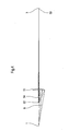
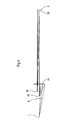
- a first embodiment of the invention is shown with a first Subsystem comprising a first mirror S1 and a second mirror S2.
- the first mirror S1 is a concave mirror and the second mirror S2 is a convex mirror.
- the mirrors are S1 and S2 centered on the optical axis HA.
- the second subsystem comprises a third mirror S3.
- the third mirror is also centered on the optical axis arranged.
- the object in the decentered to the optical axis HA Object plane 1 is shown by the magnifying X-ray microscope mapped the invention in the image plane 3.
- Image plane 3 is close to the second mirror S2 and the decentered to the optical axis between Object plane and first mirror arranged aperture diaphragm B.
- All mirror surfaces of mirrors S1, S2 and S3 are rotationally symmetrical, aspherical mirror segment surfaces.
- the radius of curvature of the first mirror is
- 500 mm, the radius of the second mirror
- 3.5 mm and that of the third mirror
- 4000 mm.
- the second mirror has a relatively small radius of curvature. This is necessary to generate the required large image scale.
- the aperture B lies between the object plane and the first mirror, at a distance of 466 mm from the object plane and has a maximum decentered opening of 60 mm.
- the overall length of the optical system that is to say the distance from the diaphragm plane in which the aperture diaphragm B is arranged, to the third mirror S3 is 2007 mm and the distance from the object plane 1 to the aperture diaphragm B is 466 mm.
- the object and image in the object plane or in the image plane lie decentrally on opposite sides with respect to the optical axis HA.
- the advantage of the three-mirror system presented here can be seen in that with only three mirrors realized a small overall length of less than 2500 mm could be, the overall length, that is, the distance of the aperture diaphragm up to the apex of the third mirror is 2007 mm and the distance of the Object plane 1 from the aperture diaphragm B in the aperture plane is 466 mm.
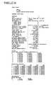
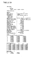
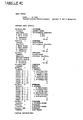
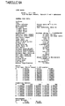
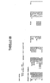
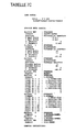
- the general lens data of the embodiment shown in Figure 1 can Table 1a, the summary of the area data, Table 1b and the details from the area data table 1 c in the appendix. All previous and subsequent tables of optical data are data in the ZEMAX format.
- the ZEMAX format is well known to those skilled in the art.
- FIG. 2 shows a four-mirror system with a first subsystem, comprising a first mirror S1 and a second mirror S2 and one second subsystem, comprising a third and a fourth mirror.
- the first mirror S1 is a concave mirror, with the second mirror S2 around a convex mirror, with the third and fourth Mirror S3, S4 each around concave mirror.
- the aperture diaphragm B is in the Embodiment with a small distance in front of the first mirror S1 arranged.
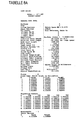
- the general Objective data of this embodiment variant of the invention are in Table 2a specified, the summarized area data in Table 2b and the special area data in Table 2c.
- FIG. 3 again shows a four-mirror system with a first mirror S1, a second mirror S2, a third mirror S3 and a fourth mirror S4 shown.
- the same components as in the previous figures are included the same reference numbers.
- the basic structure of the system according to FIG. 3 is coaxial with rotationally symmetrical spherical or aspherical mirror segment surfaces.
- the object field is arranged decentrally to the optical axis HA. All mirrors are rotationally symmetrical about the optical axis HA.
- the first mirror is a concave mirror with a radius of curvature
- 500 mm
- the second mirror is a convex mirror with a radius of curvature
- 50 mm
- the third mirror is a concave mirror with a radius of curvature
- 166 mm
- the fourth mirror S4 is a concave mirror with a radius of curvature
- 4000 mm.
- the third mirror S3 is spherical.
- the mirror surfaces of mirrors S1, S2 and S4, however, are rotational aspheres.
- the aperture diaphragm B lies between the object plane 1 and the first mirror S1 at a distance of 840.5 mm from the object plane 1 and has a maximum decentered opening of 146 mm.
- the overall length of the optical system which is the distance from the aperture plane B to the image plane 3, is 2116 mm in the present case.
- the general optical data of the system according to FIG. 3 are in Table 3a, the summary of the area data in Table 3b and the special Area data given in Table 3c in the Appendix.
- FIGS. 4 and 5 in turn describe 4-mirror systems with a first subsystem, including mirrors S1, S2 and a second subsystem, including mirrors S3 and S4.
- the same components as in the previous Figures 2 and 3 are again given the same reference numerals.
- the basic structure of the systems according to FIGS. 4 and 5 is coaxial. It is particularly advantageous that the third mirror S3 and the fourth mirror S4 are spherical and only the first mirror S1 and the second mirror S2 comprise rotationally symmetrical aspherical mirror segment surfaces.
- the first mirror S1 is a concave mirror with a radius of curvature
- 500 mm
- the second mirror is a convex mirror with a radius of curvature
- 100 mm
- the third mirror is a concave mirror with a radius of curvature
- 216 mm
- the fourth mirror is a concave mirror with a radius of curvature
- 4000 mm.
- the overall length of the optical system, that is the distance from the diaphragm plane in which the diaphragm B is arranged to the image plane 3 is 2183 mm
- the distance between the object plane 1 and the diaphragm plane is 466 mm.
- the object field of the embodiment shown in FIG. 4 has one Expansion from 30 ⁇ m x at 30 ⁇ m and is slightly off-center, that is arranged off-axis to the optical axis HA.
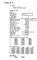
- the general optical data for the embodiment of Figure 4 are in Table 4a, the Summary of optical surface data data in Table 4b and special surface data of the optical surface in Table 4c in the Appendix specified.
- FIG. 5 shows a variant of the exemplary embodiment according to FIG. 4. Essentially all system data has been retained, only the aspherical Areas of mirrors S1 and S2 changed. With this change it is possible expand the object field to a size of 200 ⁇ m x 30 ⁇ m without the Wavefront error and the distortion compared to the embodiment in Figure 4 deteriorates.
- FIG. 6 shows a further variant of a 4-mirror arrangement with a first one Mirror S1, a second mirror S2, a third mirror S3 and a fourth Mirror S4 specified.
- the same components as in Figures 2 to 5 are included the same reference numbers.
- the main difference of the Embodiment according to Figure 6 compared to the embodiment 3, 4th and 5 can be seen in the fact that the second mirror S2 is a concave mirror and above the optical axis HA is used. The bundles after this mirror therefore also run above the optical axis.
- the general optical data can be found in Table 6a, the general Area data Table 6b and the specific area data of the embodiment according to FIG. 6 table 6c in the appendix.
- the exemplary embodiment shown in FIG. 7 corresponds to the second Mirror S2 the embodiment of Figure 6.
- the main difference to the embodiment of Figure 6 is that the third mirror S3 is a convex mirror.
- optical data of the exemplary embodiment according to FIG. 6 can be seen in Table 7a, the general area data table 7b and the special area data table 7c in the appendix.
- the system shown in FIG. 8 is a two-mirror system with a first mirror S1 and a second mirror S2, wherein the first and second mirrors S1, S2 are concave mirrors, respectively.
- the general optical data of the exemplary embodiment according to FIG. 8 are shown in FIG Table 8a, the general area data in Table 8b and the specific ones Area data shown in Table 8c in the Appendix.
- the object-side aperture of the systems according to FIGS. 1 to 8 can be set via the aperture diaphragm B and is 0.0625, for example, for the simulation of conventional projection exposure systems.
- the aperture diaphragm can be set in a range of 0.001 ⁇ NA ⁇ 0.25.
- the object field size, which is illuminated in level 1 by a lighting system (not shown), is, for example, 30 ⁇ m x 30 ⁇ m or 100 x 100 ⁇ m. If, for example, a mask, a so-called reticle, is examined for microlithography, such masks typically have dimensions of 152 x 152 mm. With the reflective X-ray microscope according to the invention, only an image of a section of the mask is possible.
- the object in the object plane 1 is imaged with systems according to FIGS. 1 to 7 300-30000 times enlarged in the image plane 3. Since the aperture diaphragm plane B is accessible, the aperture in the diaphragm plane can be set in a range 0.001 NA NA 0,2 0.25 by means of the aperture diaphragm B. NA here denotes the image-side aperture, hereinafter also referred to as aperture NA image , on the object.
- NA image-side aperture hereinafter also referred to as aperture NA image
- the angle ⁇ of the main beam 5 in the object plane 1 is generally 6 ° to the optical axis of the system. With the aid of the X-ray microscopy according to FIGS. 1 to 7, which comprise more than two mirrors, it is possible to obtain a sufficiently magnifying X-ray microscope objective whose overall length is less than 3000 mm.
- FIG. 9 shows a further embodiment of the invention with a first one Subsystem and a second subsystem.
- the present comprises the first Subsystem a first mirror S1 and a second mirror S2.
- the first Mirror S1 is a concave mirror and the second mirror S2 is a convex mirror.
- the mirrors S1 and S2 are arranged centered on the optical axis HA.
- the second Subsystem comprises a photoemission electron microscope 10.
- the decentered to the optical axis HA arranged object in the object plane 1 is by the first subsystem mapped into an intermediate image Z in an intermediate image plane 2.
- the adjustable aperture diaphragm B is decentred from the optical axis between Object level and first mirror in the high-aperture part of the imaging system arranged. Due to the arrangement in the high-aperture part different numerical apertures can be set very precisely.
- the Photocathode 20 of the photoemission electron microscope is close to that Intermediate image plane 2 arranged. With the photoemission electron microscope (PEEM), the intermediate image Z in the intermediate image plane 2 is enlarged Image shown in image level 3.
- PEEM photoemission electron microscope
- the object-side aperture of the system according to FIG. 9 can be set via the aperture diaphragm B and is 0.0725, for example, for the simulation of conventional projection exposure systems.
- the aperture diaphragm can be set in a range of 0.001 ⁇ NA ⁇ 0.25.
- the object field size, which is illuminated in level 1 by a lighting system (not shown), is, for example, 30 ⁇ m x 30 ⁇ m or 100 x 100 ⁇ m. If, for example, a mask, a so-called reticle, is examined for microlithography, such masks typically have dimensions of 152 x 152 mm. With the reflective X-ray microscope according to the invention, only an image of a section of the mask is possible.
- the object in the object level 1 is mapped 300 - 10,000 times in the image level 3. Since the aperture diaphragm plane B is accessible, as shown in particular in FIG. 9, the aperture in the diaphragm plane can be set in a range 0.001 NA NA 0,2 0.25 by means of the aperture diaphragm B.
- NA here denotes the image-side aperture, hereinafter also referred to as aperture NA image , on the object.
- the angle ⁇ of the main beam 5 in the object plane 1 is 6 ° to the optical axis of the system. With the help of the photoemission electron microscope, it is possible to obtain a sufficiently magnifying X-ray microscope objective whose overall length is less than 2000 mm.
- FIG. 10 shows an inspection system according to the invention, in particular for examining coated EUV masks with a small object field.
- An illumination system 100 illuminates a field 102 in an object plane 101 in a predetermined manner.
- the illumination system 100 can comprise an illumination aperture diaphragm, not shown, for setting the pupil filling degree ⁇ .
- NA illumination represents the numerical aperture in the illumination system, which is specified by the illumination aperture diaphragm
- NA image represents the numerical aperture of the imaging system, which is specified by aperture diaphragm B of the imaging system, here the reflective X-ray microscope.
- an aperture wheel can be arranged in an aperture diaphragm plane.
- the inspection system With the help of the variably adjustable lighting aperture diaphragm, the aperture diaphragm in the imaging system or the aperture wheel, it is possible to use the inspection system according to the invention, the settings in an EUV projection exposure system, in which the mask or reticle is inserted, to simulate and optimize the mask images by evaluating them Setting parameters of the projection exposure system in relation to aperture, art the lighting, etc. This makes the inspection system for much more than just examining masks for defects. Becomes a mask examined for defects, so are the defective areas of the examined EUV mask 104 arranged within the illuminated observed field.
- the beam path is one for the center of the field 102 Tuft of rays shown.
- the main ray 106 from the field plane Beam bundle 108 is at an angle ⁇ with respect to the optical axis HA inclined.
- the angle ⁇ corresponds to the main beam incidence angle in Projection exposure systems on the object, which is preferably 6 °.
- an X-ray microscope according to the invention as an imaging system 110, which is not shown in Figure 10, but an X-ray microscope objective 1 to 9, the object 104 is in the object plane 101 mapped into an image in image plane 112.
- mapping errors by moving at least one of the Aperture diaphragms from the ideal position marked by telecentricity in a non-ideal position, which means that the beam is not strikes the image plane 112 telecentrically.
- the image 114 of the object 104 in the Image plane 112 is enlarged.
- the magnification is preferably in the 300x range up to 1000 x.
- the observation device can be a Camera, in particular a CCD camera, a multi-channel plate or a Be fluorescent screen.
- the observation device cannot with one in FIG shown analysis unit to be executed by the Observation device recorded image, for example, in digital form Evaluation is fed.
- the analysis unit can be a programmable, be a digital computer.
- the programmable digital computer can in turn include control devices which control the aperture diaphragm in the imaging optics, the illumination aperture diaphragm or the diaphragm wheel and the field diaphragms in the inspection system in order to adjust the size and shape of the illuminated object field in the object plane, the pupil filling and the numerical aperture.
- the system can include devices for positioning the object to be examined in the object plane, which is also referred to as the xy plane. This makes it possible to examine different sections of the mask with a small object field, for example of 30 ⁇ m x 30 ⁇ m or 100 ⁇ m x 100 ⁇ m, with a mask size of, for example, 152 x 152 mm 2 .
- the entire mask can be examined with the projection exposure system simulated by the adjustable diaphragms.
- the imaging system is designed in such a way that the first subsystem can easily be separated from the second subsystem. If a larger or smaller object field or a larger or smaller magnification is required, the second subsystem can be exchanged very easily for a second subsystem with larger or lower magnification and / or a larger or smaller object field.
- the entire mask can be roughly examined and the areas critical on the mask can be approached with the aid of the xy positioning device, and these areas can then be examined for defects with a different optical system.
- focus adjustment devices are also provided in a preferred embodiment of the invention, with which the object can move perpendicular to the object plane and images can be recorded at predetermined focus positions above and below the focus.
- Illumination intensity data in the illumination plane for each single picture can be taken.
- intensity data cards can be used with intensity data cards obtained on the basis of simulation calculations or reference data cards, when examining masks or objects that are in a Projection exposure process have produced acceptable results, be compared. In this way, an examination of the mask is on Defects and possibly their repair possible, as well as a qualification of Mask.
- the inspection system according to the invention is not only for defect analysis and the repair of masks suitable for microlithography, but also for local cleaning of the masks by irradiation with light of the wavelength of the Inspection system or optimization of the design of the mask structure and for Process optimization for the exposure process and the system configuration in Projection exposure systems.
- FIG. 1 A schematic diagram of the entire inspection system is shown in FIG.
- the Light from an EUV light source 100 is collected by and over a collector 102 Mirrors 104, 106 of the lighting system on the object plane 108 in which the object to be examined is directed.
- the bundle of rays of the Lighting system 110 does not fall on the object in FIG Object plane 108, but at an angle.
- the main beam angle of the beam bundle is identical to the main beam angle below that the projection exposure system is also operated. This is preferably Angle ⁇ relative to normal 112 in a first exemplary embodiment is 6 °.
- the lighting system 110 are in the beam path from the collector 102 to Object plane 108, an illumination aperture diaphragm 120 and a field diaphragm 122 arranged.
- the object in the object plane 108 that illuminates under reflection with an imaging system according to the invention in an image plane 130 shown in which the object can be observed.
- the illustration is in this embodiment in two stages, with an intermediate image Z.
- the first Imaging system subsystem 150 includes a first mirror 152 and a second mirror 154. That from the first subsystem into the intermediate image plane depicted intermediate image of the object in the object plane, preferably the one to examining mask is enlarged by means of a second subsystem 156 in the image plane 130 is imaged.
- the aperture diaphragm 154 in the imaging system is located in the beam path from the object level to the intermediate image level between object level 108 and first mirror 152 of first subsystem 150.
- the second subsystem can comprise, for example, an optical system, be at least one mirror, a PEEM. That was detailed earlier described.
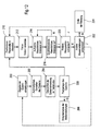
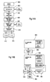
- FIG. 12 shows an exemplary measurement sequence for examining an object using the inspection system according to the invention.
- the system setting is entered, for example the NA mapping , the NA lighting and the obscuration or field diaphragm.
- the diaphragms are then set in a second step 202.
- the system settings are then checked in a step 204 using a test structure, for example a linear structure in the x or y direction.
- the system is fine-tuned in a step 206 using the test structure.
- the measuring point is positioned in the measuring field, that is the area of the object to be examined, in which, for example, the xy table is moved to the corresponding point.
- documentation of the measurement settings can also be carried out in a step 208 before positioning in the measurement field.
- Step 212 set the focus. If the focus is found in step 212, then either a measurement image was recorded in step 214 or the focus as before drive through described, d. H. Measurement images for different z positions added. A quality control is carried out after each measurement image in step 216 the same instead of or the different focus positions are assigned Measured images assessed in terms of quality. Do these suffice Quality requirements, if available, the object will be sent to another Move the measuring point and there again the series of measurements as previously described added. If the quality control leads to a negative result, then a new measurement image was recorded at the same location or a large number of Measurement images that are assigned to different z positions.
- step 222 If there is no further measuring position 220, either in step 222 the system settings changed or the measurement ended in step 224 become.
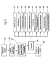
- FIG. 13 shows possible evaluations of using the inspection system obtained measurement images or measurement information, for example with the help a computer device can be performed.
- the selected measurement image 300 which is a function of the location on the examining object in the object plane, d. H. in the x-y plane, as well as in the z direction, if different measurement images above and below the focal plane can be recorded in a step 302 both what the location on the Sample, i.e. the x-y position, i.e. in terms of the region as well as in with respect to the z position, i.e. selected in relation to the cut and then be analyzed.
- the selected data can be numeric edited and certain representations calculated as in step 304 specified. For example, the data can be fitted, interpolated, correlated, smoothed, filtered or mirrored.
- the preparation of the data by Calculation or preparation in step 304 can also, for. B. automated characterized in terms of quality in step 306 become.
- step 310 As an alternative to or in addition to the output of key figures on quality different representations are made in step 310. So is one Image display of the intensity in the x, y direction possible or a contour plot. This is marked with reference numbers 312 and 314. Alternatively, the profiles are shown for the cuts or the line width over the defocus, d. H. the movement in the z direction. This is marked with 316 and 318. Of the line width can also be displayed above the threshold. This is with Reference number 320 marked. They are alternative types of representation Process window identified by reference number 322 and a display of the Simulation data for measurement data for resist development, what with reference number 324 is marked. A comparison of several measurements is also possible a representation of the contrast via the defocusing, i.e. the movement in the z direction.
- FIGS. 14a to 14c show possible areas of application for the invention Inspection system shown.
- Figure 14a shows the use of the EUV inspection system for example in the manufacture of mask blanks, d. H. Mask blanks.
- the substrate manufactured according to step 400 which is usually a Glass substrate can, in step 402 with the help of the EUV inspection system according to the invention be checked for its quality. Is this Quality is sufficient, so the substrate in step 404 with EUV mirror layers coated. These mirror layers are now in step 406 inspected for defects, the entire area.
- an inspection module is used, for example one for EUV imaging system parallel imaging system that uses visible light is working.
- step 408 Defects can be examined in more detail with the help of the EUV inspection system. For this the mask previously examined on the entire surface with an x-y positioning device move to the defects and target these areas the mask with the EUV inspection system. Is the quality of the mask sufficient after step 410 after the EUV inspection, the mask are delivered in accordance with step 412 or is discarded in accordance with step 414.
- FIG. 14b shows another area of application of the EUV inspection system according to the invention use in mask production.
- the incoming 14b in step 450 with the aid of the coated mask substrate EUV inspection system to be examined in the incoming goods inspection. Is the If the mask is of sufficient quality, this can be done in a subsequent step 452 be structured.
- the entire structured mask according to step 452 can be in Step 454 in turn was qualitatively examined using the EUV inspection system become.
- there is initially Defect inspection of the entire mask area with an inspection system that works with visible light, for example, as well as a CD measurement, also with a system in the visible or UV or VUV wavelength range is working.
- the EUV inspection system in the case of defect inspection or CD measurement, the is not carried out with EUV radiation, defects, it can EUV inspection system according to the invention can be used there classify any defects found. Is due to the EUV inspection the defects the quality of the masks after defect inspection for sufficient found, it can be delivered according to step 456. Is the mask insufficient quality, the mask can be placed on the corresponding defect proceed and in step 458 it is examined whether there is a repair is possible or not. If no repair is possible, the mask is made according to Step 460 discarded. If a repair is possible, this is done according to step 462 carried out and again subjected to the EUV inspection. Now surrender sufficient quality data, so the repaired mask can be delivered.
- FIG. 14 c shows the area of application of the EUV inspection system according to the invention the use of such an inspection system in the Wafer fab.
- the mask can initially be one according to step 500 Received inspection.
- the mask ages.
- the masks can be removed periodically using the EUV inspection system according to the invention on their quality after aging or after storage in accordance with step 504. For this the mask initially again with radiation in the visible or UV or VUV wavelength range fully examined for defects. In the places, at If defects occur, an EUV inspection is carried out. Is the Mask quality is still sufficient, so the mask can continue in production be used.
- the EUV inspection reveals that the mask is qualitative Requirements are no longer sufficient, it can be examined whether the defect is repairable. This step is referred to as step 506. Separates one Repair, the mask is removed according to step 508 from the production process taken.
- the mask is activated in accordance with step 510 repaired and after the repair again using the EUV inspection system inspected.
- the defect is classified after repair and at of sufficient quality, the mask in turn is transferred to the production process and discarded if the quality is insufficient.
Landscapes
- Engineering & Computer Science (AREA)
- Physics & Mathematics (AREA)
- High Energy & Nuclear Physics (AREA)
- Chemical & Material Sciences (AREA)
- Nanotechnology (AREA)
- General Engineering & Computer Science (AREA)
- Theoretical Computer Science (AREA)
- Crystallography & Structural Chemistry (AREA)
- Spectroscopy & Molecular Physics (AREA)
- Mathematical Physics (AREA)
- Analysing Materials By The Use Of Radiation (AREA)
- Lenses (AREA)
- Exposure Of Semiconductors, Excluding Electron Or Ion Beam Exposure (AREA)
- Investigating Or Analysing Materials By Optical Means (AREA)
Abstract
- einem Beleuchtungssystem zur Ausleuchtung eines Feldes in einer Objektebene (1), wobei
- in der Objektebene innerhalb des ausgeleuchteten Feldes das zu untersuchende Objekt angeordnet ist;
- einem Abbildungssystem für Wellenlängen ≤ 100 nm zur vergrößernden Abbildung wenigstens eines Ausschnittes des Objektes in eine Bildebene (3);
- einem in der Bildebene (3) angeordneten Bildaufnahmesystem.
Description
US 5,022,064
bekannt geworden und ein Inspektionssystem mit reflektivem Röntgenstrahlmikroskop aus der
JP 2001116900.
EP-A-0628806
JP-A-4-321047
bekannt geworden. Der Inhalt dieser Schriften wird vollumfänglich in den Offenbarungsgehalt dieser Anmeldung mit aufgenommen. In diesen Systemen ist allerdings nur die Untersuchung von Transmissionsmasken beschrieben; eine Untersuchung von Reflexionsmasken, wie in der EUV-Lithographie verwendet, ist nicht erwähnt.
- Figur 1:
- die Gesamtansicht eines erfindungsgemäßen ersten Röntgenmikroskopobjektives mit einem ersten Subsystem, umfassend einen ersten und einen zweiten Spiegel und einem zweiten Subsystem, umfassend einen dritten Spiegel
- Figur 2:
- ein zweites Röntgenmikroskop, umfassend ein erstes Subsystem mit erstem und zweitem Spiegel sowie ein zweites Subsystem, umfassend einen dritten und einen vierten Spiegel.
- Figur 3:
- ein drittes Röntgenmikroskop, umfassend ein erstes Subsystem mit einem ersten und zweitem Spiegel sowie ein zweites Subsystem, umfassend einen dritten und vierten Spiegel, wobei der dritte Spiegel sphärisch ausgestaltet ist und die Blende zwischen Objektebene und erstem Spiegel liegt.
- Figur 4:
- ein viertes Röntgenmikroskop, umfassend ein erstes Subsystems mit erstem und zweitem Spiegel sowie ein zweites Subsystem, umfassend einen dritten und vierten Spiegel, wobei der dritte und vierte Spiegel sphärisch ausgestaltet sind und die Objektfeldgröße 30 µm x 30 µm ist.
- Figur 5:
- ein fünftes Röntgenmikroskop, umfassend ein erstes Subsystem mit erstem und zweitem Spiegel sowie ein zweites Subsystem mit drittem und viertem Spiegel, wobei der dritte und vierte Spiegel sphärisch ausgestaltet sind und das Objektfeld eine Ausdehnung von 200 µm x 30 µm aufweist.
- Figur 6:
- ein sechstes Röntgenmikroskop, umfassend ein erstes Subsystem mit erstem und zweitem Spiegel sowie ein zweites Subsystem, umfassend einen dritten und vierten Spiegel, wobei der dritte und vierte Spiegel sphärisch ausgebildet ist und alle Spiegel Konkavspiegel sind.
- Figur 7:
- ein siebtes Röntgenmikroskop, umfassend ein erstes Subsystem mit erstem und zweitem Spiegel sowie ein zweites Subsystem, umfassend einen dritten und vierten Spiegel, wobei der erste Spiegel ein Konkavspiegel, der zweite Spiegel ein Konkavspiegel, der dritte Spiegel ein Konvexspiegel und der vierte Spiegel ein Konkavspiegel ist.
- Figur 8:
- ein Zweispiegelsystem, wobei der erste Spiegel ein Konkavspiegel und der zweite Spiegel ein Konkavspiegel ist.
- Figur 9:
- die Gesamtansicht eines erfindungsgemäßen ersten Röntgenmikroskopobjektives mit einem ersten Subsystem, umfassend einen ersten und einen zweiten Spiegel und einem zweiten Subsystem, umfassend ein Photoemissions-Elektronenmikroskop.
- Figur 10:
- ein Inspektionssystem für EUV-Masken mit einem erfindungsgemäßen Röntgenmikroskop in schematischer Darstellung
- Figur 11:
- ein Inspektionssystem, wobei die einzelnen Komponenten des Inspektionssystems näher gezeigt sind
- Figur 12:
- Flussdiagramm für die Durchführung einer Messung
- Figur 13
- mögliche Bearbeitungen der aufgenommenen Bilder
- Figur 14a-c
- mögliche Einsatzgebiete des erfindungsgemäßen Inspektionssystems
Claims (29)
- Inspektionssystem für die Untersuchung von Objekten, insbesondere Masken für die Mikrolithographie mit Wellenlängen < 100 nm, vorzugsweise < 30 nm, mit1.1 einem Beleuchtungssystem zur Ausleuchtung eines Feldes in einer Objektebene (1), wobei1.2 in der Objektebene innerhalb des ausgeleuchteten Feldes das zu untersuchende Objekt angeordnet ist;1.3 einem Abbildungssystem für Wellenlängen ≤ 100 nm zur vergrößernden Abbildung wenigstens eines Ausschnittes des Objektes in eine Bildebene (3);1.4 einem in der Bildebene (3) angeordneten Bildaufnahmesystem.
- Inspektionssystem gemäß Anspruch 1, dadurch gekennzeichnet, daß das Inspektionssystem Positioniereinrichtungen zum Positionieren des Objektes in der Objektebene umfaßt.
- Inspektionssystem gemäß einem der Ansprüche 1 bis 2, dadurch gekennzeichnet, daß das Abbildungssystem eine einstellbare Aperturblende (B) umfaßt.
- Inspektionssystem gemäß einem der Ansprüche 1 bis 3, dadurch gekennzeichnet, daß das Beleuchtungssystem eine einstellbare Beleuchtungsaperturblende in einer Ebene, die konjugiert zur Ebene der Aperturblende (B) im Abbildungssystem ist, umfaßt.
- Inspektionssystem gemäß einem der Ansprüche 1 bis 3, dadurch gekennzeichnet, daß das Beleuchtungssystem oder das Abbildungssystem eine Obskurationsblende in oder nahe der Blendenebene (B) oder einer Ebene, die konjugiert zur Blendenebene (B) ist, umfaßt.
- Inspektionssystem gemäß einem der Ansprüche 1 bis 5, dadurch gekennzeichnet, daß das Beleuchtungssystem eine einstellbare Feldblende umfaßt.
- Inspektionssystem gemäß einem der Ansprüche 1 bis 6, dadurch gekennzeichnet, daß das Bildaufnahmesystem eine Analyseeinheit zur Analyse der Bilder des Objektes in der Bildebene (3) umfaßt.
- Inspektionssystem gemäß einem der Ansprüche 1 bis 7, dadurch gekennzeichnet, daß das Inspektionssystem Fokuseinstelleinrichtungen umfaßt.
- Inspektionssystem gemäß Anspruch 8, dadurch gekennzeichnet, daß die Fokuseinstelleinrichtungen Verfahreinrichtungen zum Verfahren des Objektes in senkrechter Richtung zur Objektebene (1) umfassen.
- Inspektionssystem gemäß Anspruch 8 oder 9, dadurch gekennzeichnet, daß das Bildaufnahmesystem Bilder an vorbestimmten Fokuspositionen, in die das Objekt durch die Fokuseinstelleinrichtung verbracht wird, aufnimmt.
- Inspektionssystem gemäß einem der Ansprüche 7 bis 10, dadurch gekennzeichnet, daß die Analyseeinheit eine Mikrocomputereinrichtung umfaßt.
- Inspektionssystem gemäß einem der Ansprüche 1 bis 11, dadurch gekennzeichnet, daß das Abbildungssystem für Wellenlängen ≤ 100 nm ein reflektives Röntgenmikroskop umfaßt.
- Inspektionssystem gemäß Anspruch 12, dadurch gekennzeichnet, daß das reflektive Röntgenmikroskop ein reflektives Röntgenmikroskop gemäß einem der Ansprüche 1 bis 25 umfaßt.
- Inspektionssystem gemäß Anspruch 12, dadurch gekennzeichnet, daß das reflektive Röntgenmikroskop ein reflektives Röntgenmikroskop gemäß Anspruch 8 oder einem der Ansprüche 14 bis 25 umfaßt und daß die Fokuseinstelleinrichtungen Verfahreinrichtungen zum Verfahren des zweiten Subsystems in senkrechter Richtung zur Zwischenbildebene (2) umfassen.
- Inspektionssystem gemäß Anspruch 12, dadurch gekennzeichnet, daß das reflektive Röntgenmikroskop ein reflektives Röntgenmikroskop gemäß Anspruch 8 oder einem der Ansprüche 14 bis 25 umfaßt und daß die Fokuseinstelleinrichtungen Verfahreinrichtungen zum Verfahren des zweiten Subsystems in senkrechter Richtung zur Zwischenbildebene (2) und zum Verfahren des Objektes in senkrechter Richtung zur Objektebene (1) umfassen.
- Inspektionssystem gemäß einem der Ansprüche 1 bis 15, dadurch gekennzeichnet, daß wenigstens ein Teil des Inspektionssystems im Vakuum oder in einem Schutzgas angeordnet ist.
- Inspektionssystem gemäß einem der Ansprüche 1 bis 16, dadurch gekennzeichnet, daß das Inspektionssystem des weiteren ein zum Abbildungssystem für Wellenlängen ≤ 100 nm paralleles Hilfsbeobachtungssystem für Wellenlängen ≥ 100 nm zur Abbildung wenigstens eines Teiles des Objektes in eine weitere Bildebene umfaßt.
- Inspektionssystem gemäß Anspruch 17, dadurch gekennzeichnet, daß das Hilfsbeobachtungssystem parfokal und/oder parzentriert angeordnet ist.
- Verfahren zur Inspektion von Objekten, insbesondere Masken für die Mikrolithographie mit Wellenlängen ≤ 100 nm mit folgenden Schritten:19.1 in der Objektebene wird mit einem Beleuchtungssystem ein Feld ausgeleuchtet;19.2 das zu untersuchende Objekt wird mit Positioniereinrichtungen in das ausgeleuchtete Feld verbracht;19.3 das zu untersuchende Objekt wird mit einem reflektiven Röntgenmikroskop für Wellenlängen ≤ 100 nm in eine Bildebene (3) abgebildet;19.4 die Bilder des Objektes in der Bildebene (3) werden von einem Bildaufnahmesystem aufgenommen.
- Verfahren gemäß Anspruch 19, dadurch gekennzeichnet, daß die von dem Bildaufnahmesystem aufgenommenen Bilder mit einer Analyseeinheit auf charakteristische Größen des Objektes hin ausgewertet werden.
- Verfahren gemäß Anspruch 19 oder 20, dadurch gekennzeichnet, daß das Objekt mit einer Fokuseinstellvorrichtung senkrecht zur Objektebene (1) verfahren wird und Bilder an vorbestimmten Fokuspositionen ober- und unterhalb des Fokus aufgenommen werden.
- Verfahren gemäß einem der Ansprüche 19 bis 21, dadurch gekennzeichnet, daß die numerische Apertur mit der Aperturblende (B) und mit der Beleuchtungsaperturblende so eingestellt wird, daß sich eine mit der Projektionsbelichtungsanlage optisch äquivalente Apertur ergibt.
- Verfahren gemäß einem der Ansprüche 19 bis 22, dadurch gekennzeichnet, daß das Verfahren mit einem Inspektionssystem gemäß einem der Ansprüche 26 bis 43 durchgeführt wird.
- Verfahren gemäß einem der Ansprüche 19 bis 22, dadurch gekennzeichnet, daß das Verfahren mit einem Inspektionssystem gemäß Anspruch 39 durchgeführt wird und zur Fokuseinstellung das zweite Subsystem in senkrechter Richtung zur Zwischenbildebene (2) verfahren wird und Bilder an vorbestimmten Fokuspositionen oder ober- und unterhalb des Fokus aufgenommen werden.
- Verfahren gemäß einem der Ansprüche 19 bis 22, dadurch gekennzeichnet, daß das Verfahren mit einem Inspektionssystem gemäß Anspruch 40 durchgeführt wird und zur Fokuseinstellung das Objekt senkrecht zur Objektebene (1) verfahren wird und / oder das zweite Subsystem in senkrechter Richtung zur Zwischenbildebene (2) verfahren wird und Bilder an vorbestimmten Fokuspositionen oder ober- und unterhalb des Fokus aufgenommen werden.
- Verwendung eines Inspektionssystems gemäß einem der Ansprüche 3 bis 19 zur Defektanalyse von Masken für die Mikrolithographie mit Wellenlängen ≤ 100 nm.
- Verwendung eines Inspektionssystems gemäß einem der Ansprüche 3 bis 19 zur Kontrolle von Reparaturen von Masken für die Mikrolithographie mit Wellenlängen ≤ 100 nm.
- Verwendung eines Inspektionssystems gemäß einem der Ansprüche 3 bis 19 zur Prozeßoptimierung für den Belichtungsprozeß in Projektionsbelichtungsanlagen.
- Verwendung eines Inspektionssystems gemäß einem der Ansprüche 3 bis 19 zur Systemkonfiguration einer Projektionsbelichtungsanlage.
Applications Claiming Priority (5)
| Application Number | Priority Date | Filing Date | Title |
|---|---|---|---|
| DE10220815 | 2002-05-10 | ||
| DE10220815A DE10220815A1 (de) | 2002-05-10 | 2002-05-10 | Reflektives Röntgenmikroskop und Inspektionssystem zur Untersuchung von Objekten mit Wellenlängen 100 nm |
| DE10220816 | 2002-05-10 | ||
| DE10220816A DE10220816A1 (de) | 2002-05-10 | 2002-05-10 | Reflektives Röntgenmikroskop und Inspektionssystem zur Untersuchung von Objekten mit Wellenlängen 100 nm |
| EP03740130A EP1446813B1 (de) | 2002-05-10 | 2003-05-08 | Reflektives roentgenmikroskop zur untersuchung von objekten mit wellenlaengen = 100nm in reflexion |
Related Parent Applications (1)
| Application Number | Title | Priority Date | Filing Date |
|---|---|---|---|
| EP03740130A Division EP1446813B1 (de) | 2002-05-10 | 2003-05-08 | Reflektives roentgenmikroskop zur untersuchung von objekten mit wellenlaengen = 100nm in reflexion |
Publications (2)
| Publication Number | Publication Date |
|---|---|
| EP1455365A2 true EP1455365A2 (de) | 2004-09-08 |
| EP1455365A3 EP1455365A3 (de) | 2014-12-17 |
Family
ID=29421498
Family Applications (2)
| Application Number | Title | Priority Date | Filing Date |
|---|---|---|---|
| EP03740130A Expired - Lifetime EP1446813B1 (de) | 2002-05-10 | 2003-05-08 | Reflektives roentgenmikroskop zur untersuchung von objekten mit wellenlaengen = 100nm in reflexion |
| EP04013866.1A Withdrawn EP1455365A3 (de) | 2002-05-10 | 2003-05-08 | Reflektives Röntgenmikroskop und Inspektionssystem zur Untersuchung von Objekten mit Wellenlängen 100nm |
Family Applications Before (1)
| Application Number | Title | Priority Date | Filing Date |
|---|---|---|---|
| EP03740130A Expired - Lifetime EP1446813B1 (de) | 2002-05-10 | 2003-05-08 | Reflektives roentgenmikroskop zur untersuchung von objekten mit wellenlaengen = 100nm in reflexion |
Country Status (7)
| Country | Link |
|---|---|
| US (1) | US7623620B2 (de) |
| EP (2) | EP1446813B1 (de) |
| JP (2) | JP4639352B2 (de) |
| AT (1) | ATE488013T1 (de) |
| AU (1) | AU2003268097A1 (de) |
| DE (1) | DE50313254D1 (de) |
| WO (1) | WO2003096356A2 (de) |
Cited By (5)
| Publication number | Priority date | Publication date | Assignee | Title |
|---|---|---|---|---|
| WO2009118130A1 (de) * | 2008-03-27 | 2009-10-01 | Carl Zeiss Sms Gmbh | Mikroskop und mikroskopierverfahren zur untersuchung eines reflektierenden objektes |
| WO2010148293A2 (en) | 2009-06-19 | 2010-12-23 | Kla-Tencor Corporation | Euv high throughput inspection system for defect detection on patterned euv masks, mask blanks, and wafers |
| CN101995408A (zh) * | 2009-08-21 | 2011-03-30 | Asml荷兰有限公司 | 检查方法和设备 |
| DE102023129681A1 (de) * | 2023-10-27 | 2025-04-30 | Carl Zeiss Smt Gmbh | Verfahren und Steuervorrichtung zum Analysieren eines Bildes eines Rohlings einer Photomaske für die Mikrolithographie |
| WO2025224253A1 (en) | 2024-04-25 | 2025-10-30 | Carl Zeiss Smt Gmbh | Method for highly accurately determining the location of a structure, apparatus for carrying out the method and metrology system for measuring lithography masks |
Families Citing this family (26)
| Publication number | Priority date | Publication date | Assignee | Title |
|---|---|---|---|---|
| US7351980B2 (en) * | 2005-03-31 | 2008-04-01 | Kla-Tencor Technologies Corp. | All-reflective optical systems for broadband wafer inspection |
| WO2007020004A1 (de) * | 2005-08-17 | 2007-02-22 | Carl Zeiss Smt Ag | Projektionsobjektiv und verfahren zur optimierung einer systemblende eines projektionsobjektivs |
| US7564564B2 (en) * | 2006-08-22 | 2009-07-21 | Artium Technologies, Inc. | Automatic set-up for instrument functions |
| DE102006044202A1 (de) * | 2006-09-15 | 2008-05-21 | Fahrzeugwerk Bernard Krone Gmbh | Dolly-Achse |
| US20080144167A1 (en) * | 2006-12-13 | 2008-06-19 | General Electric Company | Optical imaging system and method for high speed and high resolution |
| DE102007062198A1 (de) | 2007-12-21 | 2009-06-25 | Carl Zeiss Microimaging Gmbh | Katoptrisches Objektiv zur Abbildung eines im Wesentlichen linienförmigen Objektes |
| KR101535230B1 (ko) * | 2009-06-03 | 2015-07-09 | 삼성전자주식회사 | Euv 마스크용 공간 영상 측정 장치 및 방법 |
| KR101422256B1 (ko) | 2009-06-19 | 2014-07-22 | 케이엘에이-텐코어 코오포레이션 | 극자외선 마스크 블랭크들상의 결함들을 검출하기 위한 검사 시스템들 및 방법들 |
| DE102010009022B4 (de) * | 2010-02-22 | 2019-10-24 | Carl Zeiss Smt Gmbh | Beleuchtungssystem sowie Projektionsobjektiv einer Maskeninspektionsanlage |
| DE102010029049B4 (de) | 2010-05-18 | 2014-03-13 | Carl Zeiss Smt Gmbh | Beleuchtungsoptik für ein Metrologiesystem für die Untersuchung eines Objekts mit EUV-Beleuchtungslicht sowie Metrologiesystem mit einer derartigen Beleuchtungsoptik |
| DE102010025033B4 (de) * | 2010-06-23 | 2021-02-11 | Carl Zeiss Smt Gmbh | Verfahren zur Defekterkennung und Reparatur von EUV-Masken |
| DE102010047050B4 (de) * | 2010-09-29 | 2021-09-16 | Carl Zeiss Smt Gmbh | Verfahren zur Charakterisierung einer Struktur auf einer Maske und Vorrichtung zur Durchführung des Verfahrens |
| US8837041B2 (en) * | 2010-11-23 | 2014-09-16 | Carl Zeiss Smt Gmbh | Magnifying imaging optical system and metrology system with an imaging optical system of this type |
| JP4761588B1 (ja) * | 2010-12-01 | 2011-08-31 | レーザーテック株式会社 | Euvマスク検査装置 |
| EP2663897A4 (de) * | 2011-01-11 | 2018-01-03 | KLA-Tencor Corporation | Vorrichtung zur euv-bildgebung und verfahren zu ihrer verwendung |
| DE102011003302A1 (de) | 2011-01-28 | 2012-08-02 | Carl Zeiss Smt Gmbh | Vergrößerte abbildende Optik sowie Metrologiesystem mit einer derartigen abbildenden Optik |
| DE102011005881A1 (de) | 2011-03-22 | 2012-05-03 | Carl Zeiss Smt Gmbh | Verfahren zur Einstellung eines Beleuchtungssystems einer Projektionsbelichtungsanlage für die Projektionslithographie |
| DE102011079382B4 (de) | 2011-07-19 | 2020-11-12 | Carl Zeiss Smt Gmbh | Verfahren und Vorrichtung zum Analysieren und zum Beseitigen eines Defekts einer EUV Maske |
| DE102013204445A1 (de) * | 2013-03-14 | 2014-09-18 | Carl Zeiss Smt Gmbh | Vergrößernde abbildende Optik sowie EUV-Maskeninspektionssystem mit einer derartigen abbildenden Optik |
| DE102013212613B4 (de) | 2013-06-28 | 2015-07-23 | Carl Zeiss Sms Gmbh | Beleuchtungsoptik für ein Metrologiesystem sowie Metrologiesystem mit einer derartigen Beleuchtungsoptik |
| DE102014219755A1 (de) | 2013-10-30 | 2015-04-30 | Carl Zeiss Smt Gmbh | Reflektives optisches Element |
| JP6320550B2 (ja) * | 2014-02-21 | 2018-05-09 | パウル・シェラー・インスティトゥート | コヒーレント回折イメージング方法を使用した、反射モードにおける装置 |
| EP3518041A1 (de) * | 2018-01-30 | 2019-07-31 | ASML Netherlands B.V. | Inspektionsvorrichtung und inspektionsverfahren |
| JP2020173296A (ja) * | 2019-04-08 | 2020-10-22 | 株式会社ニューフレアテクノロジー | Euvマスクのパターン検査装置及びeuvマスクのパターン検査方法 |
| CN113994485B (zh) * | 2019-05-10 | 2026-03-24 | 日亚化学工业株式会社 | 图像显示装置的制造方法以及图像显示装置 |
| DE102023204172B4 (de) * | 2023-05-05 | 2026-02-19 | Carl Zeiss Smt Gmbh | Optisches System für ein Metrologiesystem sowie Metrologiesystem mit einem derartigen optischen System |
Family Cites Families (25)
| Publication number | Priority date | Publication date | Assignee | Title |
|---|---|---|---|---|
| JPS612124A (ja) | 1984-06-14 | 1986-01-08 | Canon Inc | 結像光学系 |
| EP0947882B1 (de) * | 1986-07-11 | 2006-03-29 | Canon Kabushiki Kaisha | Verkleinerndes Projektionsbelichtungssystem des Reflexionstyps für Röntgenstrahlung |
| JP2603225B2 (ja) * | 1986-07-11 | 1997-04-23 | キヤノン株式会社 | X線投影露光装置及び半導体製造方法 |
| US4912737A (en) | 1987-10-30 | 1990-03-27 | Hamamatsu Photonics K.K. | X-ray image observing device |
| JPH02210299A (ja) | 1989-02-10 | 1990-08-21 | Olympus Optical Co Ltd | X線用光学系及びそれに用いる多層膜反射鏡 |
| JPH0782117B2 (ja) * | 1989-02-23 | 1995-09-06 | オリンパス光学工業株式会社 | 反射型結像光学系 |
| JP2865257B2 (ja) | 1989-03-07 | 1999-03-08 | オリンパス光学工業株式会社 | シュヴアルツシルド光学系 |
| US5063586A (en) | 1989-10-13 | 1991-11-05 | At&T Bell Laboratories | Apparatus for semiconductor lithography |
| JP2945431B2 (ja) | 1990-03-01 | 1999-09-06 | オリンパス光学工業株式会社 | 結像型x線顕微鏡 |
| JP2921038B2 (ja) | 1990-06-01 | 1999-07-19 | キヤノン株式会社 | X線を用いた観察装置 |
| DE4027285A1 (de) | 1990-08-29 | 1992-03-05 | Zeiss Carl Fa | Roentgenmikroskop |
| US5291339A (en) | 1990-11-30 | 1994-03-01 | Olympus Optical Co., Ltd. | Schwarzschild optical system |
| JPH04321047A (ja) | 1991-01-21 | 1992-11-11 | Nikon Corp | フォトマスク検査装置及びフォトマスク検査方法 |
| JPH04353800A (ja) * | 1991-05-31 | 1992-12-08 | Olympus Optical Co Ltd | 軟x線顕微鏡 |
| US5177774A (en) * | 1991-08-23 | 1993-01-05 | Trustees Of Princeton University | Reflection soft X-ray microscope and method |
| JPH06237016A (ja) * | 1993-02-09 | 1994-08-23 | Matsushita Electric Ind Co Ltd | 光ファイバモジュールおよびその製造方法 |
| JPH0728226A (ja) | 1993-04-30 | 1995-01-31 | Internatl Business Mach Corp <Ibm> | 領域的イメージを測定する装置及び方法 |
| JP3336361B2 (ja) * | 1993-06-11 | 2002-10-21 | 株式会社ニコン | 縮小投影露光用反射型x線マスクの検査装置および検査方法 |
| US6438199B1 (en) | 1998-05-05 | 2002-08-20 | Carl-Zeiss-Stiftung | Illumination system particularly for microlithography |
| DE19923609A1 (de) * | 1998-05-30 | 1999-12-02 | Zeiss Carl Fa | Ringfeld-4-Spiegelsysteme mit konvexem Primärspiegel für die EUV-Lithographie |
| US6328482B1 (en) * | 1998-06-08 | 2001-12-11 | Benjamin Bin Jian | Multilayer optical fiber coupler |
| JP4374735B2 (ja) * | 1999-08-11 | 2009-12-02 | 株式会社ニコン | 反射型軟x線顕微鏡、マスク検査装置及び反射マスクの製造方法 |
| EP1126477A3 (de) * | 2000-02-14 | 2003-06-18 | Leica Microsystems Lithography GmbH | Verfahren zur Untersuchung von Strukturen auf einem Halbleiter-Substrat |
| JP2002329473A (ja) * | 2001-02-27 | 2002-11-15 | Jeol Ltd | X線分光器を備えた透過型電子顕微鏡 |
| DE10319269A1 (de) * | 2003-04-25 | 2004-11-25 | Carl Zeiss Sms Gmbh | Abbildungssystem für ein, auf extrem ultravioletter (EUV) Strahlung basierendem Mikroskop |
-
2003
- 2003-05-08 EP EP03740130A patent/EP1446813B1/de not_active Expired - Lifetime
- 2003-05-08 AU AU2003268097A patent/AU2003268097A1/en not_active Abandoned
- 2003-05-08 AT AT03740130T patent/ATE488013T1/de active
- 2003-05-08 WO PCT/EP2003/004803 patent/WO2003096356A2/de not_active Ceased
- 2003-05-08 EP EP04013866.1A patent/EP1455365A3/de not_active Withdrawn
- 2003-05-08 DE DE50313254T patent/DE50313254D1/de not_active Expired - Lifetime
- 2003-05-08 JP JP2004504243A patent/JP4639352B2/ja not_active Expired - Lifetime
-
2004
- 2004-11-08 US US10/983,362 patent/US7623620B2/en not_active Expired - Lifetime
-
2009
- 2009-11-09 JP JP2009255986A patent/JP2010032542A/ja active Pending
Cited By (7)
| Publication number | Priority date | Publication date | Assignee | Title |
|---|---|---|---|---|
| WO2009118130A1 (de) * | 2008-03-27 | 2009-10-01 | Carl Zeiss Sms Gmbh | Mikroskop und mikroskopierverfahren zur untersuchung eines reflektierenden objektes |
| WO2010148293A2 (en) | 2009-06-19 | 2010-12-23 | Kla-Tencor Corporation | Euv high throughput inspection system for defect detection on patterned euv masks, mask blanks, and wafers |
| EP2443440B1 (de) * | 2009-06-19 | 2019-11-27 | KLA-Tencor Corporation | Euv-prüfsystem mit hohem durchlauf zur fehlererkennung auf strukturierten euv-masken, maskenrohlinge und wafer |
| CN101995408A (zh) * | 2009-08-21 | 2011-03-30 | Asml荷兰有限公司 | 检查方法和设备 |
| CN101995408B (zh) * | 2009-08-21 | 2014-12-31 | Asml荷兰有限公司 | 检查方法和设备 |
| DE102023129681A1 (de) * | 2023-10-27 | 2025-04-30 | Carl Zeiss Smt Gmbh | Verfahren und Steuervorrichtung zum Analysieren eines Bildes eines Rohlings einer Photomaske für die Mikrolithographie |
| WO2025224253A1 (en) | 2024-04-25 | 2025-10-30 | Carl Zeiss Smt Gmbh | Method for highly accurately determining the location of a structure, apparatus for carrying out the method and metrology system for measuring lithography masks |
Also Published As
| Publication number | Publication date |
|---|---|
| US7623620B2 (en) | 2009-11-24 |
| EP1446813A2 (de) | 2004-08-18 |
| JP2005525565A (ja) | 2005-08-25 |
| EP1455365A3 (de) | 2014-12-17 |
| ATE488013T1 (de) | 2010-11-15 |
| WO2003096356A3 (de) | 2004-05-21 |
| JP2010032542A (ja) | 2010-02-12 |
| AU2003268097A8 (en) | 2003-11-11 |
| DE50313254D1 (de) | 2010-12-23 |
| JP4639352B2 (ja) | 2011-02-23 |
| AU2003268097A1 (en) | 2003-11-11 |
| WO2003096356A2 (de) | 2003-11-20 |
| EP1446813B1 (de) | 2010-11-10 |
| US20050201514A1 (en) | 2005-09-15 |
Similar Documents
| Publication | Publication Date | Title |
|---|---|---|
| EP1446813B1 (de) | Reflektives roentgenmikroskop zur untersuchung von objekten mit wellenlaengen = 100nm in reflexion | |
| DE10220815A1 (de) | Reflektives Röntgenmikroskop und Inspektionssystem zur Untersuchung von Objekten mit Wellenlängen 100 nm | |
| DE10220816A1 (de) | Reflektives Röntgenmikroskop und Inspektionssystem zur Untersuchung von Objekten mit Wellenlängen 100 nm | |
| DE102018210315B4 (de) | Verfahren zur Erfassung einer Struktur einer Lithografiemaske sowie Vorrichtung zur Durchführung des Verfahrens | |
| DE102010029049B4 (de) | Beleuchtungsoptik für ein Metrologiesystem für die Untersuchung eines Objekts mit EUV-Beleuchtungslicht sowie Metrologiesystem mit einer derartigen Beleuchtungsoptik | |
| DE19731291C2 (de) | Katadioptrisches Abbildungssystem für ein breites Ultraviolett-Spektrum und dessen Verwendung | |
| WO2016012425A9 (de) | Abbildende optik für ein metrologiesystem zur untersuchung einer lithographiemaske | |
| DE102009035583A1 (de) | Vergrößernde abbildende Optik sowie Metrologiesystem mit einer derartigen abbildenden Optik | |
| DE102010029050A1 (de) | Vergrößernde abbildende Optik sowie Metrologiesystem mit einer derartigen abbildenden Optik | |
| DE102011003302A1 (de) | Vergrößerte abbildende Optik sowie Metrologiesystem mit einer derartigen abbildenden Optik | |
| DE102013204445A1 (de) | Vergrößernde abbildende Optik sowie EUV-Maskeninspektionssystem mit einer derartigen abbildenden Optik | |
| DE102018202635A1 (de) | Verfahren zur Bestimmung eines Abbildungsfehlerbeitrags einer abbildenden Optik zur Vermessung von Lithografie-Masken | |
| DE102007051669A1 (de) | Abbildende Optik, Projektionsbelichtungsanlage für die Mikrolithographie mit einer derartigen abbildenden Optik sowie Verfahren zur Herstellung eines mikrostrukturierten Bauteils mit einer derartigen Projektionsbelichtungsanlage | |
| DE102018202637B4 (de) | Verfahren zur Bestimmung einer Fokuslage einer Lithographie-Maske und Metrologiesystem zur Durchführung eines derartigen Verfahrens | |
| DE102020207566B4 (de) | Vorrichtung und Verfahren zur Charakterisierung einer Maske für die Mikrolithographie | |
| WO2011012266A1 (de) | Vergrössernde abbildende optik sowie metrologiesystem mit einer derartigen abbildenden optik | |
| DE102019215972A1 (de) | Verfahren zur Messung einer Reflektivität eines Objekts für Messlicht sowie Metrologiesystem zur Durchführung des Verfahrens | |
| EP4575605A1 (de) | Vergrössernde abbildende optik für ein metrologiesystem zur untersuchung von objekten | |
| DE102011084255A1 (de) | Vergrößernde abbildende Optik sowie Metrologiesystem mit einer derartigen abbildenden Optik | |
| DE102023204171B4 (de) | Optisches System für ein Metrologiesystem sowie Metrologiesystem mit einem derartigen optischen System | |
| DE10117167A1 (de) | Inspektionsmikroskop und Objektiv für ein Inspektionsmikroskop | |
| WO2024022835A1 (de) | Verfahren, vorrichtung und computerimplementiertes verfahren zur inspektion eines bauteils, insbesondere eines bauteils eines lithografiesystems, sowie lithografiesystem | |
| EP1471539A1 (de) | Abbildungssystem für ein, auf extrem ultravioletter (EUV) Strahlung basierendem Mikroskop | |
| DE102014202132B4 (de) | Vergrößernde abbildende Optik sowie EUV-Maskeninspektionssystem mit einer derartigen abbildenden Optik | |
| DE102020208045A1 (de) | Verfahren zur Ermittlung eines Bildes eines Objekts |
Legal Events
| Date | Code | Title | Description |
|---|---|---|---|
| PUAI | Public reference made under article 153(3) epc to a published international application that has entered the european phase |
Free format text: ORIGINAL CODE: 0009012 |
|
| 17P | Request for examination filed |
Effective date: 20040614 |
|
| AC | Divisional application: reference to earlier application |
Ref document number: 1446813 Country of ref document: EP Kind code of ref document: P |
|
| AK | Designated contracting states |
Kind code of ref document: A2 Designated state(s): AT BE BG CH CY CZ DE DK EE ES FI FR GB GR HU IE IT LI LU MC NL PT RO SE SI SK TR |
|
| AX | Request for extension of the european patent |
Extension state: AL LT LV MK |
|
| RIN1 | Information on inventor provided before grant (corrected) |
Inventor name: PAUSCHINGER, DIETER Inventor name: WEDOWSKI, MARCO Inventor name: REINECKE, WOLFGANG DR Inventor name: HARNISCH, WOLFGANG Inventor name: ULRICH, WILHELM Inventor name: ZIBOLD, AXEL DR. Inventor name: DINGER, UDO Inventor name: ENGEL, THOMAS DR. Inventor name: MANN, HANS-JUERGEN |
|
| RIN1 | Information on inventor provided before grant (corrected) |
Inventor name: PAUSCHINGER, DIETER Inventor name: WEDOWSKI, MARCO, DR. Inventor name: REINECKE, WOLFGANG DR Inventor name: HARNISCH, WOLFGANG Inventor name: ULRICH, WILHELM Inventor name: ZIBOLD, AXEL DR. Inventor name: DINGER, UDO Inventor name: ENGEL, THOMAS DR. Inventor name: MANN, HANS-JUERGEN |
|
| RAP1 | Party data changed (applicant data changed or rights of an application transferred) |
Owner name: CARL ZEISS SMT AG Owner name: CARL ZEISS SMS GMBH |
|
| RAP1 | Party data changed (applicant data changed or rights of an application transferred) |
Owner name: CARL ZEISS SMT AG Owner name: CARL ZEISS SMS GMBH |
|
| RAP1 | Party data changed (applicant data changed or rights of an application transferred) |
Owner name: CARL ZEISS SMT GMBH Owner name: CARL ZEISS SMS GMBH |
|
| RIC1 | Information provided on ipc code assigned before grant |
Ipc: G21K 1/06 20060101ALI20140701BHEP Ipc: G21K 7/00 20060101AFI20140701BHEP |
|
| PUAL | Search report despatched |
Free format text: ORIGINAL CODE: 0009013 |
|
| AK | Designated contracting states |
Kind code of ref document: A3 Designated state(s): AT BE BG CH CY CZ DE DK EE ES FI FR GB GR HU IE IT LI LU MC NL PT RO SE SI SK TR |
|
| AX | Request for extension of the european patent |
Extension state: AL LT LV MK |
|
| RIC1 | Information provided on ipc code assigned before grant |
Ipc: G21K 7/00 20060101AFI20141113BHEP Ipc: G21K 1/06 20060101ALI20141113BHEP |
|
| RAP1 | Party data changed (applicant data changed or rights of an application transferred) |
Owner name: CARL ZEISS SMT GMBH |
|
| AKX | Designation fees paid |
Designated state(s): AT BE BG CH CY CZ DE DK EE ES FI FR GB GR HU IE IT LI LU MC NL PT RO SE SI SK TR |
|
| AXX | Extension fees paid |
Extension state: AL Extension state: MK Extension state: LT Extension state: LV |
|
| 17Q | First examination report despatched |
Effective date: 20151029 |
|
| STAA | Information on the status of an ep patent application or granted ep patent |
Free format text: STATUS: THE APPLICATION IS DEEMED TO BE WITHDRAWN |
|
| 18D | Application deemed to be withdrawn |
Effective date: 20160510 |