EP1455367A1 - Gleichstrom-supraleitendes kabel - Google Patents
Gleichstrom-supraleitendes kabel Download PDFInfo
- Publication number
- EP1455367A1 EP1455367A1 EP02786109A EP02786109A EP1455367A1 EP 1455367 A1 EP1455367 A1 EP 1455367A1 EP 02786109 A EP02786109 A EP 02786109A EP 02786109 A EP02786109 A EP 02786109A EP 1455367 A1 EP1455367 A1 EP 1455367A1
- Authority
- EP
- European Patent Office
- Prior art keywords
- cores
- superconducting
- cable
- superconducting cable
- conductor
- Prior art date
- Legal status (The legal status is an assumption and is not a legal conclusion. Google has not performed a legal analysis and makes no representation as to the accuracy of the status listed.)
- Withdrawn
Links
Images

Classifications
-
- H—ELECTRICITY
- H01—ELECTRIC ELEMENTS
- H01B—CABLES; CONDUCTORS; INSULATORS; SELECTION OF MATERIALS FOR THEIR CONDUCTIVE, INSULATING OR DIELECTRIC PROPERTIES
- H01B12/00—Superconductive or hyperconductive conductors, cables, or transmission lines
- H01B12/02—Superconductive or hyperconductive conductors, cables, or transmission lines characterised by their form
- H01B12/08—Stranded or braided wires
-
- H—ELECTRICITY
- H01—ELECTRIC ELEMENTS
- H01B—CABLES; CONDUCTORS; INSULATORS; SELECTION OF MATERIALS FOR THEIR CONDUCTIVE, INSULATING OR DIELECTRIC PROPERTIES
- H01B12/00—Superconductive or hyperconductive conductors, cables, or transmission lines
- H01B12/16—Superconductive or hyperconductive conductors, cables, or transmission lines characterised by cooling
-
- Y—GENERAL TAGGING OF NEW TECHNOLOGICAL DEVELOPMENTS; GENERAL TAGGING OF CROSS-SECTIONAL TECHNOLOGIES SPANNING OVER SEVERAL SECTIONS OF THE IPC; TECHNICAL SUBJECTS COVERED BY FORMER USPC CROSS-REFERENCE ART COLLECTIONS [XRACs] AND DIGESTS
- Y02—TECHNOLOGIES OR APPLICATIONS FOR MITIGATION OR ADAPTATION AGAINST CLIMATE CHANGE
- Y02E—REDUCTION OF GREENHOUSE GAS [GHG] EMISSIONS, RELATED TO ENERGY GENERATION, TRANSMISSION OR DISTRIBUTION
- Y02E40/00—Technologies for an efficient electrical power generation, transmission or distribution
- Y02E40/60—Superconducting electric elements or equipment; Power systems integrating superconducting elements or equipment
Definitions
- the present invention relates to direct current (DC) superconducting cables and DC superconducting cable lines. More particularly, the invention relates to a DC superconducting cable which allows easy implementation of measures against thermal contraction occurring during cooling.
- DC direct current
- Three-core high temperature superconducting cables are known as conventional alternating current (AC) superconducting cables (see, for example, Japanese Patent Application Publication Nos. 9-134620 and 2001-202837).
- AC alternating current
- a three-core stranded unit is housed in a thermal insulation pipe.
- Each cable core is formed of, sequentially from the center, a former, a superconducting cable conductor, an electrical insulating layer, and a shielding layer.
- a space formed in the former and a space formed between the thermal insulation pipe and each cable core serve as coolant channels.
- the superconducting cable conductor is formed by stranding superconducting wires in multilayers, and the spiral pitch and the winding direction are adjusted so that the impedances of the layers become uniform to allow a current to flow uniformly.
- the shielding layer is formed by using superconducting wires in a similar structure as the superconducting cable conductor.
- DC superconducting cables are used for long-distance or bulk-power transmission.
- the conductor size must be increased in order to perform bulk-power transmission, and thus, the use of single-core cables has been considered.
- the above-described objects can be achieved by cooling a plurality of stranded cores at the same time.
- a DC superconducting cable of the present invention is formed by stranding three cores, each having a superconducting cable conductor and an electrical insulating layer.
- the cable is formed by stranding three cores, a structure for absorbing thermal contraction occurring during cooling can easily be implemented by adjusting the state in which the cores are stranded.
- the three cores can be housed together in a thermal insulation pipe, and they can be cooled at the same time, thereby making it possible to simplify the cooling system.
- the cable core is formed of, sequentially from the center, a former, a superconducting cable conductor, and an electrical insulating layer.
- a solid former including stranded metal wires, or a hollow former using a metal pipe can be used as the former. If a hollow former is used, the inside of the former can be used as a channel for a coolant.
- the superconducting cable conductor may preferably be formed by spirally winding superconducting tapes on the former.
- a material which is a high-temperature oxide superconductor such as a Bi-based superconductor covered with a sliver sheath can be used as the superconducting tape wires. It is preferable that the superconducting tapes be wound in an even number of layers, the winding directions being changed alternately in the layers. In this case, the winding pitch is set to be the same for each pair of superconducting tapes of different winding directions or for each layer of tapes. Because of this conductor structure, a magnetic field in the axial direction leaking to the exterior can be canceled.
- the electrical insulating layer may be formed by using various known insulating materials.
- a shielding layer for magnetic shielding need not be provided for each core.
- a shielding layer for shielding a magnetic flux leaking to the outer periphery of a conductor is required.
- a shielding layer is not required. As a result, a cost reduction can be achieved by the nonemployment of a material for a shielding layer and omitting a winding step.
- a ground layer may be disposed at the outer side of the insulating layer of each core.
- the ground layer may be formed by a conductive material, such as a metal.
- the major role of the ground layer is as follows. Generally, a thermal insulation pipe is grounded, and when a voltage is applied to the conductor of each core, thereby a voltage is also applied between the electrical insulating layer of each core and the thermal insulation pipe. Accordingly, a coolant present between the thermal insulation pipe and the electrical insulating layer carries a voltage, and if the applied voltage is high, the insulation property of the coolant influences the performance of the cable. Therefore, providing a ground layer at the periphery of the electrical insulating layer prevents the coolant from being subjected to the voltage, thereby the influence of the insulation property of the coolant upon the insulation performance of the cable can be prevented.
- the provision of a return-current conductor at the outer side of the electrical insulating layer is required. That is, the return-current conductor formed of superconducting tapes or wires at the outer side of the electrical insulating layer of each core can be used as a channel for a return current in monopole transmission.
- the return-current conductor may preferably have the same current capacity as that of the conductor with superconducting wires.
- the current capacity may be different among the cores.
- each core can be designed according to the load, and power can be supplied according to the cores having different capacities.
- the specifications of the cores can be varied by changing, for example, the performance, the sectional area, or the number of superconducting tapes forming the superconducting cable conductor or the return-current conductor in compliance with the different current capacities.
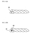
- the structure of stranding three cores enables providing an allowance for thermal contraction occurring during the cooling of the cable.
- thermal contraction can be absorbed by a structure in which stranded cable cores are disposed in a snake-like shape, or the strand of the cable cores is loosened, or a spacer is disposed between the cable cores.
- both bipolar transmission and monopole transmission can be implemented.
- the use of the three cores can be selected as desired.
- the respective cores can be used as a positive electrode core, a negative electrode core, and a neutral line core, the neutral line core being used as a spare for the positive electrode core and the negative electrode core.
- a superconducting cable provided with a return-current conductor for each core can be used as a channel for a return current.
- three cores can be cooled at the same time, thereby making it possible to simplify the cooling mechanism. Further, since three cores are stranded, a means for compensating thermal contraction occurring during cooling can be easily provided.
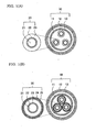
- Figure 1(A) is a sectional view illustrating a superconducting cable without a return-current conductor according to the present invention.
- Figure 1(B) is a sectional view illustrating a superconducting cable with a return-current conductor according to the present invention.
- the thermal insulation pipe 10 is a double pipe structure formed by an inner pipe 11 and an outer pipe 12.
- a vacuum thermal insulation layer 13 is disposed between the inner pipe 11 and the outer pipe 12.
- a laminated body formed of a plastic net and a metal foil, i.e., so-called "super insulation” is disposed within the vacuum thermal insulation layer.
- a space formed between the inner side of the inner pipe 11 and the core 20 serves as a channel for a coolant, such as liquid nitrogen.
- an anticorrosion layer may be formed with a material such as polyvinyl chloride around the outer periphery of the thermal insulation pipe.
- each core 20 housed in the thermal insulation pipe is formed of, sequentially from the center, a former 21, a superconducting cable conductor 22, and an electrical insulating layer 23. If the voltage applied to the conductor is high, it is preferable that a ground layer (not shown) grounded at the outer side of the insulating layer 23 be provided. Further, as shown in Fig. 1(B), a return-current conductor 24 and a protective layer 25 may be provided at the outer side of the electrical insulating layer 23.
- a solid former made of stranded metal wires, or a hollow former made of a metal pipe can be used as the former 21.
- Stranded copper wires may be used as the solid former, for example. If a hollow former is used, the inside of the former can be used as a channel for a coolant.
- High-temperature oxide superconductors of a tape-like shape such as Bi-based superconductor each covered with a silver sheath, can be suitably used for the superconducting cable conductor 22.
- the tape wires are wound on the former in multilayers so as to form a conductor. It is preferable that the superconducting tapes be wound so as to form an even number of layers, and the winding direction of the tapes be opposite alternately in layers.
- Such multilayer structure enables decrease in the leakage of a magnetic flux to the exterior.
- the electrical insulating layer 23 is formed on the outer periphery of the above-described superconducting cable conductor 22.
- the electrical insulating layer 23 can be formed by winding kraft paper or semi-synthetic insulating paper (for example, PPLP (registered trademark) produced by Sumitomo Electric Industries, Ltd.). In the cable of the present invention, it is not necessary to provide a shielding layer for magnetic shielding at the outer side of the electrical insulating layer 23.
- a shielding layer is formed by winding superconducting tapes on the outer side of an electrical insulating layer, and the generation of a magnetic field leaking to the exterior is cancelled by inducing into the shielding layer a current whose magnitude is substantially the same as that of the superconducting cable conductor and whose direction is opposite to the direction of the current in the superconducting cable conductor.
- the generation of an external magnetic field is suppressed by the winding structure of superconducting tapes forming the conductor itself, it is unnecessary to provide a shielding layer for magnetic shielding using superconducting tapes.
- a ground layer which is used for grounding, be provided at the outer side of the electrical insulating layer 23.
- This ground layer prevents a voltage from being applied to a coolant existing between the thermal insulation pipe and the electric insulating layer.
- the ground layer can be formed by winding, for example, a metal tape or another conductive or semiconductive tape.
- the return-current conductor 24 is required.
- a reciprocating channel for a current is required, and a return-current conductor is provided as a channel for a return current in monopole transmission in which three cores are used independently.
- the return-current conductor 24 is formed by superconducting wires similar to those for the conductor 22 with superconducting wires, and has a current capacity comparable to that of the conductor 22 with superconducting wires.
- the protective layer 25 formed by an insulating material must be provided at the outer side of the return-current conductor 24. The protective layer 25 mechanically protects the return-current conductor 24, and also prevents shunting of a return current to the thermal insulation pipe 10 by insulating the return current conductor 24 from the thermal insulation pipe (inner pipe 11).
- the structure of stranding three cores enables providing a means for achieving compensation of thermal contraction occurring during the cooling of the cable.
- thermal contraction can be absorbed by a structure in which stranded cable cores are disposed in a snake-like form, or the strand of the cable cores is loosened, or a spacer is disposed between the cores.
- the technique disclosed in Japanese Patent Application Publication No. 1-309212 can be applied for disposing stranded cable cores in a snake-like form.
- projections are formed in the thermal insulation pipe such that the stranded cores inserted thereinto are housed in a snake-like form.
- Thermal contraction can also be absorbed by the structure in which the strand of cable cores is loosened.
- the strand becomes tightened to such a degree as to eliminate the loosened portion, thereby absorbing the thermal contraction and preventing a large amount of tension from being imposed on the cores.
- the technique disclosed in Japanese Patent Application Publication No. 9-134624 can be used as a method for loosening the strand of cores.
- stranded cores are housed in a thermal insulation pipe, and a coolant is supplied to the pipe so as to contract the cores.
- the cores are disposed substantially linearly from one end to the other end of the thermal insulation pipe, and the two ends of the thermal insulation pipe are covered with caps. Thereafter, the temperature of the thermal insulation pipe is increased so that the cores are meandered in a snake-like form in the thermal insulation pipe, thereby loosening the strand.
- Another means for loosening the strand of cores is the technique disclosed in Japanese Patent Application Publication No. 2001-67950. According to this technique, in which a process of covering the outer periphery of the cores with a thermal insulation pipe (inner pipe) is provided, the speed of the covering step or a downstream step thereof is set to be lower than the speed at which the cores are supplied, thereby the strand of the cores is loosened such that thermal contraction can be absorbed during cooling.
- the technique disclosed in Japanese Patent Application Publication No. 9-134620 can be used for interposing a spacer between cores.
- cores are stranded by interposing a spacer 30 at the center of the cores.
- the cores 20 are maintained by the spacer 30 in a stranded state similar to that in which they are loosened.
- the cores 20 are contracted, as well as the spacer 30.
- the stranded cores 20 are tightened, thereby absorbing thermal contraction.
- both bipolar transmission and monopole transmission can be implemented. Regardless of whether bipolar transmission or monopole transmission is performed, the use of the respective three cores can be selected as desired.
- each core is formed of, sequentially from the center, a former, a conductor with superconducting wires, and an electrical insulating layer. It is preferable, however, that a ground layer be provided at the outer periphery of the electrical insulating layer. Generally, a thermal insulation pipe is grounded.
- a coolant which is present between the thermal insulation pipe and the electrical insulating layer carries a potential distribution, as in the electrical insulating layer of each core.
- the transmission voltage is high
- the insulation performance of the coolant may run into a problem.
- a ground layer at the periphery of the electrical insulating layer of each core, the application of the voltage to the coolant can be prevented.
- a current does not flow in the ground layer.
- a superconductor need not be used as the material for the ground layer, and a regular conductor, such as a metal, can be used.
- the three cores are used as a positive electrode core 20A, a neutral line core 20B, and a negative electrode core 20C.
- a power source 40 is disposed between the positive electrode core 20A and the neutral line core 20B and between the neutral line core 20B and the negative electrode core 20C.
- the neutral line core 20B is grounded. Such grounding may be done only at one end or both ends of the neutral line core 20B.
- transmission is performed by using the positive electrode core 20A and the negative electrode core 20C. In this case, the transmission capacity results in 2 ⁇ I ⁇ V, where I indicates the transmission current, and V indicates the transmission voltage. In the event of a failure in either of the positive electrode core 20A or the negative electrode core 20C, a current flows in the neutral line core 20B.
- one cable has a three-core structure, and the three cores can be cooled at the same time, thereby simplifying the cooling system.
- the superconducting cable line of the present invention performing monopole transmission is shown in Fig. 4.
- the line is formed by using a cable having the same structure as that of the superconducting cable shown in Fig. 1(B). That is, each core is formed of, sequentially from the center, a former, a superconducting cable conductor, an electrical insulating layer, a return-current conductor, and a protective layer.
- Power sources 40A through 40C are connected to the cores 20A through 20C, respectively, so as to supply power.
- the specifications of the power sources 40A through 40C may be the same or may be different.
- a return-current conductor 24 for each of the cores 20A through 20C is formed of superconducting wires similar to those used for the superconducting cable conductor, and has a transmission capacity comparable to that of the superconducting cable.
- the return-current conductor 24 is grounded.
- the return-current conductor 24 is used as a channel for a return current, in which case, the leakage of a magnetic flux to the exterior of the cores can be canceled. While in Fig. 4, only part of the return-current conductor 24 is schematically shown in the longitudinal direction, in practice, the return-current conductor 24 is disposed in the entire longitudinal direction.
- each core can be used for transmission. Accordingly, the transmission capacity results in 3 x I x V, which is 1.5 times as large as the transmission capacity of a line used in the bipolar transmission system.
- the transmission capacity of the cores 20A through 20C may be the same or may be different. That is, since transmission is performed independently by each core in the monopole transmission system, the transmission capacity of the cores 20A through 20C need not be the same, and the cores 20A through 20C serve as transmission lines for a maximum of three power sources.
- the conductor structures of the cores 20A through 20C can be different according to the load.
- the transmission capacities of the cores 20A through 20C may be differentiated as 2000A, 1500A, and 1000A, respectively.
- the specifications of the cores 20A through 20C can be varied by changing, for example, the performance, the sectional area, or the number of superconducting tapes that constitute the conductor or the return-current conductor.
- a cable can be designed in accordance with the power of the load, thereby reducing the total cost of the line.
- a plurality of cores can be cooled at the same time.
- the cooling system can be simplified, the cooling efficiency can be enhanced, and the cost of the cable itself can be reduced compared to a system in which each of single-core cables is cooled independently.
Landscapes
- Superconductors And Manufacturing Methods Therefor (AREA)
Applications Claiming Priority (5)
| Application Number | Priority Date | Filing Date | Title |
|---|---|---|---|
| JP2001384979 | 2001-12-18 | ||
| JP2001384979 | 2001-12-18 | ||
| JP2002360189A JP4482851B2 (ja) | 2001-12-18 | 2002-12-12 | 直流超電導ケーブル |
| JP2002360189 | 2002-12-12 | ||
| PCT/JP2002/013166 WO2003052774A1 (en) | 2001-12-18 | 2002-12-17 | Dc superconducting cable |
Publications (2)
| Publication Number | Publication Date |
|---|---|
| EP1455367A1 true EP1455367A1 (de) | 2004-09-08 |
| EP1455367A4 EP1455367A4 (de) | 2006-12-20 |
Family
ID=26625120
Family Applications (1)
| Application Number | Title | Priority Date | Filing Date |
|---|---|---|---|
| EP02786109A Withdrawn EP1455367A4 (de) | 2001-12-18 | 2002-12-17 | Gleichstrom-supraleitendes kabel |
Country Status (5)
| Country | Link |
|---|---|
| US (1) | US7238887B2 (de) |
| EP (1) | EP1455367A4 (de) |
| JP (1) | JP4482851B2 (de) |
| KR (1) | KR100874605B1 (de) |
| WO (1) | WO2003052774A1 (de) |
Cited By (3)
| Publication number | Priority date | Publication date | Assignee | Title |
|---|---|---|---|---|
| CN103578648A (zh) * | 2012-07-25 | 2014-02-12 | 尼克桑斯公司 | 具有三个超导性的相线导体的装置 |
| WO2018197427A1 (de) * | 2017-04-25 | 2018-11-01 | Siemens Aktiengesellschaft | Vorrichtung und verfahren zur gleichstromübertragung mit hoher nennleistung |
| US20220084725A1 (en) * | 2018-09-07 | 2022-03-17 | Tokamak Energy Ltd | Flexible hts current leads |
Families Citing this family (22)
| Publication number | Priority date | Publication date | Assignee | Title |
|---|---|---|---|---|
| US7608785B2 (en) * | 2004-04-27 | 2009-10-27 | Superpower, Inc. | System for transmitting current including magnetically decoupled superconducting conductors |
| JP4766224B2 (ja) * | 2004-05-21 | 2011-09-07 | 住友電気工業株式会社 | 直流用超電導ケーブルを用いた直流送電方法 |
| JP4716248B2 (ja) * | 2004-05-21 | 2011-07-06 | 住友電気工業株式会社 | 超電導ケーブル |
| JP5423692B2 (ja) * | 2004-05-21 | 2014-02-19 | 住友電気工業株式会社 | 超電導ケーブル |
| JP4730583B2 (ja) | 2004-12-01 | 2011-07-20 | 住友電気工業株式会社 | 超電導ケーブル線路 |
| JP4843937B2 (ja) | 2004-12-02 | 2011-12-21 | 住友電気工業株式会社 | 超電導ケーブル |
| JP4609638B2 (ja) | 2004-12-06 | 2011-01-12 | 住友電気工業株式会社 | 直流超電導ケーブルの設計システム |
| JP4609704B2 (ja) | 2005-01-12 | 2011-01-12 | 住友電気工業株式会社 | 超電導ケーブルの接続部の組み立て方法 |
| RU2388090C2 (ru) * | 2005-03-14 | 2010-04-27 | Сумитомо Электрик Индастриз, Лтд. | Сверхпроводящий кабель и система передачи постоянного тока, содержащая этот сверхпроводящий кабель |
| US7943852B2 (en) | 2005-03-14 | 2011-05-17 | Sumitomo Electric Industries, Ltd. | Superconducting cable |
| DK1720176T3 (da) * | 2005-05-06 | 2007-03-05 | Nexans | Superlederkabel |
| KR100706494B1 (ko) * | 2006-01-20 | 2007-04-10 | 엘에스전선 주식회사 | 초전도 케이블 |
| KR100772822B1 (ko) * | 2007-01-04 | 2007-11-01 | 엘에스전선 주식회사 | 초전도 케이블 코어의 연합 꼬임구조 |
| EP2017856B1 (de) * | 2007-07-17 | 2014-09-03 | Nexans | Supraleitfähiges elektrisches Kabel |
| EP2144258B1 (de) * | 2008-07-10 | 2011-10-26 | Bruker HTS GmbH | Kryostat für ein elektrisches Stromversorgungsgerät |
| TWM351419U (en) * | 2008-10-13 | 2009-02-21 | Quanta Comp Inc | Electronic device and navigation device |
| JP2009070833A (ja) * | 2009-01-07 | 2009-04-02 | Sumitomo Electric Ind Ltd | 超電導ケーブルの端末構造の製造方法 |
| JP2011091057A (ja) * | 2011-01-13 | 2011-05-06 | Sumitomo Electric Ind Ltd | 直流用超電導ケーブル |
| US8938278B2 (en) | 2011-02-18 | 2015-01-20 | The Regents Of The University Of Colorado | Superconducting cables and methods of making the same |
| DK2551859T3 (da) * | 2011-07-28 | 2014-11-03 | Nexans | Anordning med et superledende elektrisk jævnstrømskabelsystem |
| WO2015018418A1 (en) | 2013-08-09 | 2015-02-12 | Vestas Wind Systems A/S | Electricity transmission |
| CN111128469A (zh) * | 2020-01-09 | 2020-05-08 | 上海电缆研究所有限公司 | 带回流通道的超导电缆 |
Family Cites Families (13)
| Publication number | Priority date | Publication date | Assignee | Title |
|---|---|---|---|---|
| JPH01309212A (ja) | 1988-06-06 | 1989-12-13 | Hitachi Cable Ltd | 超電導ケーブルの冷却方法 |
| US6262375B1 (en) * | 1992-09-24 | 2001-07-17 | Electric Power Research Institute, Inc. | Room temperature dielectric HTSC cable |
| JPH07169343A (ja) * | 1993-10-21 | 1995-07-04 | Sumitomo Electric Ind Ltd | 超電導ケーブル導体 |
| JP3568659B2 (ja) | 1995-11-08 | 2004-09-22 | 住友電気工業株式会社 | 超電導ケーブル |
| JP3512927B2 (ja) | 1995-11-08 | 2004-03-31 | 住友電気工業株式会社 | 超電導ケーブルの製造方法 |
| IT1277740B1 (it) | 1995-12-28 | 1997-11-12 | Pirelli Cavi S P A Ora Pirelli | Cavo superconduttore per alta potenza |
| JP3792861B2 (ja) | 1997-10-09 | 2006-07-05 | 株式会社フジクラ | 中性線複合直流電力用ケーブル |
| EP1188167B1 (de) * | 1999-06-02 | 2005-11-30 | Pirelli & C. S.p.A. | Verfahren zum verbinden von hochtemperatursupraleitenden komponenten in einem supraleitenden kabel mit unbedeutender kritischer strom degradation und auf diese weise hergestellte artikel |
| JP4623401B2 (ja) * | 1999-06-22 | 2011-02-02 | 住友電気工業株式会社 | 超電導ケーブルの製造方法 |
| JP4487361B2 (ja) | 2000-01-20 | 2010-06-23 | 住友電気工業株式会社 | 超電導ケーブル |
| JP2002100249A (ja) * | 2000-07-21 | 2002-04-05 | Furukawa Electric Co Ltd:The | 交流用超電導ケーブル |
| JP2002124141A (ja) | 2000-10-13 | 2002-04-26 | Hitachi Cable Ltd | 直流電力ケーブル |
| JP4031204B2 (ja) | 2001-01-15 | 2008-01-09 | 住友電気工業株式会社 | 超電導ケーブルの製造方法 |
-
2002
- 2002-12-12 JP JP2002360189A patent/JP4482851B2/ja not_active Expired - Fee Related
- 2002-12-17 US US10/474,821 patent/US7238887B2/en not_active Expired - Fee Related
- 2002-12-17 KR KR1020037014250A patent/KR100874605B1/ko not_active Expired - Fee Related
- 2002-12-17 WO PCT/JP2002/013166 patent/WO2003052774A1/ja not_active Ceased
- 2002-12-17 EP EP02786109A patent/EP1455367A4/de not_active Withdrawn
Cited By (5)
| Publication number | Priority date | Publication date | Assignee | Title |
|---|---|---|---|---|
| CN103578648A (zh) * | 2012-07-25 | 2014-02-12 | 尼克桑斯公司 | 具有三个超导性的相线导体的装置 |
| CN103578648B (zh) * | 2012-07-25 | 2017-05-10 | 尼克桑斯公司 | 具有三个超导性的相线导体的装置 |
| WO2018197427A1 (de) * | 2017-04-25 | 2018-11-01 | Siemens Aktiengesellschaft | Vorrichtung und verfahren zur gleichstromübertragung mit hoher nennleistung |
| US20220084725A1 (en) * | 2018-09-07 | 2022-03-17 | Tokamak Energy Ltd | Flexible hts current leads |
| US12131837B2 (en) * | 2018-09-07 | 2024-10-29 | Tokamak Energy Ltd | Flexible HTS current leads with stabiliser and terminal block |
Also Published As
| Publication number | Publication date |
|---|---|
| JP2003249130A (ja) | 2003-09-05 |
| US20040216915A1 (en) | 2004-11-04 |
| US7238887B2 (en) | 2007-07-03 |
| WO2003052774A1 (en) | 2003-06-26 |
| KR100874605B1 (ko) | 2008-12-17 |
| JP4482851B2 (ja) | 2010-06-16 |
| KR20040062445A (ko) | 2004-07-07 |
| EP1455367A4 (de) | 2006-12-20 |
Similar Documents
| Publication | Publication Date | Title |
|---|---|---|
| US7238887B2 (en) | DC superconducting cable | |
| US7598458B2 (en) | Super-conductive cable | |
| US5952614A (en) | A.C. cable with stranded electrical conductors | |
| EP1034581B1 (de) | Energieinduktionsvorrichtung | |
| CA2529439C (en) | Joint for superconducting cable | |
| MXPA01008327A (es) | Un cable, un metodo para construir un cable y uso de un cable. | |
| CA2468216C (en) | Phase split structure of multiphase superconducting cable | |
| US7633014B2 (en) | Superconductor cable | |
| US7943852B2 (en) | Superconducting cable | |
| CN101142636B (zh) | 超导电缆和包含该超导电缆的dc传输系统 | |
| JP3877057B2 (ja) | 高温超電導ケーブル | |
| KR101148574B1 (ko) | 초전도 케이블 | |
| JP4716248B2 (ja) | 超電導ケーブル | |
| KR102621367B1 (ko) | 초전도 케이블 | |
| JP5423692B2 (ja) | 超電導ケーブル | |
| HK1115223B (en) | Superconductive cable and dc transmission system incoporating the superconductive cable | |
| HK1115222B (en) | Superconducting cable |
Legal Events
| Date | Code | Title | Description |
|---|---|---|---|
| PUAI | Public reference made under article 153(3) epc to a published international application that has entered the european phase |
Free format text: ORIGINAL CODE: 0009012 |
|
| 17P | Request for examination filed |
Effective date: 20031013 |
|
| AK | Designated contracting states |
Kind code of ref document: A1 Designated state(s): AT BE BG CH CY CZ DE DK EE ES FI FR GB GR IE IT LI LU MC NL PT SE SI SK TR |
|
| A4 | Supplementary search report drawn up and despatched |
Effective date: 20061122 |
|
| 17Q | First examination report despatched |
Effective date: 20130604 |
|
| STAA | Information on the status of an ep patent application or granted ep patent |
Free format text: STATUS: THE APPLICATION HAS BEEN WITHDRAWN |
|
| 18W | Application withdrawn |
Effective date: 20151215 |