EP1455423B1 - Steckverbinder mit einem Kurzschlusskontakt - Google Patents
Steckverbinder mit einem Kurzschlusskontakt Download PDFInfo
- Publication number
- EP1455423B1 EP1455423B1 EP03003432A EP03003432A EP1455423B1 EP 1455423 B1 EP1455423 B1 EP 1455423B1 EP 03003432 A EP03003432 A EP 03003432A EP 03003432 A EP03003432 A EP 03003432A EP 1455423 B1 EP1455423 B1 EP 1455423B1
- Authority
- EP
- European Patent Office
- Prior art keywords
- plug connector
- accordance
- short circuit
- snap
- security element
- Prior art date
- Legal status (The legal status is an assumption and is not a legal conclusion. Google has not performed a legal analysis and makes no representation as to the accuracy of the status listed.)
- Expired - Lifetime
Links
- 230000000295 complement effect Effects 0.000 claims description 14
- 238000003780 insertion Methods 0.000 description 20
- 230000037431 insertion Effects 0.000 description 20
- 210000002105 tongue Anatomy 0.000 description 19
- 230000013011 mating Effects 0.000 description 18
- 230000008878 coupling Effects 0.000 description 10
- 238000010168 coupling process Methods 0.000 description 10
- 238000005859 coupling reaction Methods 0.000 description 10
- 239000002184 metal Substances 0.000 description 6
- 238000001514 detection method Methods 0.000 description 5
- 238000000926 separation method Methods 0.000 description 5
- 238000012549 training Methods 0.000 description 5
- 230000008859 change Effects 0.000 description 4
- 230000012447 hatching Effects 0.000 description 4
- 238000002347 injection Methods 0.000 description 3
- 239000007924 injection Substances 0.000 description 3
- 230000000903 blocking effect Effects 0.000 description 2
- 230000014759 maintenance of location Effects 0.000 description 2
- 230000000284 resting effect Effects 0.000 description 2
- 238000010276 construction Methods 0.000 description 1
- 230000006378 damage Effects 0.000 description 1
- 238000013461 design Methods 0.000 description 1
- 238000011161 development Methods 0.000 description 1
- 230000018109 developmental process Effects 0.000 description 1
- 239000012777 electrically insulating material Substances 0.000 description 1
- 230000002996 emotional effect Effects 0.000 description 1
- 230000006698 induction Effects 0.000 description 1
- 238000009434 installation Methods 0.000 description 1
- 238000004519 manufacturing process Methods 0.000 description 1
- 230000000750 progressive effect Effects 0.000 description 1
- 238000012360 testing method Methods 0.000 description 1
- 238000012546 transfer Methods 0.000 description 1
- 230000007704 transition Effects 0.000 description 1
- 230000001960 triggered effect Effects 0.000 description 1
Images


Classifications
-
- H—ELECTRICITY
- H01—ELECTRIC ELEMENTS
- H01R—ELECTRICALLY-CONDUCTIVE CONNECTIONS; STRUCTURAL ASSOCIATIONS OF A PLURALITY OF MUTUALLY-INSULATED ELECTRICAL CONNECTING ELEMENTS; COUPLING DEVICES; CURRENT COLLECTORS
- H01R13/00—Details of coupling devices of the kinds covered by groups H01R12/70 or H01R24/00 - H01R33/00
- H01R13/64—Means for preventing incorrect coupling
- H01R13/641—Means for preventing incorrect coupling by indicating incorrect coupling; by indicating correct or full engagement
-
- H—ELECTRICITY
- H01—ELECTRIC ELEMENTS
- H01R—ELECTRICALLY-CONDUCTIVE CONNECTIONS; STRUCTURAL ASSOCIATIONS OF A PLURALITY OF MUTUALLY-INSULATED ELECTRICAL CONNECTING ELEMENTS; COUPLING DEVICES; CURRENT COLLECTORS
- H01R13/00—Details of coupling devices of the kinds covered by groups H01R12/70 or H01R24/00 - H01R33/00
- H01R13/66—Structural association with built-in electrical component
- H01R13/70—Structural association with built-in electrical component with built-in switch
- H01R13/703—Structural association with built-in electrical component with built-in switch operated by engagement or disengagement of coupling parts, e.g. dual-continuity coupling part
- H01R13/7031—Shorting, shunting or bussing of different terminals interrupted or effected on engagement of coupling part, e.g. for ESD protection, line continuity
- H01R13/7032—Shorting, shunting or bussing of different terminals interrupted or effected on engagement of coupling part, e.g. for ESD protection, line continuity making use of a separate bridging element directly cooperating with the terminals
Definitions
- the present invention relates to a connector device.
- Connector devices with two mating connectors are used to make ends of two cables or harnesses simply by plugging together electrically and mechanically with each other connect to.
- Connector devices are used, for example, a at least two-core cable from a triggering device for an airbag and a corresponding two-wire cable to a gas generator of Airbags connect.
- a gas generator unintentionally before being connected to the tripping device during transport or during the assembly between the wires possibly occurring potential differences or voltages are triggered
- connector devices used in which the leading to the gas generator two-wire cable connected connector a shorting element contains, by means of which two contact elements connected to the wires be shorted in the connector when the connector the connector device are not mated.
- the Mating or pushing the connector during assembly of the Airbags in a motor vehicle is then canceled the short circuit.
- Such connector devices may further include a security device which is operable only when the connectors are fully mated, and with the connectors in the mated state against accidental release of the connector can be secured.
- the safety device is doing operated by a person who makes the plug connection. Another Checking the plug connection does not take place.
- EP-A-0 902 506 discloses a connector having a female connector and a male connector, a connection detection element and a short-circuit breaking element.
- the plug connection is made by inserting the and mating connector plugged together and then successively the connection detection element and the short-circuit interruption element to be assembled.
- a mated condition of Connector is detected depending on whether the connection detection element mounted on the female connector can or not. If the short-circuit interruption element mounted after a correct mating of the connectors becomes a short circuit of contacts to be inserted in the housing interrupted the inserted connector. Because the connection detection element and the short circuit breaker are separate components that can be mounted independently of each other or can be dismantled, both the connection detection and the short-circuit interruption are carried out correctly.
- EP-A-1081804 is an electrical connector with a short-circuiting device described, the housing has a front mating end with a Having opening for receiving a complementary connector.
- the Opening leads into an inner chamber.
- Connection elements have contact portions in the chamber, which with corresponding connection elements of the complementary connector in Intervention can be brought.
- a shorting element has a retention section for securing the shorting element in the housing near the Opening up.
- An inclined portion extends in the rearward direction from the retention section into the chamber to coincide with the complementary Connectors can be engaged.
- a contact section stands from the inclined portion of the retaining portion spaced apart to at least with a pair of the connection elements in the absence of the complementary connector engaged to be able to.
- the present invention is based on the object, a connector device to provide, in the construction of a potential difference or voltage between two contact elements of a connector the connector device in the unmated state is preventable and that allows to easily check if the connectors assume a completely mated condition.
- the connector device comprises a first Connector body, a mating with the first connector body second connector body, in or on the at least partially at least two contact elements and a short-circuit element are arranged from a short-circuited state in which the Shorting element short circuits the two contact elements, in one Disconnected state in which the short circuit of the contact elements canceled is, are displaceable, and one in and / or at the first and / or second Connector body arranged securing device with a movable securing element, which from a starting position in a Fuse position is movable when the connector body completely and not just partially plugged together, and by means of that the connector body in the fully assembled position are securable, wherein by movement of the fuse element at complete assembled connector bodies, the contact elements and the short-circuit element from the short-circuited state to the disconnected state are displaceable.
- the first connector body may be to the at least two contact elements the second connector body complementary contact elements and thus form a first connector.
- the second Connector body forms with the contact elements arranged therein and the shorting element a second connector.
- the first Connector body or the first connector is connected to the second Connector body in a through the connector body and / or the position of the contact elements can be plugged together in the given insertion direction, whereby on the one hand a mechanical connection between with connected to the connector bodies or the contact elements therein Cables and an electrical connection can be produced.
- at the contact elements may be any contact elements, in particular in corresponding channels along the plugging direction can be inserted into the connector body.
- the safety device also known in English as "CPA" (connector position assurance) serves to ensure that that the connector body are completely assembled.
- the Securing device is in and / or at least one of Connector body, preferably both, arranged and has a movable securing element, by an operator in the Assembly is to be operated.
- the securing device can be designed such that the movable Fuse element only with fully assembled connector bodies, but not with only partially assembled connector bodies, from a relative at least one of the connector body given starting position in a given also relative to this Fuse position is movable. Otherwise, the movement may be through Interference with one of the connector body be hampered.
- the securing device can furthermore be designed so that the connector bodies not by train, vibrations or others Forces can unintentionally release each other when the fuse element located in the backup position.
- the securing device fulfills both tasks.
- the short-circuit element is provided.
- the arrangement of the two contact elements in the second connector body and the electrically conductive shorting element on it or it can be two Take states.
- a first state the short-circuit state
- the two contact elements are short-circuited by the short-circuit element, so there is no potential difference or voltage between can build the contact elements.
- This condition can be taken be when the fuse element is in the starting position, and the connector body not, partially or completely plugged together are. From this short circuit condition are the contact elements in the second connector body and the shorting element in the second state, the disconnected state, displaceable, in which the short circuit the contact elements is canceled.
- the contact elements can now take over their normal function and electrically from each other each separate electrical connections to corresponding complementary Form contact elements in the first connector.
- the short-circuit state there is a transition from the short-circuit state to the disconnected state not only by mating the connector body but it is in addition the movement of the Fuse element from the initial position in the backup position necessary, a corresponding change in the state of the contact elements effected in the second connector body and the short-circuit element.
- the securing element preferably with at least one of the contact elements and / or the short-circuit element at least be mechanically coupled near the securing position, wherein a Movement of the fuse element directly or indirectly into a change of the state can be implemented.
- the movement of the At least in the vicinity of the backup position as possible directly on at least one of the contact elements and / or the Short circuit element transferred to a change of state too cause.
- the connector device according to the invention is characterized through a very simple structure.
- Canceling the short circuit condition is basically before reaching the backup situation possible.
- the separation state only permanently achievable when the fuse element in the backup position located. Under permanent is understood here that the Separation state for at least one minute, but preferably hours or days is achievable.
- the connector device be formed accordingly.
- the Contact elements and the short-circuit element when plugged together Connector bodies are only in the disconnected state, if the Securing element in the backup position is. It is not yet in the backup position, so that still the short-circuit condition exists.
- Such a connector device can be a particularly simple Have structure.
- a resilient Element is provided, which during a movement of the securing element can be tensioned in the backup position, and by means of which Securing element from a position between the backup position and the Starting position in which the short-circuit state is canceled, at least as far as is movable in the direction of the initial position that the short-circuit state is reached.
- the resilient element one of the connector body or on the fuse element so be formed such that the securing element in the direction of the starting position is moved and by appropriate training of the two contact elements in the second connector body and / or the shorting element and / or with the contact elements and / or the short-circuit element at least partially coupled fuse element of Disconnected state is canceled.
- the securing element and at least one of the connector body complementary locking elements by means of which the securing element in the securing position is latched. It is sufficient that the locking a movement prevented only in the direction of the initial position.
- This can be a backup the fuse element in the backup position, in particular in the case of the embodiment described in the previous paragraph an automatic movement of the securing element in the direction the initial position and an associated change in the short-circuit state can be prevented.
- the short-circuit element at least one having resilient contact portion which in the short-circuited state one of the contact elements rests and by movement of the securing element wegbewegbar in the backup position of the contact element is.
- the short-circuit element has two resilient Contact sections, of which one on each of the Contact elements rests. This will on the one hand a very good contact between the short-circuit element and the contact element achieved in the short circuit condition, with vibration or temperature changes little or no impact on the contact. To the another is the contact between the shorting element and the Contact element very easy by moving the resilient contact section canceled.
- the contact element has a restoring force on the securing element directly or indirectly, if not yet Has reached safety position.
- contact elements conventional contact elements used, which is the manufacture of the connector device simplified.
- one of the contact elements having a resilient contact portion in the short-circuited state rests on the short-circuit element and by movement of the Fuse element in the backup position of the short-circuit element is movable away.
- the short-circuit element can by a simple metal part, for example a short metal pin or a metal plate, be given while a corresponding resilient tongue on at least one of Contact elements may be formed. Because the contact elements are common anyway formed of a resilient metal to by training resilient tongues a Warverriegelung the contact elements in the Can allow connector body, so the number of one resilient metal parts to be kept low.
- the securing element has a tongue, which by movement of the fuse element in the backup position between the resilient Contact section and the contact element or the short-circuit element is movable.
- the tongue is particularly preferably wedge-shaped formed so that the resilient contact portion and the contact element or the short-circuit element with progressive movement of the Fuse element can be pushed further apart.
- the Tongue is made of an electrically insulating material or coated with such.
- the securing element on the first Connector body is held.
- the first connector body on a corresponding leadership, by means of which the fuse element between the starting position and the backup position is feasible.
- the securing element substantially along a plug-in direction in which the connector body can be plugged together are, is displaceable.
- the connector body, where the fuse element is held a corresponding have linear guide.
- the leadership and the securing element designed so that the securing element captive is held on the connector. In essence, by the leadership In the plugging direction, such a connector device can be very easy to use even in a small space, because both the mating as well as the fuse along the same spatial direction can be done.
- the connector bodies are complementary to each other Have snap or locking elements, by means of which the connector body in the fully mated condition with each other are connectable.
- Particularly preferred are the preparation and / or the existence of the corresponding snap or locking connection securable by the securing device. That means that Securing element only when produced snap or locking connection in the securing position is movable and / or that a release of the snap-action or latching connection by the securing element located in the securing position is preventable.
- the snap or locking connection can Take tensile forces, in particular along the direction of insertion and so already prevent loosening of the connector at not too great forces.
- Locking elements are particularly preferably used, so that an independent Release the connector only with destruction of the locking elements is possible, but when mating only the locking resistance must be overcome.
- one of the complementary Snap-action or latching elements for producing the snap-in or latching connection preferably resilient, deflectable.
- the deflection from a Resting position may in particular by a deformation of the snap or latching element can be obtained.
- the direction of the deflection runs preferably transversely, but not necessarily orthogonal to the direction of movement of the fuse element, resulting in a simpler training the snap or locking elements is made possible.
- deflectable Snap-on or locking elements make it possible with little effort make a snap or locking connection, but in particular to withstand relatively large tensile forces at locking connections can.
- one of the snap or locking elements by a resilient latching arm with a trained at its free end Latch hook or a resilient latching tongue with a recess or Opening in which a locking projection or block is latched, be given.
- one of the snap-action or latching elements has a guide slope, by means of which the snap or locking elements relative to each other are feasible, so by plugging the connector body the deflectable snap or locking element by means of the guide slope is deflectable.
- the deflectable snap or latching element in one Trajectory of the fuse element between the starting position and the securing position is arranged, and / or that the securing element in the backup position a deflection of the deflectable snap or Restricted locking element.
- the limitation is such that a release the snap or locking connection is prevented.
- the safety device together with the deflectable snap or locking element to train accordingly. The safety device then serves only to the occurrence or existence of the locking connection to to back up.
- the safety device does not necessarily need large Forces, for example, tensile forces to record. Especially, if both functions are fulfilled, at the same time results in a good mechanical Connection of the connector body in the fully assembled Condition and reliable checking and securing the Location of the connector body.
- the securing element by plugging together the connector body is movable to the starting position. This is in the basically first step of the mating the fuse element automatically placed in a position that an implementation of the second step, namely the operation the safety device with mated connector bodies, allows. This allows a particularly efficient installation.
- the fuse element can in any way to be moved.
- the securing element by the deflection of the deflectable snap or locking element is movable in the direction of the initial position.
- This can in particular a positive guide be provided by means of which the deflection movement the deflectable snap or locking element in a corresponding Movement of the fuse element is implemented. In this way needs up to the forced operation no further device provided to be, which causes the movement.
- the securing element on the deflectable snap or latching element attached to one of the connector body is held, is guided, and that on the other connector body a projection is provided, which is a movement of the securing element relative to the connector body to which it is guided is, when mating the connector body and during deflection limited the deflectable snap or locking element.
- the Deflection is the securing element in the area of the projection out, which only forms a stop at the deflection, the fuse element stationary relative to the other connector body, while the connector body to which the fuse element is guided, relative to the other connector body and the fuse element emotional. In this way, structurally particularly simple achieved a movement of the fuse element in the starting position become.
- another stop in the direction the deflection is provided under the fuse element at Movement is movable in the backup position and by means of a Deflection of the deflectable snap or latching element and the it guided fuse element in the backup position can be limited.
- a release of the snap or locking connection by an accidental or caused by vibration deflecting the deflectable snap or locking element can be prevented.
- the further stop is preferably held on the connector body, where the fuse element is not held.
- the stop and the further stop be realized by a strap. This can be a mechanical Form protection of the fuse element.
- the connector device according to the invention is particularly suitable for connecting lines between a gas generator and a Tripping device of an airbag in a motor vehicle.
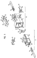
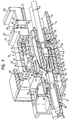
- a connector device in a preferred embodiment of the invention, a first connector 10 and a second connector 12.
- the first connector 10 includes a connector body 14, two female contact elements 18, with which two with a triggering device not shown in the figures for an airbag connectable cables 16 are connected, and a first Second locking body 20 for securing the socket contact elements 18 in the first connector body 14. Furthermore, a fuse element 22 held on the first connector body 14.
- the second Connector 12 has a second connector body 24, two arranged therein contact elements 26, with which two on with a Gas generator of an airbag connectable cables 28 are connected, a second second locking body 30 for the second locking of the contact elements 26 in the second connector body 24 and one in the second connector body 24 plug-in short-circuit element 32nd
- the plastic injection molded part executed first connector body 14 in an elongated first Housing part 34 a contact element receptacle 36 with two first channels 38, a formed by a portion of the first housing part 34, the Contact element receptacle 36 partially enclosing connector receptacle 40 and formed on the first housing part 34, in Longitudinal direction of the housing part 34 extending locking element 42 in the form a latching tongue on.
- the connector receptacle 40 serves to receive a corresponding Area of the second connector 12, the mating is guided on the connector receptacle 40 in a plug-in direction.
- the connector receptacle 40 is at one in the insertion direction of the first Connector body 14 lying side of the first connector body 14 trained circumferentially and then goes in a to the locking element 42 opening U-shaped section over, in a given Distance from the connector receptacle 40 is arranged.
- first channels 38 formed in the socket contact elements 18 inserted with the cables 16 held thereon are.
- a chamber 44 extends to Receiving the first secondary locking body 20.
- the female contact elements 18 are in the channels 38 by means of resilient Motherverriegelungszonne 46 held behind corresponding projections.
- the second locking body 20 has a forked portion 48 and a in at a right angle thereto formed holding portion 50 and is so designed that when inserting the second locking body 20 in the Chamber 44 of the fork-shaped portion 48 behind the socket contact elements 18 engages while the holding section 50 behind corresponding Ledge 52 on the outside of the first connector body 14 latched is.
- the latching element 42 extending along the plug-in direction is open the upper side in the figures of the first connector body 14th arranged and resiliently deflectable in a direction transverse to the insertion direction.
- the free end of the locking tongue formed as a locking element 42nd is partially within the circumferential portion of the connector receptacle 40 arranged. It has an extending in the insertion direction Latching opening 53 on.
- the free end of the locking element 42 is at the End face formed in the shape of a blunt wedge, so that the Thickness of the locking element 42 tapers in the direction in which this too is deflectable.
- the lower bevelled surface forms a first Guide slope 54.
- the locking element 42 further comprises two lateral first locking projections 56.
- a guide and holding block 58 is provided, which is wider than the locking element 42 and the underside thereof aligned with the underside of the locking element 42.
- the made of an electrically insulating plastic as an injection molded part Securing element 22 comprises an elongated locking portion 60, which has a substantially U-shaped profile, a itself subsequent guide portion 62 and one on the guide portion 62 held actuating tongue 64, which are substantially parallel extends to the locking portion 60.
- the guide portion 62 carries at a region 66 with a U-shaped profile on the free legs of the U held guide plates 72, which are in the opposite direction to Continue the locking portion 60 beyond the area 66 addition.
- Area 66 are also first recesses 68 for forming a Locking connection formed with the first locking projections 56 laterally.
- an actuating bar 70 is arranged.
- the actuating tongue 64 is wedge-shaped at its free end and has at its the locking portion 60 facing in the figures upper side an oblique to the direction of insertion oriented actuating surface 74 on which a parallel to the locking portion 60 extending sliding surface opposite.
- the fuse element 22 is connected to the guide portion 62 on the Locking element 42 of the first connector body 14 linearly movable guided, wherein the area 66 to the locking element 42 and the guide plates 72 under the locking element 42 and the guide and holding block 58 grab.
- the guide and retaining block 58 further defines a Movement of the fuse element 22 against the plugging direction.
- the Actuation tongue 64 slides with the sliding surface on the contact element receiving 40 of the connector body 14, the socket contact elements 18 takes up.
- the fuse element 22 is thus captive the first connector body 14 linearly movable in the insertion direction guided.
- the likewise designed as a plastic injection molded part second connector body 24 includes an elongated second housing portion 76 having an in the connector receptacle 40 of the first connector body 14 in Insertion direction plug-in coupling portion 78, one in the housing part 76 arranged second contact element receptacle 80 for receiving the contact elements 26, one arranged on the coupling portion 78 Bracket 82 and also on the coupling portion 78th arranged locking block 84th
- the second contact element receptacle 80 are two in the longitudinal direction and thus extending in the insertion direction, through the second connector body formed through channels 86, in which the contact elements 26 are inserted with the cables 28 held thereon.
- the Channels 86 are aligned with the corresponding channels 38 in the first connector body 14th
- the channels 86 thereby extend into that of the coupling section 78 enclosed area, making contact tongues to the Socket contact elements 18 complementary contact elements 26 in protrude the area enclosed by the coupling portion 78 and when mating the connector body 14 and 24 into each other are insertable.
- the contact elements 26 have a, not shown in the figures, the usual Warverriegelung on, by corresponding resilient Moverriegelungszonne similar to the Clearverriegelungszonne 46 of the female contact elements 18 and projections may be given in the channels 86.
- an H-shaped opening 88th formed by the second second locking body 30 in the second connector body 24 inserted and there by means of second Locking projections 90 can be latched.
- the second secondary lock body 30 has an H-shaped, the breakthrough 88 corresponding Base body, which is covered by a cover plate, which after Inserting the breakthrough 88 completes. After insertion into the Breakthrough 88 engages the second secondary locking body 88 behind the Contact elements 26 and secures them against tensile or compressive forces the plug-in direction.
- the bracket 82 is at the with the second contact element receptacle 80th held connected end of the coupling portion 78 and dimensioned so that he can be inserted into the connector receptacle 40 on the one hand is and that on the other, the fuse element 22 in the assembled State under the bracket 82 is pushed.
- the locking block 84 is arranged on the same surface as the bracket 82, that it can be latched into the latching opening 53 of the latching element 42, when the connector body 14 and 24 completely mated are.
- the locking block 84 is wedge-shaped and has an in Insertion direction of the second connector body 24 on the coupling portion to inclined second guide slope 92, the inclination of the first guide slope 54 corresponds so that they slide on each other can. Contrary to the direction of insertion of the second connector body 24, the latch block 84 terminates in a substantially orthogonal to the Plug-in direction and the surface on which it is arranged aligned Rest area.
- the short-circuit element 32 made of a resilient metal has, has a base plate 96 with a locking tongue 98 and two opposite the base plate obliquely bent back to the base plate, bent, resilient contact portions 100 at the ends.
- the contact portions 100 are bent approximately in the middle, so that they at the free ends first portions having, with the base plate 96 include a larger angle than the adjacent second Sections.
- the shorting element 32 is in the base plate 96 in the guides 94th insertable, wherein the locking tongue 98 against a corresponding surface the receptacle 78 is pressed and so on the short-circuit element 32 at the second connector body 24 is held.
- the resilient contact portions 100 are formed to be in this state with the bent ends on the contact elements 26 rest with a predetermined bias and short circuit them.
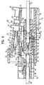
- the connector body 14 and 24 in one partially mated state shown in which the contact elements 26 are not yet inserted into the socket contact elements 18. Furthermore, the fuse element 22 is in a position between a relative to the first connector body 14, on which the securing element 22 is defined, defined in Fig. 7 and 8 starting position and a relative to the first connector body 14, on in which the securing element 32 is held defined, in FIGS. 9 and 10 shown security situation.
- the locking element 42 is located with the locking block 82 facing guide slope 54 on the guide slope 92 on, without one Resting be distracted.
- the locking element 42 with the first guide slope 54th on the second guide slope 92 of the locking block 84 by the movement forcibly guided in the insertion direction and in a direction transverse to Plugging direction, i. on the bracket 82 to and in the figures above, deflected, wherein the guided on the locking element 42 fuse element 22 and in particular its locking portion 60 on the locking element 42 are also pivoted upwards.
- the front side of the blocking portion 60 thereby becomes immediately in front of the area pivoted to the central portion of the bracket 60, so that the bracket 60 as Stop in the insertion direction of the first connector body 14 is used, the limited movement of the fuse element in this direction of insertion.
- the fuse element 22 becomes relative to the second one Connector body 24 held stationary while the fuse element 22 relative to the first connector body 14 opposite the direction of insertion in the direction of the guide and holding block 58th too moved.
- the securing element 22 can not be pushed into the backup position, as it is through the bracket 60th would be stopped. This leaves the contact portions 100 of the same as well fixed to the second connector body 24 positioned shorting element 32 with the contact elements 26 in contact, although the contact elements 26 already introduced into the socket contact elements 18 are.
- the first locking elements 68 are engaged in the recesses 68 and hold the fuse element 22 in the relative to the first connector body 14 defined starting position.
- the contact portions 100 in particular its first sections, bent up against the spring force. If no force is exerted on the securing element 22 in this state, moves the restoring force of the resilient contact portions 100 the fuse element 22 against the insertion direction in the direction of Starting position until a short circuit condition is reached.
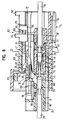
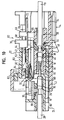
- the fuse element 22 is therefore from a mounting person to the backup position pushed, in which the lateral first locking projections 56 behind the locking shoulder 69 engage in the fuse element 14 and this as Keep complementary locking elements in the securing position.
- a movement of the locking portion 60, a deflection and thus a disengaging movement of the locking element 42 in the direction of the bracket 60th would be excluded by the strap 82 acting as another stop to limit a deflection of the locking element 42nd represents.
- the fuse element 22 and the bracket 82 thus form a Protection scheme. This is a backup of the fuse element 22 in the backup position and thus also a fuse of the connector device achieved in the assembled state.
- the separation state is obtained only by the fact that the fuse element 22 is moved from the initial position in the backup position, wherein the connector body 14 and 24 completely mated must be, and that the fuse element 22 is doing with the Actuating tongue 64 between the short-circuit element 32 and the contact elements 26 pushes.
- the fuse element 22 is doing with the Actuating tongue 64 between the short-circuit element 32 and the contact elements 26 pushes.
- the fuse element 22 in the Starting position are pushed, whereby the contact portions 100 of the Short-circuit element 26 spring back on the contact elements 26 and short this.
- the locking element 42 by means of Guiding and holding block 58 pivoted and thus deflected until the locking connection is released.
- the connector body 14 and 24 can then be pulled apart.
Landscapes
- Details Of Connecting Devices For Male And Female Coupling (AREA)
Description
- Fig. 1
- eine schematische, perspektivische Explosionsdarstellung einer Steckverbindervorrichtung nach einer bevorzugten Ausführungsform der Erfindung,
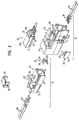
- Fig. 2
- eine schematische, perspektivische Explosionsdarstellung der Steckverbindervorrichtung in Fig. 1 aus einer anderen Perspektive,
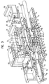
- Fig. 3
- eine perspektivische, teilweise geschnittene Ansicht der Steckverbindervorrichtung in Fig. 1 in einem teilweise zusammengesteckten Zustand, in dem sich ein Sicherungselement außerhalb einer Ausgangslage befindet,
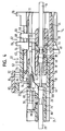
- Fig. 4
- eine schematische Schnittansicht der Steckverbindervorrichtung in Fig. 3 entlang der dort durch Schraffuren gekennzeichneten Schnittflächen von einer Seite,
- Fig. 5
- eine schematische, perspektivische, teilweise geschnittene Ansicht der Steckverbindervorrichtung in Fig. 3 während eines späteren Stadiums des Zusammensteckens von Steckverbinderkörpern der Steckvorrichtung,
- Fig. 6
- eine schematische Schnittansicht der Steckverbindervorrichtung in Fig. 5 entlang der dort durch Schraffuren gekennzeichneten Schnittflächen von der gleichen Seite wie in Fig. 4,
- Fig. 7
- eine schematische, perspektivische, teilweise geschnittene Ansicht der Steckverbindervorrichtung in Fig. 5 im zusammengesteckten, aber ungesicherten Zustand,
- Fig. 8
- eine schematische Schnittansicht der Steckverbindervorrichtung in Fig. 7 entlang der dort durch Schraffuren gekennzeichneten Schnittflächen von der gleichen Seite wie in Fig. 4,
- Fig. 9
- eine schematische, perspektivische, teilweise geschnittene Ansicht der Steckverbindervorrichtung in Fig. 7, in der ein Sicherungselement in einer Sicherungslage angeordnet ist, und
- Fig. 10
- eine schematische Schnittansicht der Steckverbindervorrichtung in Fig. 9 entlang der dort durch Schraffuren gekennzeichneten Schnittflächen von der gleichen Seite wie in Fig. 4.
- 10
- erster Steckverbinder
- 12
- zweiter Steckverbinder
- 14
- erster Steckverbinderkörper
- 16
- Kabel
- 18
- Buchsenkontaktelemente
- 20
- erster Zweitverriegelungskörper
- 22
- Sicherungselement
- 24
- zweiter Steckverbinderkörper
- 26
- Kontaktelemente
- 28
- Kabel
- 30
- zweiter Zweitverriegelungskörper
- 32
- Kurzschlusselement
- 34
- erstes Gehäuseteil
- 36
- Kontaktelementaufnahme
- 38
- Kanäle
- 40
- Steckverbinderaufnahme
- 42
- Rastelement
- 44
- Kammer
- 46
- Erstverriegelungszunge
- 48
- gabelförmiger Abschnitt
- 50
- Halteabschnitt
- 52
- Leisten
- 53
- Rastöffnung
- 54
- erste Führungsschräge
- 56
- erste Rastvorsprünge
- 58
- Führungs- und Halteblock
- 60
- Sperrabschnitt
- 62
- Führungsabschnitt
- 64
- Betätigungszunge
- 66
- Bereich
- 68
- erste Rastausnehmungen
- 69
- Rastschulter
- 70
- Betätigungsleiste
- 72
- Führungsplatten
- 74
- Betätigungsfläche
- 76
- zweites Gehäuseteil
- 78
- Kopplungsabschnitt
- 80
- zweite Kontaktelementaufnahme
- 82
- Bügel
- 84
- Rastblock
- 86
- Kanäle
- 88
- Durchbruch
- 90
- zweite Rastvorsprünge
- 92
- zweite Führungsschräge
- 94
- Führungen
- 96
- Grundplatte
- 98
- Arretierungszunge
- 100
- Kontaktabschnitte
Claims (18)
- Steckverbindervorrichtung
mit einem ersten Steckverbinderkörper (14),
einem mit dem ersten Steckverbinderkörper (14) zusammensteckbaren zweiten Steckverbinderkörper (24), in oder an dem wenigstens teilweise mindestens zwei Kontaktelemente (26) und ein Kurzschlusselement (32) angeordnet sind, die aus einem Kurzschlusszustand, in dem das Kurzschlusselement (32) die beiden Kontaktelemente (26) kurzschließt, in einen Trennzustand, in dem der Kurzschluss der Kontaktelemente (26) aufgehoben ist, versetzbar sind, und
mit einem an dem ersten Steckverbinderkörper (14) angeordneten beweglichen Sicherungselement (22), das aus einer Ausgangslage in eine Sicherungslage bewegbar ist, wenn die Steckverbinderkörper (14, 24) vollständig und nicht nur teilweise zusammengesteckt sind, wobei die Steckverbinderkörper (14, 24) in der vollständig zusammengesteckten Lage mittels eines an dem zweiten Steckverbinderkörper (24) angeordneten Sicherungselementes (82, 84) sicherbar sind,
wobei durch Bewegung des Sicherungselements (22) bei vollständig zusammengesteckten Steckverbinderkörpern (14, 24) die Kontaktelemente (26) und das Kurzschlusselement (32) aus dem Kurzschlusszustand in den Trennzustand versetzbar sind. - Steckverbindervorrichtung nach Anspruch 1,
dadurch gekennzeichnet, dass der Trennzustand nur dauerhaft erreichbar ist, wenn sich das Sicherungselement (22) in der Sicherungslage befindet. - Steckverbindervorrichtung nach Anspruch 2,
dadurch gekennzeichnet, dass die Kontaktelemente (26) und das Kurzschlusselement (32) bei zusammengesteckten Steckverbinderkörpern (14, 24) nur dann in dem Trennzustand sind, wenn das Sicherungselement (22) in der Sicherungslage ist. - Steckverbindervorrichtung nach Anspruch 1 oder 2,
dadurch gekennzeichnet, dass ein federndes Element (100) vorgesehen ist, das bei einer Bewegung des Sicherungselements (22) in die Sicherungslage spannbar ist, und mittels dessen das Sicherungselement (22) aus einer Lage zwischen der Sicherungslage und der Ausgangslage, in der der Kurzschlusszustand aufgehoben ist, wenigstens soweit in Richtung der Ausgangslage bewegbar ist, dass der Kurzschlusszustand erreicht wird. - Steckverbindervorrichtung nach einem der vorhergehenden Ansprüche,
dadurch gekennzeichnet, dass das Sicherungselement (22) und wenigstens einer der Steckverbinderkörper (14) komplementäre Rastelemente (56, 69) aufweisen, mittels derer das Sicherungselement (22) in der Sicherungslage verrastbar ist. - Steckverbindervorrichtung nach einem der vorhergehenden Ansprüche, dadurch gekennzeichnet, dass das Kurzschlusselement (32) wenigstens ein federndes Element, insbesondere einen federnden Kontaktabschnitt (100), aufweist, der in dem Kurzschlusszustand auf einem der Kontaktelemente (26) aufliegt und der durch Bewegung des Sicherungselements (22) in die Sicherungslage von dem Kontaktelement (26) wegbewegbar ist.
- Steckverbindervorrichtung nach einem der vorhergehenden Ansprüche,
dadurch gekennzeichnet, dass eines der Kontaktelemente einen federnden Kontaktabschnitt aufweist, der in dem Kurzschlusszustand auf dem Kurzschlusselement aufliegt und der durch Bewegung des Sicherungselements in die Sicherungslage von dem Kurzschlusselement wegbewegbar ist - Steckverbindervorrichtung nach einem der Ansprüche 6 oder 7,
dadurch gekennzeichnet, dass das Sicherungselement (22) eine Zunge aufweist, die durch Bewegung des Sicherungselements (22) in die Sicherungslage zwischen den Kontaktabschnitt (100) und das Kontaktelement (26) bzw. das Kurzschlusselement (32) bewegbar ist. - Steckverbindervorrichtung nach einem der vorhergehenden Ansprüche,
dadurch gekennzeichnet, dass das Sicherungselement (22) an dem ersten Steckverbinderkörper (14) gehalten ist. - Steckverbindervorrichtung nach einem der vorhergehenden Ansprüche,
dadurch gekennzeichnet, dass das Sicherungselement (22) im Wesentlichen entlang einer Steckrichtung, in der die Steckverbinderkörper (14, 24) zusammensteckbar sind, verschiebbar ist. - Steckverbindervorrichtung nach einem der vorhergehenden Ansprüche,
dadurch gekennzeichnet, dass die Steckverbinderkörper (14, 24) zwei zueinander komplementäre Schnapp- oder Rastelemente (42, 84) aufweisen, mittels derer die Steckverbinderkörper (14, 24) in dem vollständig zusammengesteckten Zustand miteinander verbindbar sind. - Steckverbindervorrichtung nach einem der vorhergehenden Ansprüche,
dadurch gekennzeichnet, dass eines der komplementären Schnapp- oder Rastelemente (42) zur Herstellung der Schnapp- oder Rastverbindung auslenkbar ist. - Steckverbindervorrichtung nach Anspruch 12,
dadurch gekennzeichnet, dass eines der Schnapp- oder Rastelemente (42, 84) eine Führungsschräge (54, 92) aufweist, mittels derer die Schnapp- oder Rastelemente (42, 84) relativ zueinander führbar sind, so dass durch Zusammenstecken der Steckverbinderkörper (14, 24) das auslenkbare Schnapp- oder Rastelement (42) mittels der Führungsschräge (54, 92) auslenkbar ist. - Steckverbindervorrichtung nach Anspruch 12 oder 13,
dadurch gekennzeichnet, dass bei einer Auslenkung des auslenkbaren Schnapp- oder Rastelements (42) zur Herstellung der Schnapp- oder Rastverbindung das auslenkbare Schnapp- oder Rastelement (42) in einer Bewegungsbahn des Sicherungselements (22) zwischen der Ausgangslage und der Sicherungslage angeordnet ist, und/oder dass das Sicherungselement (22) in der Sicherungslage eine Auslenkung des auslenkbaren Schnapp- oder Rastelements (42) begrenzt. - Steckverbindervorrichtung nach einem der vorhergehenden Ansprüche,
dadurch gekennzeichnet, dass das Sicherungselement (22) durch Zusammenstecken der Steckverbinderkörper (14, 24) in die Ausgangslage bewegbar ist. - Steckverbindervorrichtung nach Anspruch 15 und einem der Ansprüche 12 bis 14,
dadurch gekennzeichnet, dass das Sicherungselement (22) durch die Auslenkung des auslenkbaren Schnapp- oder Rastelements (42) in Richtung der Ausgangslage bewegbar ist. - Steckverbindervorrichtung nach Anspruch 15 oder 16 und einem der Ansprüche 12 bis 14,
dadurch gekennzeichnet, dass das Sicherungselement (22) an dem auslenkbaren Schnapp- oder Rastelement (42), das an einem der Steckverbinderkörper (14) gehalten ist, geführt ist, und
dass an dem anderen Steckverbinderkörper (24) ein Vorsprung (82) vorgesehen ist, der eine Bewegung des Sicherungselements (22) relativ zu dem Steckverbinderkörper (14), an dem es geführt ist, beim Zusammenstecken der Steckverbinderkörper (14, 24) und bei Auslenkung des auslenkbaren Schnapp- oder Rastelements (42) begrenzt. - Steckverbindervorrichtung nach Anspruch 17,
dadurch gekennzeichnet, dass ein weiterer Anschlag (42) in Richtung der Auslenkung vorgesehen ist, unter den das Sicherungselement (22) bei Bewegung in die Sicherungslage bewegbar ist und mittels dessen eine Auslenkung des auslenkbaren Schnapp- oder Rastelements (42) und des daran geführten Sicherungselements (22) in der Sicherungslage begrenzbar ist.
Priority Applications (2)
| Application Number | Priority Date | Filing Date | Title |
|---|---|---|---|
| DE50301917T DE50301917D1 (de) | 2003-02-14 | 2003-02-14 | Steckverbinder mit einem Kurzschlusskontakt |
| EP03003432A EP1455423B1 (de) | 2003-02-14 | 2003-02-14 | Steckverbinder mit einem Kurzschlusskontakt |
Applications Claiming Priority (1)
| Application Number | Priority Date | Filing Date | Title |
|---|---|---|---|
| EP03003432A EP1455423B1 (de) | 2003-02-14 | 2003-02-14 | Steckverbinder mit einem Kurzschlusskontakt |
Publications (2)
| Publication Number | Publication Date |
|---|---|
| EP1455423A1 EP1455423A1 (de) | 2004-09-08 |
| EP1455423B1 true EP1455423B1 (de) | 2005-12-14 |
Family
ID=32798740
Family Applications (1)
| Application Number | Title | Priority Date | Filing Date |
|---|---|---|---|
| EP03003432A Expired - Lifetime EP1455423B1 (de) | 2003-02-14 | 2003-02-14 | Steckverbinder mit einem Kurzschlusskontakt |
Country Status (2)
| Country | Link |
|---|---|
| EP (1) | EP1455423B1 (de) |
| DE (1) | DE50301917D1 (de) |
Families Citing this family (6)
| Publication number | Priority date | Publication date | Assignee | Title |
|---|---|---|---|---|
| DE102006031838B4 (de) * | 2006-07-07 | 2011-03-31 | Tyco Electronics Amp Gmbh | Aktivierbare elektrische Steckverbindung für einen Airbaganschluss |
| DE102007005349A1 (de) * | 2007-02-02 | 2008-08-07 | Tyco Electronics Amp Gmbh | Abgedichteter Airbagsteckverbinder |
| JP4876985B2 (ja) * | 2007-03-09 | 2012-02-15 | 住友電装株式会社 | コネクタ |
| US8894435B2 (en) * | 2013-03-04 | 2014-11-25 | Tyco Electronics Corporation | Sense pin for an electrical connector |
| EP3627977B1 (de) * | 2017-05-16 | 2022-11-02 | Fuji Corporation | Plasmagenerator |
| KR102511696B1 (ko) * | 2021-04-21 | 2023-03-21 | (주)우주일렉트로닉스 | 접촉 신뢰성이 향상된 접촉스위치를 갖는 커넥터 장치 |
Family Cites Families (3)
| Publication number | Priority date | Publication date | Assignee | Title |
|---|---|---|---|---|
| BR7802885Y1 (pt) * | 1997-09-09 | 2010-08-10 | disposição introduzida em conector elétrico com trava. | |
| FR2784240B1 (fr) * | 1998-09-16 | 2000-11-17 | Framatome Connectors Int | Dispositif d'actionnement d'au moins un shunt dans un connecteur notamment a etrier mobile |
| US6186805B1 (en) * | 1999-08-31 | 2001-02-13 | Molex Incorporated | Short circuit electrical connector |
-
2003
- 2003-02-14 DE DE50301917T patent/DE50301917D1/de not_active Expired - Fee Related
- 2003-02-14 EP EP03003432A patent/EP1455423B1/de not_active Expired - Lifetime
Also Published As
| Publication number | Publication date |
|---|---|
| DE50301917D1 (de) | 2006-01-19 |
| EP1455423A1 (de) | 2004-09-08 |
Similar Documents
| Publication | Publication Date | Title |
|---|---|---|
| DE102008028933B4 (de) | Stromkreisunterbrechungsvorrichtung | |
| DE69521580T2 (de) | Elektrischer Verbinder mit Kontaktlagesicherungsvorrichtung welche das vollständige Einsetzen der Kontakte erleichtert | |
| DE69517492T2 (de) | Elektrischer Verbinder mit einer rückseitigen Lagesicherungsvorrichtung der Kontakte | |
| EP1972037B1 (de) | Elektrische steckerbuchse | |
| DE10346914B4 (de) | Verbinder und Verbinderanordnung | |
| DE69022612T2 (de) | Elektrischer Steckverbinder. | |
| DE4311767A1 (de) | Elektrische Verbinderanordnung | |
| DE60205152T2 (de) | Ankopplungsdetektor für Verbinder | |
| DE60303341T2 (de) | Elektrische Steckverbinderanordnung mit Kurzschlusselement | |
| DE102019220446A1 (de) | Elektrischer Verbinder mit Verbinderpositionssicherung | |
| DE8336870U1 (de) | Elektrischer Verbinder | |
| DE10346916B4 (de) | Verbinder und Verbinderanordnung | |
| DE69803463T2 (de) | Zündpillen-steckverbinder | |
| EP1730819B1 (de) | Elektrisches nullkraftsteckverbindungsteil | |
| DE102014110445B4 (de) | Elektrische Verbinderanordnung | |
| EP4000139A1 (de) | Kontaktelement | |
| DE69514503T2 (de) | Lagersicherungsvorrichtung der Endkontakte eines elektrischen Verbinders | |
| DE69404891T2 (de) | Verbinder mit Kurzschlusskontakt | |
| DE19702373B4 (de) | Elektrischer Steckverbinder mit einer Kurzschlußfeder und Kurzschlußfeder | |
| EP1455423B1 (de) | Steckverbinder mit einem Kurzschlusskontakt | |
| EP1760844B1 (de) | Stecker oder Kuppler einer Steckverbindung für die Anwendung im Fahrzeugbereich mit einer Kurzschlussbrücke | |
| EP3504760B1 (de) | Mehrfachkontaktstecker mit integriertem kurzschlussbrückenelement | |
| DE69406376T2 (de) | Elektrische Verbindungsvorrichtung, insbesondere für Hochstromdurchgang | |
| DE10326834B4 (de) | Steckverbinder | |
| DE102006031838B4 (de) | Aktivierbare elektrische Steckverbindung für einen Airbaganschluss |
Legal Events
| Date | Code | Title | Description |
|---|---|---|---|
| PUAI | Public reference made under article 153(3) epc to a published international application that has entered the european phase |
Free format text: ORIGINAL CODE: 0009012 |
|
| 17P | Request for examination filed |
Effective date: 20040326 |
|
| AK | Designated contracting states |
Kind code of ref document: A1 Designated state(s): AT BE BG CH CY CZ DE DK EE ES FI FR GB GR HU IE IT LI LU MC NL PT SE SI SK TR |
|
| AX | Request for extension of the european patent |
Extension state: AL LT LV MK RO |
|
| GRAP | Despatch of communication of intention to grant a patent |
Free format text: ORIGINAL CODE: EPIDOSNIGR1 |
|
| GRAS | Grant fee paid |
Free format text: ORIGINAL CODE: EPIDOSNIGR3 |
|
| AKX | Designation fees paid |
Designated state(s): DE FR IT |
|
| GRAA | (expected) grant |
Free format text: ORIGINAL CODE: 0009210 |
|
| AK | Designated contracting states |
Kind code of ref document: B1 Designated state(s): DE FR IT |
|
| REF | Corresponds to: |
Ref document number: 50301917 Country of ref document: DE Date of ref document: 20060119 Kind code of ref document: P |
|
| ET | Fr: translation filed | ||
| PLBE | No opposition filed within time limit |
Free format text: ORIGINAL CODE: 0009261 |
|
| STAA | Information on the status of an ep patent application or granted ep patent |
Free format text: STATUS: NO OPPOSITION FILED WITHIN TIME LIMIT |
|
| 26N | No opposition filed |
Effective date: 20060915 |
|
| PGFP | Annual fee paid to national office [announced via postgrant information from national office to epo] |
Ref country code: DE Payment date: 20080207 Year of fee payment: 6 Ref country code: IT Payment date: 20080227 Year of fee payment: 6 |
|
| PGFP | Annual fee paid to national office [announced via postgrant information from national office to epo] |
Ref country code: FR Payment date: 20080208 Year of fee payment: 6 |
|
| REG | Reference to a national code |
Ref country code: FR Ref legal event code: ST Effective date: 20091030 |
|
| PG25 | Lapsed in a contracting state [announced via postgrant information from national office to epo] |
Ref country code: DE Free format text: LAPSE BECAUSE OF NON-PAYMENT OF DUE FEES Effective date: 20090901 |
|
| PG25 | Lapsed in a contracting state [announced via postgrant information from national office to epo] |
Ref country code: FR Free format text: LAPSE BECAUSE OF NON-PAYMENT OF DUE FEES Effective date: 20090302 |
|
| PG25 | Lapsed in a contracting state [announced via postgrant information from national office to epo] |
Ref country code: IT Free format text: LAPSE BECAUSE OF NON-PAYMENT OF DUE FEES Effective date: 20090214 |