EP1455497A2 - Mobiles Kommunikationsendgerät welches sowohl ein kontinuierliches als auch ein intermittierendes Pilotsignal zur Kanalschätzung verwendet - Google Patents
Mobiles Kommunikationsendgerät welches sowohl ein kontinuierliches als auch ein intermittierendes Pilotsignal zur Kanalschätzung verwendet Download PDFInfo
- Publication number
- EP1455497A2 EP1455497A2 EP04012439A EP04012439A EP1455497A2 EP 1455497 A2 EP1455497 A2 EP 1455497A2 EP 04012439 A EP04012439 A EP 04012439A EP 04012439 A EP04012439 A EP 04012439A EP 1455497 A2 EP1455497 A2 EP 1455497A2
- Authority
- EP
- European Patent Office
- Prior art keywords
- mobile communication
- communication terminal
- pilot signal
- known signal
- reception
- Prior art date
- Legal status (The legal status is an assumption and is not a legal conclusion. Google has not performed a legal analysis and makes no representation as to the accuracy of the status listed.)
- Ceased
Links
Images



Classifications
-
- H—ELECTRICITY
- H04—ELECTRIC COMMUNICATION TECHNIQUE
- H04L—TRANSMISSION OF DIGITAL INFORMATION, e.g. TELEGRAPHIC COMMUNICATION
- H04L25/00—Baseband systems
- H04L25/02—Details ; arrangements for supplying electrical power along data transmission lines
- H04L25/0202—Channel estimation
- H04L25/0224—Channel estimation using sounding signals
- H04L25/0228—Channel estimation using sounding signals with direct estimation from sounding signals
- H04L25/023—Channel estimation using sounding signals with direct estimation from sounding signals with extension to other symbols
- H04L25/0232—Channel estimation using sounding signals with direct estimation from sounding signals with extension to other symbols by interpolation between sounding signals
-
- H—ELECTRICITY
- H04—ELECTRIC COMMUNICATION TECHNIQUE
- H04L—TRANSMISSION OF DIGITAL INFORMATION, e.g. TELEGRAPHIC COMMUNICATION
- H04L27/00—Modulated-carrier systems
- H04L27/18—Phase-modulated carrier systems, i.e. using phase-shift keying
- H04L27/22—Demodulator circuits; Receiver circuits
- H04L27/233—Demodulator circuits; Receiver circuits using non-coherent demodulation
- H04L27/2332—Demodulator circuits; Receiver circuits using non-coherent demodulation using a non-coherent carrier
Definitions
- This invention relates to a mobile communication terminal, and for example to a mobile communication terminal which adopts the CDMA (Code Division Multiple Access) communication system and uses two different systems of pilot signals to achieve improvement of the channel estimation precision.
- CDMA Code Division Multiple Access
- the pilot signal transmitted from the radio base station is received by a mobile communication terminal.
- the mobile communication terminal estimates (channel estimation) the phase rotation amount by which the received signal is to be corrected with the pilot signal and performs phase correction of the received signal to realize synchronous detection.
- the pilot signal used here usually an individual communication channel allocated to each mobile communication terminal and an interpolation pilot signal spread with the same code are available.
- a radio base station transmits, in addition to such an interpolation pilot signal as described above, an extrapolation pilot signal in which a fixed data pattern (for example, all "0s") is spread with a code different from that of a communication channel (but having the same frequency) using a channel common to different mobile communication terminals whereas a mobile communication terminal of the reception side uses the extrapolation pilot signal to estimate such a phase rotation amount as described above.
- a fixed data pattern for example, all "0s”
- TPC control Transmission Power Control
- a forward-link communication channel from a radio base station to a mobile communication terminal
- the transmission power increases.
- Embodiments of the present invention can provide a mobile communication terminal which uses both an extrapolation pilot signal and an interpolation pilot signal taking characteristics of them into consideration to achieve improvement of the channel estimation precision and also of the synchronous detection capacity.
- a mobile communication terminal for CDMA communication wherein a pilot signal is used for phase correction of a reception signal, comprising a first pilot signal despreading section for despreading a first pilot signal spread with a spread code different from a spread code of a communication channel including the data signal, a second pilot signal despreading section for despreading a second pilot signal inserted in the data signal and spread with a spread code same as the spread code for the data signal, a first complex calculation section for performing complex calculation processing for the signal for which the despreading processing has been performed by the first pilot signal despreading section and outputting a result of the complex calculation processing as a first calculation processing result, a second complex calculation section for performing complex calculation processing for the signal for which the despreading processing has been performed by the second pilot signal despreading section and outputting a result of the complex calculation processing as a second calculation processing result, and a correction amount output section for outputting a phase correction amount for the phase correction using the first
- the correction amount output section includes a first reception quality measurement section for measuring a first reception quality index value by the first pilot signal using the first calculation processing result, a second reception quality measurement section for measuring a second reception quality index value by the second pilot signal using the second calculation processing result, a first phase correction amount calculation section for calculating a phase correction amount for the reception signal using the first calculation processing result and outputting the phase correction amount as a first correction amount, a second phase correction amount calculation section for calculating a phase correction amount for the reception signal using the second calculation processing result and outputting the phase correction amount as a second correction amount, a distribution ratio setting section for setting distribution ratio parameters for the first correction amount and the second correction amount based on the first reception quality index value and the second reception quality index value, and an output section for calculating values with which the first correction amount and the second correction amount are distributed based on the distribution ratio parameters from the distribution ratio setting section and outputting the values as the phase correction amount.
- the distribution ratio setting section may set the distribution ratio parameters such that, as the first reception quality index value deteriorates relative to the second reception quality index value, the distribution ratio of the second correction amount increases relative to the distribution ratio of the first correction amount.
- the distribution ratio setting section may set the distribution ratio parameters such that, where the first reception quality index value is higher than the second reception quality index value, the first correction amount from the first phase correction amount calculation section is outputted as the phase correction amount, but where the first reception quality index value is lower than the second reception quality index value, the second correction amount from the second phase correction amount calculation section is outputted as the phase correction amount.
- the distribution ratio setting section may set, for the second reception quality index value which is an object of discrimination in magnitude from the first reception quality index value, a comparison margin value corresponding to the kind of the reception quality index value, and set the distribution ratio parameters corresponding to the first reception quality index value and a value obtained by adding the comparison margin value to the second reception quality index value.
- a mobile communication terminal for CDMA communication wherein a phase correction amount of a reception signal to be corrected is estimated using a received pilot signal, comprising an estimation result output section for estimating the phase correction amount based on plural pilot signals spread with different spread codes and transmitted to the mobile communication terminal.
- the pilot signals spread with the different spread codes include a first pilot signal transmitted intermittently with individual communication channels outside a data signal transmission period and a second pilot signal transmitted with a communication channel also within the data signal transmission period, and the estimation result output section estimates the phase correction amount such that, as the reception quality of the second pilot signal deteriorates, the degree of influence of the first pilot signal is raised in comparison with the degree of influence of the second pilot signal.
- a mobile communication terminal for a mobile communication system wherein channel estimation is performed using a known signal, comprising a channel estimation section for performing channel estimation using a first known signal to be used commonly by a plurality of mobile communication terminals and a second known signal to be used by a particular mobile communication terminal.
- the channel estimation section weights the first known signal and the second known signal in response to a reception quality of the first known signal and a reception quality of the second known signal to perform the channel estimation.
- the channel estimation section may weight the first known signal or the secondknown signal in response to a reception quality of the first known signal or a reception quality of the second known signal to perform the channel estimation.
- the correction amount output section uses both of a first calculation processing result and a second calculation processing result and outputs a phase rotation amount for phase correction for a reception signal as an estimation result. Consequently, since both of an extrapolation pilot signal and an interpolation pilot signal are used, not only the precision in estimation can be improved and the stability can be assured, but also a good reception sensitivity after phase correction can be assured. As a result, the transmission power control can be optimized, and the transmission level of the radio base station can be lowered thereby to increase the system capacity.
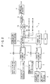
- FIG. 1 is a block diagram showing a reception system of a mobile communication terminal according to the embodiment of the present invention.
- FIG. 2 is a block diagram showing a transmission system of a base station. The transmission system has a function of transmitting an interpolation pilot signal (second pilot signal) and an extrapolation pilot signal (first pilot signal).
- second pilot signal an interpolation pilot signal
- first pilot signal an extrapolation pilot signal
- the transmission system of the base station which is a premise of operation of the reception system of the mobile communication terminal is described taking notice of transmission methods of an extrapolation pilot signal and an interpolation pilot signal and a manner of transmission power control.
- a transmission system 18 of a radio base station (whichmay be hereinafter referred to merely as a base station) shown includes, as spread codes, a channelization code 1 for an extrapolation pilot signal, a scrambling code 2 characteristic to the base station, and channelization codes 3 (in FIG. 2, only that for a communication channel #1 is shown) for individual communication channels #1 to #n.
- the channelization code 1 for an extrapolation pilot signal described above and channelization codes for the communication channels are different from each other. That is, the extrapolation pilot signal is transmitted as a channel separate from the channels #1 to #n.
- reference numeral 5 denotes an adder which adds the channelization code 1 and the scrambling code 2.
- Reference numeral 6 denotes a spread I/Q value formation section which performs a spreading process for fixed data 4 for an extrapolation pilot signal using the spread code added by the adder 5 and outputs resulting data as I/Q values.
- the fixed data 4 for an extrapolation pilot signal data of a known pattern (for example, data such as all "0s") can be used as the fixed data 4 for an extrapolation pilot signal.
- Reference numeral 9 denotes a selection section which selectively outputs either one of fixed data 7 for an interpolation pilot signal and data of the communication channel #1 (individual CH data #1) 8.
- the fixed data 7 for an interpolation pilot signal can be inserted into and outputted together with the data 8 of the communication channel #1 (individual CH data #1) by the selection section 9.
- Reference numeral 10 denotes an adder which adds the channelization code 3 for the communication channel #1 and the scrambling code 2
- reference numeral 11 denotes a spread I/Q value formation section which performs a spreading process for the data of the communication channel #1 and outputs resulting data as I/Q values.
- the spread I/Q value formation section 11 performs the spreading process for the data 8, in which the fixed data 7 for an interpolation pilot signal is inserted, using the spread code added by the adder 10 and outputs resulting data as I/Q values.
- Reference numeral 12 denotes a TPC section which outputs an instruction for controlling the transmission power to a mobile communication terminal.
- Reference numeral 13 denotes a forward link power control section which controls the transmission power (forward link power) of the spread data of the channel #1 from the spread I/Q value formation section 11 based on the instruction from the TPC section 12. It is to be noted that, while the function sections for the data of the communication channel #1 are described, other non-illustrated function sections corresponding to the selection section 9, adder 10, spread I/Q value formation section 11, TPC section 12 and forward link power control section 13 may be provided for the other communication channels #2 to #N.
- reference characters 14I and 14Q each denotes an adder.
- the adder 14I adds the data (I value) spread by the spread I/Q value formation section 6 and data (I values) of the communication channels #1 to #N to which power control is performed.
- the adder 14Q adds the data (Q value) spread by the spread I/Q value formation section 6 and data (Qvalues) of the communication channels #1 to #N to which the power control is performed.
- Reference character 15A denotes a cosine multiplication section which multiplies data from the adder 14I by a cosine function (cos) .
- Reference character 15B denotes a sine multiplication section which multiplies data from the adder 14Q by a sine function (-sin).
- Reference numeral 16 denotes an adder which adds arithmetic operation results from the cosine multiplication section 15A and the sine multiplication section 15B.
- the cosine multiplication section 15A, sine multiplication section 15B and adder 16 can convert data from I /Q values back into original vector information.
- reference numeral 17 denotes a transmission amplification RF section.
- the transmission amplification RF section 17 performs amplification and RF (Radio Frequency) signal processing for a transmission signal in the form of a vector and performs radio transmission of a resulting signal to a mobile communication terminal.
- RF Radio Frequency
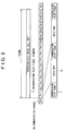
- the data of the communication channels and the spread data of the extrapolation pilot signal are transmitted, for example, at such a timing as illustrated in FIG. 3.
- an extrapolation pilot signal 4' and effective symbols of the communication channels are transmitted at the same timing (same propagation path) .
- the extrapolation pilot signal in a unit of 1 frame and the data (TS1 to TS15) of the communication channel in a unit of 15 slots can be transmitted in synchronism with each other.
- the interpolation pilot signal is periodically inserted into data of the communication channels 8A and, more particularly, is time division multiplexed in the data slots of the communication channels 8A.
- a data slot formed from a pair of an interpolation pilot signal 7' and a data part 8' is formed by selectively outputting data for an interpolation pilot signal in a unit of data of a predetermined length.
- the reception system 30 of the mobile communication terminal is configured, for example, in such a manner as shown in FIG. 1.
- reference numeral 19 denotes a radio reception section (Rx) which receives a transmission signal from the transmission system 18 of the base station by radio and converts it into an electric signal.
- Reference numeral 20 denotes a path detection section which detects a path of a reception signal.
- the path detection section 20 includes a matched filter (MF) 20a and a searcher 20c.
- the matched filter 20a calculates a correlation between bit data of the reception signal from the radio reception section 19 and a spread code 20b for an extrapolation pilot signal.
- the searcher 20c extracts reception timings (t1 to t3) of reception signals received through a plurality of paths (in FIG. 1, three paths) based on the correlation value calculated by the matched filter 20a.
- Reference numeral 21 denotes a spread code generator which generates a spread code for an extrapolation pilot signal.
- Reference characters 22-1 to 22-3 each denotes a despreading section which performs despreading for the reception signal from the radio reception section 19 using a spread code for an extrapolation pilot signal generated by the spread code generator 21 based on the reception timings of the reception signal in the path extracted by the searcher 20c.
- the despreading section 22-1 performs despreading for the reception signal from the radio reception section 19 using the spread code generated by the spread code generator 21 based on the reception timing t1 from the path detection section 20.
- the despreading section 22-2 performs the despreading for the reception signal received at the reception timing t2 with the spread code just described.
- the despreading section 22-3 performs despreading for the reception signal received at the reception timing t3 using the spread code just described.
- the despreading sections 22-1 to 22-3 have a function as a first pilot signal despreading section which performs despreading for the first pilot signal spread with a spread code separate from a spread code of a communication channel including a data signal.
- Reference numeral 23 denotes a channel estimation apparatus.
- the channel estimation apparatus 23 estimates a phase correction amount (phase rotation amount) for phase correction sections 27-1 to 27-3 which are hereinafter described. More particularly, the channel estimation apparatus 23 uses an extrapolation pilot signal and an interpolation pilot signal both as pilot signals used for channel estimation described below.
- Reference numeral 24 denotes an offset setting section which performs setting of an offset timing ⁇ for each communication channel.
- Reference numeral 25 denotes a spread code generator which generates a spread code for a communication channel (a spread code for an interpolation pilot signal and data).
- Reference characters 26-1 to 26-3 each denotes a despreading section which performs despreading for a reception signal from the radio reception section 19 with a spread code from the spread code generator 25 based on reception timings to which the offset timing ⁇ has been added by the offset setting section 24.
- the despreading section 26-1 despreads a reception signal with a spread code of the communication channel based on a reception timing t1+ ⁇ .
- the despreading section 26-2 despreads a reception signal with a spread code of the communication channel based on a reception timing t2+ ⁇ .
- the despreading section 26-3 despreads a reception signal with a spread code of the communication channel based on a reception timing t3+ ⁇ .
- despreading sections 26-1 to 26-3 described above have a function as a second pilot signal despreading section which despreads a second pilot signal inserted in a data signal and spread with a spread code which is the same as used for the data signal.
- the phase correction sections 27-1 to 27-3 perform phase correction for reception signals despread by the corresponding despreading sections 26-1 to 26-3 using phase rotation amounts of the individual reception signals in correspondence paths estimated by the channel estimation apparatus 23.
- Reference characters 28-1 to 28-3 each denotes a delay adjustment section.
- the delay adjustment sections 28-1 to 28-3 perform delay adjustment for signals from the phase correction sections 27-1 to 27-3 so that data of the reception timings based on route differences among the paths may be data at the same timing.
- a Rake combination section 29 performs Rake combination for three reception signals so that the reception timings are adjusted to the same timing by the delay adjustment sections 28-1 to 28-3.
- the propagation paths (phase rotation amounts) of the paths are estimated by the channel estimation apparatus 23, and correction of the phase rotation amount is performed for all effective paths by the phase correction sections 27-1 to 27-3. Consequently, the S/N ratio of the reception signal obtained by the Rake combination by the Rake combination section 29 is improved and the reception characteristic is improved.
- a desired signal playback process (for example, playback or the like as a voice signal) is performed for the signal obtained by the Rake combination after a decoding process, an error correction process and so forth are performed.
- the channel estimation apparatus 23 described above particularly includes complex calculation sections 23a and 23b, channel estimation sections 23c and 23d, RSCP/SIR measurement sections 23e and 23f, a controller 23g, and an estimation value selection logic section 23h.
- the complex calculation section (first complex calculation section) 23a demodulates an extrapolation pilot signal by performing a complex calculation process for the despread extrapolation pilot signals from the despreading sections 22-1 to 22-3.
- the demodulated signals are outputted as a first complex calculation process result.
- the channel estimation section (first phase correction amount estimation section) 23c uses the first complex calculation process result from the complex calculation section 23a to calculate a phase rotation amount with respect to a known phase (a phase correction amount for the reception signal).
- a result of the calculation is outputted as a first correction amount to the estimation value selection logic section 23h in the following stage.
- the complex calculation section (second complex calculation section) 23b demodulates an interpolation pilot signal by performing a complex calculation process for the despread interpolation pilot signals from the despreading sections 26-1 to 26-3.
- the demodulated interpolation pilot signal is outputted as a second complex calculation process result.
- the channel estimation section (second phase correction amount estimation section) 23d uses the second complex calculation process result from the complex calculation section 23b to calculate a phase rotation amount with respect to a known phase (a phase correction amount for the reception signal).
- a result of the calculation is outputted as a second correction amount to the estimation value selection logic section 23h in the following stage.
- the two complex calculation sections 23a and 23b described above almost usually perform parallel operation for SIR measurement and hand-over control during communication.
- the RSCP/SIR measurement sections 23e and 23f measure an RSCP (Received Signal Code Power; reception level (which may be referred to also as code power) ) and an SIR (Signal to Interference and noise power Ratio) for both pilot signals.
- RSCP Receiveived Signal Code Power
- reception level which may be referred to also as code power
- SIR Signal to Interference and noise power Ratio
- the RSCP/SIR measurement section 23e has a function as a first reception quality measurement section which measures first reception quality index values (a reception level and an SIR) of an extrapolation pilot signal as a first pilot signal.
- the RSCP/SIR measurement section 23f has a function as a second reception quality measurement section which measures second reception quality index values (a reception level and an SIR) of an interpolation pilot signal as a second pilot signal.
- the RSCP/SIR measurement section 23f averages reception levels and SIRs as reception quality index value data measured in a predetermined cycle and uses the average values as measurement values of a reception quality index value by an interpolation pilot signal. Consequently, the precision as a reception quality index value by an interpolation pilot signal is secured.
- the controller 23g receives reception level values and SIR values transmitted from the RSCP/SIR measurement sections 23e and 23f, and estimates an external reception environment from the values just described and sets and controls distribution ratio parameters for the estimation value selection logic section 23h, particularly, distribution ratio parameters for a phase rotation amount (refer to Vcp of an expression (1) given below) from the channel estimation section 23c and another phase rotation amount (refer to Vdp of the same expression) from the channel estimation section 23d.
- the controller 23g has a function as a distribution ratio setting section for setting a distribution ratio parameter for the first correction amount and the second correction amount described above based on a first reception quality index value and a second reception quality index value.
- the controller 23g includes a reference table 23i which stores distribution ratio parameters (refer to ⁇ and ⁇ in the expression (1) given below) and interference correction values (refer to A and B of the expression (1) given below) for canceling an influence of a known fixed interference wave in accordance with the reception level values and the SIR values measured from the interpolation pilot signal and the extrapolation pilot signal described above.
- controller 23g can control to output a distribution ratio parameter and a phase correction value described above by referring to the reference table 23i based on the reception level values and the SIR values from the RSCP/SIR measurement sections 23e and 23f. Consequently, an optimum control parameter which is estimated to vary depending upon the configuration of hardware and an operation condition can be extracted quickly by memory accessing.
- the reference table 23i stores optimum distribution ratio parameters ( ⁇ and ⁇ appearing in the expression (1) given below), which are set in accordance with a combination of a range of the SIR value and a range of a reception level of each pilot signal, and interference correction amounts (A and B appearing in the same expression). Further, if the situation varies as a result of variation of a reception method or the like (for example, fluctuation of the intersymbol interference amount) , then the table is changed to cope with the variation of the situation.
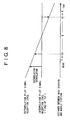
- the controller 23g sets a distribution ratio index so that a phase rotation amount may be estimated using only a demodulated extrapolation pilot signal (refer to a range P of the distance between a base station and a mobile station in FIG. 8).
- the controller 23g sets the distribution ratio parameter so that the phase rotation amount may be estimated using only the demodulated interpolation pilot signal (refer to a range R of the distance between the base station and the mobile station in FIG. 8).
- the estimation value selection logic section 23h estimates a phase rotation amount using both of the demodulated extrapolation pilot signal and the demodulated interpolation pilot signal. More particularly, the distribution ratio parameter by the controller 23g is set such that the distribution ratio of the channel estimation value (second correction amount) from the channel estimation section 23d increases relative to the distribution ratio of the channel estimation value (first correction amount) from the channel estimation section 23c as the reception quality index value of the demodulated extrapolation pilot signal decreases relation to the reception quality index value of the interpolation pilot signal.
- a comparison margin value in accordance with the type of the reception quality index value to the reception quality index value according to the interpolation pilot signal which is a comparison object for size discrimination with the reception quality index value according to the extrapolation pilot signal is set, and the controller 23g can set a distribution ratio parameter in accordance with the magnitudes of the values.
- the estimation value selection logic section 23h receives the channel estimation values from the channel estimation section 23c and the channel estimation section 23d described above and also receives the distribution ratio parameter or the interference correction value from the controller 23g, and calculates a phase rotation amount of the pertaining path by calculation based on an expression for calculation which uses the values.
- the estimation value selection logic section 23h calculates a final phase rotation amount Vch in accordance with an expression (1) given below.
- a phase rotation amount calculated for each of the paths in accordance with the expression (1) by the estimation value selection logic section 23h is outputted to the phase correction sections 27-1 to 27-3 to perform phase correction:
- Vch ⁇ ⁇ ( Vcp - A) + ⁇ ⁇ (Vdp - B)
- Vcp represents the phase rotation amount (vector amount, output of the channel estimation section 23c of FIG. 1) based on the extrapolation pilot signal
- Vdp represents the phase rotation amount (vector amount, output of the channel estimation section 23d of FIG. 1) based on the interpolation pilot signal
- ⁇ and ⁇ represent distribution ratio parameters which determine distribution of extrapolation/interpolation
- a and B represent correction values (vector amounts) for known fixed interference.
- the estimation value selection logic section 23h calculates a value (calculation result of the expression (1)) distributed with the distribution ratio parameters based on the calculation process results (Vcp-A) and (Vdp-B) corrected with the interference correction values A and B, respectively, and outputs it as a phase rotation amount (estimation result) for each path.
- the estimation value selection logic section 23h has a function as an output section which calculates values with which the calculation result from the channel estimation section 23c as a first correction amount and the calculation result from the channel estimation result 23d as a second correction amount are distributed based on the distribution ratio parameter from the controller 23g, and outputs the resulting values as phase correction amounts (estimation results).
- the channel estimation sections 23c and 23d, RSCP/SIR measurement sections 23e and 23f, controller 23g and estimation value selection logic section 23h have a function as a correction amount output section which outputs a phase correction amount for a reception signal using a calculation result from the complex calculation process section 23a as a first calculation process result and a calculation result from the complex calculation process section 23b as a second calculation process result.
- the function as the correction amount output section can be implemented using an arithmetic operation circuit (DSP; Digital Signal Processor).
- the interpolation pilot signal 7' is time-division multiplexed in data slots 8' which form a communication channel 8A. Accordingly, the channel estimation apparatus 23 described above with reference to FIG. 1 can not directly measure a phase error (phase error of an interval within which data is inputted) of the data part 8' only with the interpolation pilot signal 7' , but merely average phase rotation amounts calculated using the intermittently inserted interpolation pilot signal 7' and uses a resulting value as the phase error.
- a phase error phase error of an interval within which data is inputted
- a method wherein a phase error is measured using an extrapolation pilot signal 4' with which a phase rotation amount of an interval within which data is inputted can be directly measured is characteristically advantageous when compared with another method wherein an phase error is measured using only an interpolation pilot signal.
- the ratio of a component of an extrapolation pilot signal is made higher than the ratio of a component of an interpolation pilot signal in accordance with the distribution ratio parameters to measure a phase rotation amount.
- a signal component of a communication channel sometimes acts as noise upon reception of an extrapolation pilot signal because the TPC control operates.
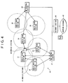
- the mobile station 40 is positioned in the neighborhood of the radio base station 31 while the mobile station 41 is positioned in the neighborhood of the radio base station 32.
- the mobile stations 40 and 41 receive an extrapolation pilot signal transmitted from the radio base station 31 and receive data transmitted from the radio base station 1 using the extrapolation pilot signal.
- a communication channel between the radio base station 32 and the mobile station 40 or 41 itself is recognized as noise to the extrapolation pilot signal of the radio base station 31.
- the two mobile stations 40 and 41 receive the same service (for example, voice communication, non-limit digital communication, packet communication or the like) , then it is necessary that a constant error rate be assured. If the error rate exceeds a level therefor, then substantial deterioration of sound quality, congestion of a packet communication system or the like occurs.
- the same service for example, voice communication, non-limit digital communication, packet communication or the like
- FIG. 5 is a diagrammatic view illustrating interference with an extrapolation pilot signal described above.
- the radio base station 31 transmits an extrapolation pilot signal with the 10 dBm level.
- the propagation losses of the extrapolation pilot signal to the mobile station 40 and the mobile station 41 are -70dB and -90dB, respectively.
- the mobile station 41 is positioned farther by a distance corresponding to 20dB than the mobile station 40 from the radio base station 31.
- the influence of the interference (another station interference) wave from the radio base station 32 is equivalent to -10dB with the mobile station 40, and is equivalent to -20dB with the mobile station 41.
- the mobile station 41 is positioned nearer by a distance corresponding to 10dB than the mobile station 40 from the radio base station 32.
- the transmission level Tx_DCH1 of the communication channel (DCH1) from the radio base station 31 to the mobile station 40 is -10 dBm and the transmission level Tx_DCH2 of the communication channel (DCH2) from the radio base station 31 to the mobile station 41 is +20 dBm.
- the transmission levels of the communication channels DCH1 and DCH2 in the radio base station 31 are controlled to - 10 dBm and +20 dBm, respectively, by the TPC.
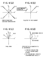
- pilot signals can be collected to one point as seen in FIG. 6(b) if fixed rotation processing (polar coordinate calculation) is performed for them.
- the received vectors are rotated by carrier deviation between the ratio base station and the mobile station and fluctuation of the delay amount in the propagation path.
- ⁇ ⁇ move + ⁇ error
- ⁇ move represents the phase variation by the temperature/fading/multi-paths and so forth
- ⁇ error represents the phase variation by the carrier frequency deviation between the radio base station and the mobile station
- (Ri, Rq) represents the reception vector
- (Di, Dq) represents the actual signal vector
- FIG. 6(d) A variation of a vector signal when interference is superposed on a pilot signal is illustrated in FIG. 6(d). Where the interference is random, the intersecting point is dispersed within such a range as indicated by a middle point line A of FIG. 6(d) , and the rotation amount cannot be measured precisely.
- both of the extrapolation pilot signal and the interpolation pilot signal are used as pilot signals for use for estimation of a phase rotation amount.
- the channel estimation apparatus 23 estimates the phase rotation amount in accordance with the expression (1) given hereinabove, the precision in estimation of the phase rotation amount can be improved and the stability can be assured without depending upon conditions of the TPC, and a good reception sensitivity is assured as the reception sensitivity after the phase correction.
- the phase correction sections 27-1 to 27-3 perform phase correction of the signals of the communication channels despread by the despreading sections 26-1 to 26-3, respectively, using the phase rotation amounts estimated by the channel estimation apparatus 23 to perform delay adjustment and then Rake combine the signals.
- the RSCP/SIR measurement section 23e measures the reception level and the SIR (ratio between the desired wave intensity of the extrapolation pilot signal and the interference wave intensity of the demodulated extrapolation pilot signal) using the extrapolation pilot signal demodulated by the complex calculation section 23a described above.
- the RSCP/SIR measurement section 23f measures the reception level and the SIR using the interpolation pilot signal demodulated by the complex calculation section 23b.
- the level of a communication channel is normally varied by transmission power control, and also the interference amount from the communication channel itself of the mobile communication terminal itself varies depending upon the situation. Also in the channel estimation apparatus 23, the parameters of the expression (1) are modified in accordance with the situations of the demodulated extrapolation pilot signal and interpolation pilot signal to improve the characteristic.
- phase rotation amount estimated in this manner is used to perform phase correction to place the reception sensitivity into an optimum condition.
- both of an extrapolation pilot signal and an interpolation pilot signal are used as pilot signals for use for estimation of a phase rotation amount to reduce the influence of interference upon the extrapolation pilot signal. Consequently, not only the precision in channel estimation (estimation of a phase rotation amount) can be improved and the stability can be assured, but also a good reception sensitivity after phase correction can be assured. As a result, the transmission power control can be optimized, and the transmission level of the radio base station can be lowered thereby to increase the system capacity.
- the mobile communication terminal of the present invention can be applied not only to a system according to the embodiment described above but also to a base band reception system of the known CDMA system which adopts both of an extrapolation pilot signal and an interpolation pilot signal.
- the channel estimation apparatus 23 in the embodiment described above uses the expression (1) to estimate a phase rotation amount
- the estimation of a phase rotation amount is not limited to this, and a phase rotation amount may be estimated otherwise by merely changing over between a demodulated extrapolation signal and a demodulated interpolation pilot signal across a boundary of an SIR, a reception level or the like.
- the two pilot signals can be compared with each other to use the one which has a better characteristic to perform synchronous detection.
- the channel estimation apparatus 23 described above uses a combination of a reception level and an SIR as reception quality index values (a first reception quality index value and a second reception quality index value)
- the configuration of the channel estimation apparatus 23 is not limited to this, but the controller 23g may otherwise be configured such that it uses a single reception quality index value to set a distribution ratio parameter described hereinabove. Also in this instance, similar advantages to those of the embodiment described above can be achieved.
- the first and second reception equality measurement sections as function sections denoted by reference characters 23e and 23f in FIG. 1 may be configured as a function section which measures only a single kind of reception quality index value, and the controller 23g may use a reference table which stores distribution ratio parameters based on the single kind of reception quality index value.
- reception quality index value in addition to a reception level of a demodulated pilot signal, for example, an SIR, a signal to noise ratio (Eb/Io) in a unit of a bit, or a calculation value of the number of errors of demodulated extrapolation pilot signal and interpolation pilot signal.
- a reception level of a demodulated pilot signal for example, an SIR, a signal to noise ratio (Eb/Io) in a unit of a bit, or a calculation value of the number of errors of demodulated extrapolation pilot signal and interpolation pilot signal.
- Eb/Io signal to noise ratio
- comparison margin value in the embodiment described above may be set as an absolute value (for example, a decibel value where the reception level is used as the reception quality index value), also an alternative configuration wherein substantially no margin value is used (0 dB) is possible. This similarly applies also where any other value than the reception level is used as the reception quality index value.
- the estimation value selection logic section 23h sets the distribution ratio parameters so that, when the reception quality index value from the RSCP/SIR measurement section 23e is higher than the reception quality index value from the RSCP/SIR measurement section 23f, the channel estimation value from the channel estimation section 23c may be outputted as a phase correction amount, but when the reception quality index value from the RSCP/SIR measurement section 23e is lower than the reception quality index value from the RSCR/SIR measurement section 23f, the channel estimation value from the channel estimation section 23d may be outputted as a phase correction amount.
- the present invention can naturally be applied also to a mobile communication terminal to which a communication system other than the CDMA communication system is applied.
Landscapes
- Engineering & Computer Science (AREA)
- Computer Networks & Wireless Communication (AREA)
- Signal Processing (AREA)
- Power Engineering (AREA)
- Mobile Radio Communication Systems (AREA)
Applications Claiming Priority (3)
| Application Number | Priority Date | Filing Date | Title |
|---|---|---|---|
| JP2001264603A JP4448633B2 (ja) | 2001-08-31 | 2001-08-31 | 移動体通信端末 |
| JP2001264603 | 2001-08-31 | ||
| EP20020251943 EP1289216B1 (de) | 2001-08-31 | 2002-03-19 | Vorrichtung zur Phasenkorrektur in einem CDMA System mittels sowohl eines kontinuierlichen als auch eines intermittierenden Piloten mit jeweils unterschiedlichen Spreizkodes |
Related Parent Applications (1)
| Application Number | Title | Priority Date | Filing Date |
|---|---|---|---|
| EP20020251943 Division EP1289216B1 (de) | 2001-08-31 | 2002-03-19 | Vorrichtung zur Phasenkorrektur in einem CDMA System mittels sowohl eines kontinuierlichen als auch eines intermittierenden Piloten mit jeweils unterschiedlichen Spreizkodes |
Publications (2)
| Publication Number | Publication Date |
|---|---|
| EP1455497A2 true EP1455497A2 (de) | 2004-09-08 |
| EP1455497A3 EP1455497A3 (de) | 2004-09-15 |
Family
ID=19091179
Family Applications (2)
| Application Number | Title | Priority Date | Filing Date |
|---|---|---|---|
| EP20040012439 Ceased EP1455497A3 (de) | 2001-08-31 | 2002-03-19 | Mobiles Kommunikationsendgerät welches sowohl ein kontinuierliches als auch ein intermittierendes Pilotsignal zur Kanalschätzung verwendet |
| EP20020251943 Expired - Lifetime EP1289216B1 (de) | 2001-08-31 | 2002-03-19 | Vorrichtung zur Phasenkorrektur in einem CDMA System mittels sowohl eines kontinuierlichen als auch eines intermittierenden Piloten mit jeweils unterschiedlichen Spreizkodes |
Family Applications After (1)
| Application Number | Title | Priority Date | Filing Date |
|---|---|---|---|
| EP20020251943 Expired - Lifetime EP1289216B1 (de) | 2001-08-31 | 2002-03-19 | Vorrichtung zur Phasenkorrektur in einem CDMA System mittels sowohl eines kontinuierlichen als auch eines intermittierenden Piloten mit jeweils unterschiedlichen Spreizkodes |
Country Status (4)
| Country | Link |
|---|---|
| US (1) | US7421010B2 (de) |
| EP (2) | EP1455497A3 (de) |
| JP (1) | JP4448633B2 (de) |
| DE (1) | DE60202914T2 (de) |
Families Citing this family (18)
| Publication number | Priority date | Publication date | Assignee | Title |
|---|---|---|---|---|
| US7263082B1 (en) * | 2002-06-28 | 2007-08-28 | Arraycomm, Llc | Resolving user-specific narrow beam signals using a known sequence in a wireless communications system with a common pilot channel |
| WO2004080011A1 (en) * | 2003-03-03 | 2004-09-16 | Matsushita Electric Industrial Co., Ltd. | Mobile terminal having functions of program reception through broadcasting and through network communication, and program reception controlling method |
| US20050272373A1 (en) * | 2003-06-04 | 2005-12-08 | Matsushita Electric Industrial Co., Ltd | Sir measurement device and sir measurement method |
| US8724447B2 (en) | 2004-01-28 | 2014-05-13 | Qualcomm Incorporated | Timing estimation in an OFDM receiver |
| US8433005B2 (en) | 2004-01-28 | 2013-04-30 | Qualcomm Incorporated | Frame synchronization and initial symbol timing acquisition system and method |
| JP4193900B2 (ja) * | 2004-02-27 | 2008-12-10 | 日本電気株式会社 | Cdma受信装置および方法 |
| JP4448403B2 (ja) * | 2004-08-16 | 2010-04-07 | 富士通株式会社 | 電力レベル測定装置及び移動局 |
| CN101204016B (zh) * | 2005-05-23 | 2013-02-13 | 思科技术公司 | 用于干扰减少的方法和系统 |
| JP4226641B2 (ja) * | 2005-07-27 | 2009-02-18 | 三菱電機株式会社 | Sir検出装置および無線通信装置 |
| JP2009139093A (ja) * | 2007-12-03 | 2009-06-25 | Seiko Epson Corp | マルチパス信号判定方法、信号適否判定方法、測位演算方法、プログラム及びマルチパス信号判定回路 |
| WO2009084091A1 (ja) * | 2007-12-27 | 2009-07-09 | Fujitsu Limited | 送信電力制御方法及びその装置 |
| CA2806510C (en) * | 2010-08-12 | 2017-01-03 | Fujitsu Limited | Communication setting method, wireless base station, and mobile station |
| CN102148779B (zh) * | 2011-03-21 | 2013-07-24 | 电信科学技术研究院 | 一种信号检测的方法及装置 |
| US10003377B1 (en) | 2016-12-19 | 2018-06-19 | Cisco Technology, Inc. | Spread spectrum acoustic communication techniques |
| US10141973B1 (en) | 2017-06-23 | 2018-11-27 | Cisco Technology, Inc. | Endpoint proximity pairing using acoustic spread spectrum token exchange and ranging information |
| US10404319B1 (en) | 2018-07-09 | 2019-09-03 | Cisco Technology, Inc. | Fast correlation of prometheus orthonormal sets (PONS) for communications |
| US10396846B1 (en) | 2018-10-12 | 2019-08-27 | Cisco Technology, Inc. | Adaptive decoding of spread spectrum signals using multiple correlator peaks |
| US10601459B1 (en) | 2018-11-02 | 2020-03-24 | Cisco Technology, Inc. | Efficient handling of clock offset in spread spectrum decoders |
Family Cites Families (11)
| Publication number | Priority date | Publication date | Assignee | Title |
|---|---|---|---|---|
| EP0715440B1 (de) * | 1994-06-22 | 2004-06-16 | NTT DoCoMo, Inc. | Synchrondetektorschaltung und synchronisierungsmethode für einen digitalsignalempfänger |
| JP2934185B2 (ja) * | 1996-03-15 | 1999-08-16 | 松下電器産業株式会社 | Cdmaセルラ無線基地局装置および移動局装置および送信方法 |
| JP3006679B2 (ja) * | 1997-01-16 | 2000-02-07 | 日本電気株式会社 | セルラー移動電話システム |
| JP3029031B2 (ja) * | 1998-09-03 | 2000-04-04 | 日本電気株式会社 | 内挿同期検波方法と無線通信システム |
| US6363102B1 (en) * | 1999-04-23 | 2002-03-26 | Qualcomm Incorporated | Method and apparatus for frequency offset correction |
| US6414988B1 (en) * | 1999-05-12 | 2002-07-02 | Qualcomm Incorporated | Amplitude and phase estimation method in a wireless communication system |
| EP1065800A1 (de) * | 1999-07-02 | 2001-01-03 | Lucent Technologies Inc. | CDMA-System mit verbesserten Pilot-Kanälen |
| US6611675B1 (en) * | 2000-09-26 | 2003-08-26 | Nokia Mobile Phone Ltd. | Antenna verification method for advanced closed loop mode-one transmitter antenna diversity |
| US6775340B1 (en) * | 2000-10-13 | 2004-08-10 | Ericsson Inc. | Synchronization and channel estimation with extended pilot symbols |
| US6680727B2 (en) * | 2000-10-17 | 2004-01-20 | Qualcomm Incorporated | Method and apparatus for canceling pilot interference in a CDMA communication system |
| US8290098B2 (en) * | 2001-03-30 | 2012-10-16 | Texas Instruments Incorporated | Closed loop multiple transmit, multiple receive antenna wireless communication system |
-
2001
- 2001-08-31 JP JP2001264603A patent/JP4448633B2/ja not_active Expired - Fee Related
-
2002
- 2002-03-19 DE DE2002602914 patent/DE60202914T2/de not_active Expired - Lifetime
- 2002-03-19 EP EP20040012439 patent/EP1455497A3/de not_active Ceased
- 2002-03-19 EP EP20020251943 patent/EP1289216B1/de not_active Expired - Lifetime
- 2002-03-26 US US10/107,272 patent/US7421010B2/en not_active Expired - Fee Related
Also Published As
| Publication number | Publication date |
|---|---|
| US20030043775A1 (en) | 2003-03-06 |
| DE60202914T2 (de) | 2005-07-21 |
| EP1289216A1 (de) | 2003-03-05 |
| JP4448633B2 (ja) | 2010-04-14 |
| DE60202914D1 (de) | 2005-03-17 |
| US7421010B2 (en) | 2008-09-02 |
| EP1455497A3 (de) | 2004-09-15 |
| JP2003078959A (ja) | 2003-03-14 |
| EP1289216B1 (de) | 2005-02-09 |
Similar Documents
| Publication | Publication Date | Title |
|---|---|---|
| EP1349294B1 (de) | Gewichtete Leistungsregelung in offener Schleife in einem Zeitduplexkommunikationssystem | |
| US7532659B2 (en) | Weighted open loop power control transmitter cross reference to related applications | |
| EP1455497A2 (de) | Mobiles Kommunikationsendgerät welches sowohl ein kontinuierliches als auch ein intermittierendes Pilotsignal zur Kanalschätzung verwendet | |
| JP3461124B2 (ja) | 干渉信号電力測定方法 | |
| EP1001558A2 (de) | Übertragungsendgerät und Funkübertragungsverfahren mit Sendesdiversität | |
| KR20010075015A (ko) | 전력 제어 비트를 사용하여 부호 분할 다중 액세스시스템에서의 채널 추정 | |
| US20020034216A1 (en) | CDMA receiving apparatus with transmission power control using previous SIR value | |
| HK1061476B (en) | Weighted open loop power control in a time division duplex communication system | |
| HK1085857B (en) | Weighted open loop power control in a time division duplex communication system |
Legal Events
| Date | Code | Title | Description |
|---|---|---|---|
| PUAI | Public reference made under article 153(3) epc to a published international application that has entered the european phase |
Free format text: ORIGINAL CODE: 0009012 |
|
| PUAL | Search report despatched |
Free format text: ORIGINAL CODE: 0009013 |
|
| AC | Divisional application: reference to earlier application |
Ref document number: 1289216 Country of ref document: EP Kind code of ref document: P |
|
| AK | Designated contracting states |
Kind code of ref document: A2 Designated state(s): DE FR GB |
|
| AK | Designated contracting states |
Kind code of ref document: A3 Designated state(s): DE FR GB |
|
| 17P | Request for examination filed |
Effective date: 20041213 |
|
| AKX | Designation fees paid |
Designated state(s): DE FR GB |
|
| 17Q | First examination report despatched |
Effective date: 20070402 |
|
| STAA | Information on the status of an ep patent application or granted ep patent |
Free format text: STATUS: THE APPLICATION HAS BEEN REFUSED |
|
| 18R | Application refused |
Effective date: 20101130 |