EP1455870B1 - Medizinische abgabevorrichtung - Google Patents
Medizinische abgabevorrichtung Download PDFInfo
- Publication number
- EP1455870B1 EP1455870B1 EP02781170A EP02781170A EP1455870B1 EP 1455870 B1 EP1455870 B1 EP 1455870B1 EP 02781170 A EP02781170 A EP 02781170A EP 02781170 A EP02781170 A EP 02781170A EP 1455870 B1 EP1455870 B1 EP 1455870B1
- Authority
- EP
- European Patent Office
- Prior art keywords
- plunger
- spherical
- flexible
- plunger rod
- flexible plunger
- Prior art date
- Legal status (The legal status is an assumption and is not a legal conclusion. Google has not performed a legal analysis and makes no representation as to the accuracy of the status listed.)
- Expired - Lifetime
Links
- 239000003814 drug Substances 0.000 claims description 26
- 239000012530 fluid Substances 0.000 claims description 9
- 239000012528 membrane Substances 0.000 claims description 6
- 239000007788 liquid Substances 0.000 claims 3
- 238000007373 indentation Methods 0.000 description 10
- 238000001802 infusion Methods 0.000 description 5
- 238000002347 injection Methods 0.000 description 5
- 239000007924 injection Substances 0.000 description 5
- 241000124008 Mammalia Species 0.000 description 4
- 229940079593 drug Drugs 0.000 description 4
- 210000001981 hip bone Anatomy 0.000 description 3
- 230000005484 gravity Effects 0.000 description 2
- 229940071643 prefilled syringe Drugs 0.000 description 2
- 210000004204 blood vessel Anatomy 0.000 description 1
- 239000011521 glass Substances 0.000 description 1
- 239000000463 material Substances 0.000 description 1
- 238000000034 method Methods 0.000 description 1
- 239000000203 mixture Substances 0.000 description 1
- 230000000149 penetrating effect Effects 0.000 description 1
- 230000002035 prolonged effect Effects 0.000 description 1
- 239000012858 resilient material Substances 0.000 description 1
- 238000007789 sealing Methods 0.000 description 1
- 239000000243 solution Substances 0.000 description 1
Images




Classifications
-
- A—HUMAN NECESSITIES
- A61—MEDICAL OR VETERINARY SCIENCE; HYGIENE
- A61M—DEVICES FOR INTRODUCING MEDIA INTO, OR ONTO, THE BODY; DEVICES FOR TRANSDUCING BODY MEDIA OR FOR TAKING MEDIA FROM THE BODY; DEVICES FOR PRODUCING OR ENDING SLEEP OR STUPOR
- A61M5/00—Devices for bringing media into the body in a subcutaneous, intra-vascular or intramuscular way; Accessories therefor, e.g. filling or cleaning devices, arm-rests
- A61M5/178—Syringes
- A61M5/31—Details
- A61M5/315—Pistons; Piston-rods; Guiding, blocking or restricting the movement of the rod or piston; Appliances on the rod for facilitating dosing ; Dosing mechanisms
- A61M5/31511—Piston or piston-rod constructions, e.g. connection of piston with piston-rod
-
- A—HUMAN NECESSITIES
- A61—MEDICAL OR VETERINARY SCIENCE; HYGIENE
- A61M—DEVICES FOR INTRODUCING MEDIA INTO, OR ONTO, THE BODY; DEVICES FOR TRANSDUCING BODY MEDIA OR FOR TAKING MEDIA FROM THE BODY; DEVICES FOR PRODUCING OR ENDING SLEEP OR STUPOR
- A61M5/00—Devices for bringing media into the body in a subcutaneous, intra-vascular or intramuscular way; Accessories therefor, e.g. filling or cleaning devices, arm-rests
- A61M5/178—Syringes
- A61M5/31—Details
- A61M5/315—Pistons; Piston-rods; Guiding, blocking or restricting the movement of the rod or piston; Appliances on the rod for facilitating dosing ; Dosing mechanisms
- A61M5/31511—Piston or piston-rod constructions, e.g. connection of piston with piston-rod
- A61M5/31515—Connection of piston with piston rod
Definitions
- the invention relates to a medication delivery device for delivering medicine or other fluent material into a mammal body, and especially to a medication delivery device where a plunger located in a tubular cartridge is connected to a plunger rod.
- Medication delivery devices are widely used throughout the health sector for delivering fluent medicine into mammal bodies through a conduit inserted in the body.
- the first type being an injection device, which injects a predetermined dose of the fluent medicine into a mammal body whenever the injection device is activated.
- the other type being an infusion device, which delivers a constant rate of medicine into a mammal body either by gravity or by pressure, which pressure are usually generated by an electrical motor.
- the fluent medicine is usually contained in a cartridge, which can be either a fillable cartridge or a pre-filled disposable cartridge.
- a cartridge which can be either a fillable cartridge or a pre-filled disposable cartridge.
- Such known cartridges are e.g. provided as a cylindrical barrel having a penetrable membrane at a distal end and a movable plunger at the opposite proximal end. A conduit penetrating the membrane is mounted at the distal end.
- Some infusions pumps available today have a fillable cartridge, which are filled with the medicament prior to use.
- Such fillable cartridge usually has a plunger having the back wall provided with an interior thread into which a pull rod is screwed. The plunger can then be moved backwards inside the fillable cartridge, and the cartridge can be filled with medicine from a vial. Once the reusable cartridge has been filled, the plunger is disconnected from the pull rod and connected to the pump plunger rod. The assembled cartridge and plunger rod are then inserted into the infusion pump.
- the plunger rod is not located at the centre of the plunger, the plunger might tilt once the plunger rod is connected with the plunger rod. When the plunger tilts the sealing between the cartridge wall and the plunger will become leaky.
- auxiliary part such as Velcro tape, a magnet or a ball and socket connection at the centre of the plunger. This will ensure that the plunger rod will always connect the plunger at the centre. It is however rather cumbersome from a manufactures point of view and will give rise to a number of failures if the auxiliary part has been disconnected from the plunger prior to use.
- pre-filled cartridges When using pre-filled cartridges, it would be preferred if the same pre-filled cartridge can be used both for pump systems and for traditional pen syringes. In pen syringes there are however no connection between the plunger and the plunger rod. Usually the plunger rod has a somewhat flat end, which abuts the plunger. If auxiliary parts are permanently mounted on the plunger, it will be impossible to use the cartridge in an ordinary pen syringe.
- US 5.928.202 An infusion system into which a pre-filled syringe is mounted is disclosed in US 5.928.202 .
- the plunger rod shown in this system is at the distal end provided with a ball-shaped portion and the plunger is provided with a spherical cavity into which the ball-shaped portion can be loaded.
- the channel of the pre-filled syringe has at the proximal end a funnel-shaped part, which closes the cavity of the plunger around the ball-shaped portion of the plunger rod as the plunger rod is advanced forward.
- the presence of the funnel-shaped part makes it impracticable to use this solution for a glass cartridge, since these are normally produced with a constant inside diameter, thus it is generally considered an inconvenience to have an uneven outer diameter on a cartridge.
- the design disclosed in US 5.928.202 does not allow plunger rod disconnection when the plunger is located outside the funnel-shaped zone, and the size of the disconnection force is depended on the exact position of the plunger in the funnel
- the plunger with an interior cavity engaged by a spherical or semi spherical portion of the plunger rod.
- the spherical shaped portion is provided with indentations.
- connection can be connected and disconnected using only a limited amount of force, because the indentations allow air in the plunger cavity to escape during plunger rod connection thereby avoiding a counteract pressure build up.
- the same situation occurs during disconnection as air need to pass through the indentations to avoid counteract under pressure i.e. vacuum in the plunger cavity.
- the diameter of a circular orifice or the minimum cross section of a non-circular orifice has the same diameter as the spherical or semi spherical shaped portion of the plunger rod, a connection, which is very easy to disconnect, is obtained. If however the diameter of the spherical or semi spherical shaped portion of the plunger rod is larger than the minimum cross section or diameter of the open orifice of the plunger as specified in claim 2, the connection will be somewhat tighter.
- a suitable disconnectable grip is possible if the outside diameter of the spherical or semi spherical shaped end portion of the plunger rod and the inside diameter of the interior cavity is approximately between 3 to 7 mm and preferably around 5 to 6 mm for a cartridge of 9 to 11 mm, while the diameter of the open orifice should be approximately between 3,5 to 7, mm, preferably around 4 to 5 mm.
- the indentations are preferably made such that the spherical or semi spherical shaped portion of the plunger rod has a cross-shaped cross section perpendicular to the longitudinal axis of the plunger rod, as disclosed in claim 3. This provides a suitable connection between the plunger rod and the plunger, where the force needed to disconnect the two parts are determined by the width of the arms of the cross in combination with the diameter of the cross and of the open orifice.
- bulging of a flexible plunger gives rise to either back suction or after drip when the plunger returns to its initiate form after it has been compressed, bulging should be avoided.
- the point of contact between the plunger rod and the plunger should be located as close to the front wall of the plunger as possible.
- the plunger rod is easier guided into the open orifice if the most distal end of the plunger rod has the shape of a spherical cap such as indicated in claim 4.
- the open orifice can be made circular with protrusions, as specified in claim 6. This will also allow air to escape from the cavity during connection, and air to pass into the cavity during disconnection.
- the circular cross section of the open orifice has a diameter substantially equal to or larger than the diameter of the spherical or semi spherical shaped portion of the plunger rod and the cross section formed between the protrusions are smaller than the diameter of the spherical or semi spherical shaped portion of the plunger rod it is ensured that the connection is easy disconnectable.
- the open orifice could also be provided with a non-circular cross section as specified in claim 9, as this will also allow air to escape from the cavity during connection, and air to pass into the cavity during disconnection.
- the minimum cross section of the open non-circular orifice should be substantially the same or smaller than the diameter of the spherical or semi spherical portion of the plunger rod, such as cited in claim 10.
- the term "semi spherical” is used to describe an object such as a cavity or an end portion of a plunger having a three-dimensional geometry where at least a part of the surfaces has the shape of a spherical cap.
- distal end is meant to refer to the end of cartridge where the fluid medicament is contained and where the conduit is inserted
- proximal end is meant to refer to the opposite end where the plunger is located in its initial position
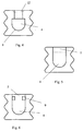
- Figure 1-6 shows different embodiments of a plunger 1 as seen from the side.
- the plunger 1 illustrated in figure 1 has a front wall 2, which is in contact with the fluid medicament inside the cartridge and an opposite located back wall 3. Encapsulated in the interior of the plunger 1 is a spherical cavity 4 provided. This cavity 4 is connected to the back wall 3 through an open orifice 5.
- the cavity 4 is prolonged in the distal direction with an additional cylindrical appendix 6.
- the cavity 4 shown in figure 3 has only a semi spherical shape, as the proximal end 7 of the cavity 4 has the shape of a spherical cap, while the distal end of the cavity has a cylindrical form.
- Figure 4 also shows a semi spherical cavity 4 having the shape of a spherical cap at the distal end 8, while the proximal end has a cylindrical shape.
- the proximal end of the open orifice 5 could be provided with an inlet 22, which makes it easier to load the plunger rod 6 into the open orifice 5.
- the plunger illustrated in figure 5 has a cavity 4 similar to the cavity 4 shown in figure 4, however the open orifice has a diameter equal to the diameter of both the cylindrical part and the spherical cap part.
- the open orifice 5 could be provided with protrusions 9 as illustrated in figure 6.
- the number and size of the protrusions 9 can be chosen randomly in order to provide the grip needed for a particular injection or infusion system.
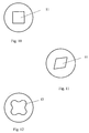
- Figure 7 shows a top view of a plunger with two such protrusions 9, and figure 8 shows a plunger with four protrusions 9.
- the open orifice 5 could have a substantially circular cross section 10 as shown in figure 9, or the cross section could be four-sided 11 as shown in figure 10 and figure 11.
- the non-circular cross section of the open orifice 5 could in fact be any kind of polygon 12 as indicated in figure 12, or even any other shape e.g. shaped like a four-leaf.
- the plunger rod 6 of the connection is shown in figure 13-20.
- a hipbone connection is established. Due to this hipbone connection a plunger rod 6 with a diameter substantially smaller than the diameter of the cartridge can be used without tilting the plunger 1 if the plunger rod 6 is pressed towards the side of the cartridge.
- the plunger 1 and the plunger rod 13 are connected in a stiff or permanent connection, the plunger might tilt and cause leakage if the plunger rod 13 is not kept in the centre of the cartridge, a hipbone connection however solves this problem.
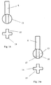
- Figure 13 illustrates a plunger rod 6 with a spherical shaped end portion 13 located at the distal end of the plunger rod 6.
- this spherical shaped portion 13 is preferably provided with tracks, slots, apertures or similar indentations as illustrated in figure 14-18.
- the spherical shaped end portion 13 of the plunger rod 6 has a cross-shaped cross section when viewed perpendicular to the longitudinal axis of the plunger rod 6.
- the cross 14 has four arms, which arms each abuts the imaginary diameter of the spherical end portion 13.
- the space 15 between the arms can off cause vary in size, which is also the case for the number of arms.
- figure 14 and figure 14a shows a schematic view of the cross section of the spherical part 13.
- the space 15 needs not extend through the full longitudinal diameter of the spherical shaped portion 13, but could end at a line 16 leaving a spherical cap 17 at the most distal end of the spherical end portion 13, as shown in figure 14a.
- plunger rods 6 A number of different plunger rods 6 are disclosed in figure 15-17. These plunger rods 6 has a spherical portion 13 at the distal end with indentations 18. These indentations all leave a spherical cap 17 at the most distal end of the plunger rod 6.
- Figure 18 shows a plunger rod 6 where the spherical portion 13 is provided with indentations leaving a spherical cap 17 at the proximal end of the spherical end portion 13
- the distal end of the plunger rod 6 could also, as shown in figure 19, be provided with a semi spherical end portion 19 which could be provided with outwardly pointing protrusions 20 in order to enhance the grip.
- Such protrusions 20 could also be provided at the spherical end portion 13 of the plunger rod 6 as shown in figure 20.
- Figure 21 shows a plunger rod 6 with a spherical end portion 13 having two slots 21.
- a schematic view of the cross section of the spherical part 13 is also included.
Landscapes
- Health & Medical Sciences (AREA)
- Vascular Medicine (AREA)
- Engineering & Computer Science (AREA)
- Anesthesiology (AREA)
- Biomedical Technology (AREA)
- Heart & Thoracic Surgery (AREA)
- Hematology (AREA)
- Life Sciences & Earth Sciences (AREA)
- Animal Behavior & Ethology (AREA)
- General Health & Medical Sciences (AREA)
- Public Health (AREA)
- Veterinary Medicine (AREA)
- Infusion, Injection, And Reservoir Apparatuses (AREA)
- Ultra Sonic Daignosis Equipment (AREA)
Claims (11)
- Medikamentenabgabesystem, umfassend:eine Patrone mit einem durch eine flexible Membran verschlossenen entfernten Ende und einem nahen Ende, das durch eine Wand verbunden ist, die ein flüssiges Arzneimittel enthaltendes Gefäß bildet,einen flexiblen Kolben (1), der im nahen Ende des Gefäßes aufgenommen ist und entlang des Gefäßes bewegt wird, um das flüssige Medikament auszustoßen, wobei der flexible Kolben (1) eine Vorderwand (2) in Kontakt mit dem flüssigen Medikament und eine gegenüber liegende Rückwand (3) aufweist, wobei die Rückwand (3) mit einem kugelförmig oder halbkugelförmig gestalteten Hohlraum (4) vollständig im Inneren des flexiblen Kolbens (1) eingekapselt bereitgestellt und mit der Rückwand (3) des flexiblen Kolbens (1) durch eine offene Öffnung (5) verbunden ist,eine Kolbenstange (6) die vorwärts in das Gefäß bewegt werden kann, um den flexiblen Kolben (1) vorwärts zu bewegen, und wobei die Kolbenstange (6) mit dem flexiblen Kolben (1) trennbar verbunden ist,wobei die trennbare Verbindung zwischen dem flexiblen Kolben (1) und der Kolbenstange (6) durch einen am entfernten Ende der Kolbenstange (6) bereitgestellten kugelförmigen oder halbkugelförmigen Teil (13, 19) erhalten wird, der mit dem kugelförmig oder halbkugelförmig gestalteten Hohlraum (4) des flexiblen Kolbens (1) in Eingriff steht,
dadurch gekennzeichnet, dass
der kugelförmig oder halbkugelförmig gestaltete Teil (13, 19) mit Bahnen, Schlitzen oder Ausschnitten (15, 18, 21) bereitgestellt ist, die es ermöglichen, dass Luft während des Verbindens entweicht. - Medikamentenabgabesystem nach Anspruch 1, dadurch gekennzeichnet, dass der Durchmesser des kugelförmig oder halbkugelförmig gestalteten Teils (13, 19) der Kolbenstange (6) größer ist als der Mindestquerschnitt oder -durchmesser der offenen Öffnung (5) des flexiblen Kolbens (1).
- Medikamentenabgabesystem nach Anspruch 1 oder 2, dadurch gekennzeichnet, dass der kugelförmig oder halbkugelförmig gestaltete Teil (13, 19) einen zur Längsachse der Kolbenstange (6) senkrechten kreuzförmigen Querschnitt aufweist.
- Medikamentenabgabesystem nach einem der Ansprüche 1 bis 3, dadurch gekennzeichnet, dass das am weitesten entfernte Ende des kugelförmig oder halbkugelförmig gestalteten Teils (13, 19) die Gestalt einer kugelförmigen Kappe (17) aufweist.
- Verbindung zwischen einem flexiblen Kolben (1) und einer Kolbenstange (6), die in Kombination umfassen:einen flexiblen Kolben (1) mit einer Vorderwand (2) und einer Rückwand (3), wobei der flexible Kolben (1) einen mit der Rückwand (3) durch eine offene Öffnung (5) verbundenen inneren kugelförmig oder halbkugelförmig gestalteten Hohlraum (4) aufweist,eine Kolbenstange (6) mit einem kugelförmig oder halbkugelförmig gestalteten Endteil (13, 19), wobei der Endteil (13, 19) trennbar mit dem Hohlraum (4) des flexiblen Kolbens (1) in Eingriff steht, so dass sich der flexible Kolben (1) und die Kolbenstange (6) gemeinsam bewegen,dadurch gekennzeichnet, dass der kugelförmig oder halbkugelförmig gestaltete Endteil (13, 19) der Kolbenstange (6) mit Bahnen, Schlitzen oder Ausschnitten (15, 18, 21) bereitgestellt ist, die es ermöglichen, dass Luft während des Verbindens entweicht.
- Medikamentenabgabesystem, umfassend:eine Patrone mit einem durch eine flexible Membran verschlossenen entfernten Ende und einem nahen Ende, das durch eine Wand verbunden ist, die ein ein flüssiges Arzneimittel enthaltendes Gefäß bildet,einen flexiblen Kolben (1), der im nahen Ende des Gefäßes aufgenommen ist und entlang des Gefäßes bewegt wird, um das flüssige Medikament auszustoßen, wobei der flexible Kolben (1) eine Vorderwand (2) in Kontakt mit dem flüssigen Medikament und eine gegenüber liegende Rückwand (3) aufweist, wobei die Rückwand (3) mit einem kugelförmig oder halbkugelförmig gestalteten Hohlraum (4) vollständig im Inneren des flexiblen Kolbens (1) eingekapselt bereitgestellt und mit der Rückwand (3) des flexiblen Kolbens (1) durch eine offene Öffnung (5) verbunden ist,eine Kolbenstange (6) die vorwärts in das Gefäß bewegt werden kann, um den flexiblen Kolben (1) vorwärts zu bewegen, und wobei Kolbenstange (6) mit dem flexiblen Kolben (1) trennbar verbunden ist,wobei die trennbare Verbindung zwischen dem flexiblen Kolben (1) und der Kolbenstange (6) durch einen am entfernten Ende der Kolbenstange (6) bereitgestellten kugelförmigen oder halbkugelförmigen Teil (13, 19) erhalten wird, der mit dem kugelförmig oder halbkugelförmig gestalteten Hohlraum (4) des flexiblen Kolbens (1) in Eingriff steht,
dadurch gekennzeichnet, dass die offene Öffnung (5) einen mit Vorsprüngen bereitgestellten im Wesentlichen kreisförmigen Querschnitt (10) aufweist, der es ermöglicht, dass Luft während des Verbindens entweicht. - Medikamentenabgabesystem nach Anspruch 6, dadurch gekennzeichnet, dass der kreisförmige Querschnitt der offenen Öffnung (5) einen Durchmesser aufweist, der gleich oder größer als der Durchmesser des kugelförmig oder halbkugelförmig gestalteten Teils (13) der Kolbenstange (6) ist, und dass der zwischen den Vorsprüngen (9) gestaltete Querschnitt kleiner als der Durchmesser des kugelförmig oder halbkugelförmig gestalteten Teils (13) der Kolbenstange (6) ist.
- Verbindung zwischen einem flexiblen Kolben (1) und einer Kolbenstange (6), die in Kombination umfassen:einen flexiblen Kolben (1) mit einer Vorderwand (2) und einer Rückwand (3), wobei der flexible Kolben (1) einen mit der Rückwand (3) durch eine offene Öffnung (5) verbundenen inneren kugelförmig oder halbkugelförmig gestalteten Hohlraum (4) aufweist,eine Kolbenstange (6) mit einem kugelförmig oder halbkugelförmig gestalteten Endteil (13, 19), wobei Endteil (13, 19) trennbar mit dem Hohlraum (4) des flexiblen Kolbens (1) in Eingriff steht, so dass sich der flexible Kolben (1) und die Kolbenstange (6) gemeinsam bewegen,dadurch gekennzeichnet, dass die offene Öffnung (5) einen mit Vorsprüngen bereitgestellten im Wesentlichen kreisförmigen Querschnitt (10) aufweist, der es ermöglicht, dass Luft während des Verbindens entweicht.
- Medikamentenabgabesystem, umfassend:eine Patrone mit einem durch eine flexible Membran geschlossenen entfernten Ende und einem nahen Ende, das mit einer Wand verbunden ist, die ein ein flüssiges Arzneimittel enthaltendes Gefäß bildet,einen flexiblen Kolben (1), der im nahen Ende des Gefäßes aufgenommen ist und entlang des Gefäßes bewegt wird, um das flüssige Medikament auszustoßen, wobei der flexible Kolben (1) eine Vorderwand (2) in Kontakt mit dem flüssigen Medikament und eine gegenüber liegende Rückwand (3) aufweist, wobei die Rückwand (3) mit einem kugelförmig oder halbkugelförmig gestalteten Hohlraum (4) vollständig im Inneren des flexiblen Kolbens (1) eingekapselt bereitgestellt und mit der Rückwand (3) des flexiblen Kolbens (1) durch eine offene Öffnung (5) verbunden ist,eine Kolbenstange (6) die vorwärts in das Gefäß bewegt werden kann, um den flexiblen Kolben vorwärts zu bewegen und welche Kolbenstange (6) mit dem flexiblen Kolben (1) trennbar verbunden ist,wobei die trennbare Verbindung zwischen dem flexiblen Kolben (1) und der Kolbenstange (6) durch einen am entfernten Ende der Kolbenstange (6) bereitgestellten kugelförmigen oder halbkugelförmigen Teil (13, 19) erhalten wird, der mit dem kugelförmig gestalteten Hohlraum (4) des flexiblen Kolbens (1) in Eingriff steht,
dadurch gekennzeichnet, dass die offene Öffnung (5) einen nichtkreisförmigen Querschnitt (11, 12) aufweist, der es ermöglicht, dass Luft während des Verbindens entweicht. - Medikamentenabgabesystem nach Anspruch 9, dadurch gekennzeichnet, dass der Mindestquerschnitt der Öffnung (5) im Wesentlichen der gleiche oder kleiner als der Durchmesser des kugelförmig oder halbkugelförmig gestalteten Teils (13, 19) der Kolbenstange (6) ist.
- Verbindung zwischen einem flexiblen Kolben (1) und einer Kolbenstange (6), die in Kombination umfassen:einen flexiblen Kolben (1) mit einer Vorderwand (2) und einer Rückwand (3), wobei der flexible Kolben (1) einen mit der Rückwand (3) durch eine offene Öffnung (5) verbundenen inneren kugelförmigen Hohlraum (4) aufweist,eine Kolbenstange (6) mit einem kugelförmig oder halbkugelförmig gestalteten Endteil (13, 19), wobei Endteil (13) trennbar mit dem Hohlraum (4) des flexiblen Kolbens (1) in Eingriff steht, so dass sich der flexible Kolben (1) und die Kolbenstange (6) gemeinsam bewegen,dadurch gekennzeichnet, dass die offene Öffnung (5) einen nichtkreisförmigen Querschnitt (11, 12) aufweist, der es ermöglicht, dass Luft während des Verbindens entweicht.
Applications Claiming Priority (3)
| Application Number | Priority Date | Filing Date | Title |
|---|---|---|---|
| DKPA200101814 | 2001-12-06 | ||
| DK200101814 | 2001-12-06 | ||
| PCT/DK2002/000813 WO2003047668A1 (en) | 2001-12-06 | 2002-12-03 | A medical delivery system |
Publications (2)
| Publication Number | Publication Date |
|---|---|
| EP1455870A1 EP1455870A1 (de) | 2004-09-15 |
| EP1455870B1 true EP1455870B1 (de) | 2007-08-08 |
Family
ID=8160881
Family Applications (1)
| Application Number | Title | Priority Date | Filing Date |
|---|---|---|---|
| EP02781170A Expired - Lifetime EP1455870B1 (de) | 2001-12-06 | 2002-12-03 | Medizinische abgabevorrichtung |
Country Status (7)
| Country | Link |
|---|---|
| US (1) | US20030120219A1 (de) |
| EP (1) | EP1455870B1 (de) |
| JP (1) | JP4401779B2 (de) |
| AT (1) | ATE369162T1 (de) |
| AU (1) | AU2002349298A1 (de) |
| DE (1) | DE60221702T2 (de) |
| WO (1) | WO2003047668A1 (de) |
Families Citing this family (30)
| Publication number | Priority date | Publication date | Assignee | Title |
|---|---|---|---|---|
| AUPQ867900A0 (en) | 2000-07-10 | 2000-08-03 | Medrad, Inc. | Medical injector system |
| US7666169B2 (en) | 2003-11-25 | 2010-02-23 | Medrad, Inc. | Syringe and syringe plungers for use with medical injectors |
| USD1031029S1 (en) | 2003-11-25 | 2024-06-11 | Bayer Healthcare Llc | Syringe plunger |
| TWI265036B (en) * | 2005-04-29 | 2006-11-01 | Guo-Ming Huang | Safety injector and method of operating the same |
| JP4784605B2 (ja) * | 2005-08-01 | 2011-10-05 | ニプロ株式会社 | 注射器用プランジャーとこれを用いたシリンジ及びプレフィルドシリンジ |
| US8926569B2 (en) | 2006-03-15 | 2015-01-06 | Bayer Medical Care Inc. | Plunger covers and plungers for use in syringes and methods of fabricating plunger covers and plungers for use in syringes |
| CN101420997B (zh) * | 2006-04-19 | 2013-03-27 | 诺沃-诺迪斯克有限公司 | 流体输注系统,组装该系统的方法和用于该系统的储药容器 |
| CN101426546B (zh) * | 2006-04-19 | 2013-12-04 | 诺沃-诺迪斯克有限公司 | 输液系统,组装这种系统的方法和用于该系统的药品容器 |
| USD847985S1 (en) | 2007-03-14 | 2019-05-07 | Bayer Healthcare Llc | Syringe plunger cover |
| USD1002840S1 (en) | 2007-03-14 | 2023-10-24 | Bayer Healthcare Llc | Syringe plunger |
| USD942005S1 (en) | 2007-03-14 | 2022-01-25 | Bayer Healthcare Llc | Orange syringe plunger cover |
| US8613730B2 (en) * | 2008-11-26 | 2013-12-24 | Acist Medical Systems, Inc. | Apparatus and methods for fluid pressurizing units of injection systems |
| EP2391408B1 (de) * | 2008-12-31 | 2018-01-17 | Roche Diabetes Care GmbH | Tragbare vorrichtung zur abgabe einer medizinischen flüssigkeit mit antriebsschraube mit gelenkig verbundenem reservoirkolben |
| EP2830686B1 (de) | 2012-03-27 | 2019-03-13 | Eli Lilly and Company | Kolben für eine medikamentenkartusche |
| PL3777834T3 (pl) | 2012-06-01 | 2022-05-30 | Novartis Ag | Strzykawka |
| US9174003B2 (en) | 2012-09-28 | 2015-11-03 | Bayer Medical Care Inc. | Quick release plunger |
| JPWO2015012206A1 (ja) * | 2013-07-22 | 2017-03-02 | ニプロ株式会社 | ガスケット及びこれを用いたプランジャー、シリンジ並びにプレフィルドシリンジ |
| WO2015142995A1 (en) | 2014-03-19 | 2015-09-24 | Bayer Medical Care Inc. | System for syringe engagement to an injector |
| KR102386420B1 (ko) | 2014-09-10 | 2022-04-15 | 에스아이오2 메디컬 프로덕츠, 인크. | 3-위치 플런저, 필름-코팅된 플런저 및 관련 주사기 어셈블리 |
| US9480797B1 (en) | 2015-10-28 | 2016-11-01 | Bayer Healthcare Llc | System and method for syringe plunger engagement with an injector |
| HUE063479T2 (hu) | 2017-01-06 | 2024-01-28 | Bayer Healthcare Llc | Fecskendõ dugattyú dinamikus tömítéssel |
| US11033678B2 (en) | 2017-11-20 | 2021-06-15 | Agist Medical Systems, Inc. | Compact injector drive |
| US11040147B2 (en) | 2017-11-21 | 2021-06-22 | Acist Medical Systems, Inc. | Injector position sensing |
| ES2939249T3 (es) | 2018-02-27 | 2023-04-20 | Bayer Healthcare Llc | Mecanismo de acoplamiento de émbolo de jeringa |
| CN112203776A (zh) * | 2018-05-30 | 2021-01-08 | 索芙特海尔公司 | 带泵送单元的吸入装置 |
| AR122637A1 (es) | 2020-06-18 | 2022-09-28 | Bayer Healthcare Llc | Sistema y método para el acoplamiento del émbolo de la jeringa con un inyector |
| FR3112962B1 (fr) * | 2020-07-31 | 2022-12-23 | Lab Vivacy | Seringue à haute résistance à l’arrachement |
| US11786666B2 (en) | 2020-08-19 | 2023-10-17 | Portal Instruments, Inc. | Shuttle nib for control of stopper during injection |
| US11980729B2 (en) * | 2020-12-18 | 2024-05-14 | Atrion Medical Products, Inc. | Actuating mechanism for fluid displacement and pressurizing devices |
| KR102320905B1 (ko) * | 2021-02-01 | 2021-11-02 | 김지환 | 시린지 후크의 탈거가 용이한 주사액 카트리지 |
Citations (1)
| Publication number | Priority date | Publication date | Assignee | Title |
|---|---|---|---|---|
| WO1998011927A1 (de) * | 1996-09-20 | 1998-03-26 | Disetronic Licensing Ag | Abtriebsglied für den vorschub eines stopfens einer spritzampulle und stopfen hierzu |
Family Cites Families (25)
| Publication number | Priority date | Publication date | Assignee | Title |
|---|---|---|---|---|
| US1799463A (en) * | 1926-03-19 | 1931-04-07 | George N Hein | Hypodermic syringe |
| US3939833A (en) * | 1975-01-15 | 1976-02-24 | Astra Pharmaceutical Products Inc. | Piston construction for syringes |
| US4331146A (en) * | 1976-12-23 | 1982-05-25 | The West Company | Syringe assembly |
| US4568335A (en) * | 1981-08-28 | 1986-02-04 | Markwell Medical Institute, Inc. | Device for the controlled infusion of medications |
| US4493703A (en) * | 1982-03-31 | 1985-01-15 | Butterfield Group | Hypodermic syringe cartridge with non-retractable drive piston |
| DE8804656U1 (de) * | 1988-04-08 | 1988-08-04 | Bader, Mohandes, 2350 Neumünster | Medizinische Spritze |
| US5094148A (en) * | 1989-05-08 | 1992-03-10 | Habley Medical Technology Corporation | Piston stem insert for a carpule based piston |
| US5370628A (en) * | 1991-07-31 | 1994-12-06 | Allison; Alan C. | Safety needle and syringe |
| FR2689765B1 (fr) * | 1992-04-10 | 1999-07-09 | Constantin Vounatsos | Seringue uni injection. |
| US5353691A (en) * | 1993-04-14 | 1994-10-11 | Habley Medical Technology Corp. | Self-lubricating piston for pharmaceutical container |
| DE4339528C2 (de) * | 1993-11-19 | 1995-09-07 | Freudenberg Carl Fa | Einwegspritze |
| US5411488A (en) * | 1994-05-06 | 1995-05-02 | Sterling Winthrop Inc. | Pre-filled syringe and pre-filled cartridge having an improved plunger and plunger rod for reducing syringing force |
| US5688252A (en) * | 1994-09-30 | 1997-11-18 | Takeda Chemical Industries, Ltd. | Syringe |
| US5591131A (en) * | 1995-08-22 | 1997-01-07 | Chen; Long-Hsiung | Safety minute dose hypodermic syringe |
| US5875976A (en) * | 1996-12-24 | 1999-03-02 | Medi-Ject Corporation | Locking mechanism for nozzle assembly |
| JP2003514586A (ja) * | 1997-07-14 | 2003-04-22 | ノボ ノルディスク アクティーゼルスカブ | 円筒状アンプル |
| US5947929A (en) * | 1997-08-22 | 1999-09-07 | Coeur Laboratories, Inc. | Front-load angiographic injector system, angiographic syringe and plunger for angiographic syringe |
| US6080136A (en) * | 1998-06-11 | 2000-06-27 | Polyten Plastics, Llc | Angiographic syringe adapter for front-loading injector |
| US6004300A (en) * | 1997-08-28 | 1999-12-21 | Butcher; Robert M | Composite hypodermic syringe piston |
| JP2001520087A (ja) * | 1997-10-23 | 2001-10-30 | ブリストル−マイヤーズ スクイブ カンパニー | 自動分配装置用の、予め充填可能な注射器 |
| US6800071B1 (en) * | 1998-10-29 | 2004-10-05 | Medtronic Minimed, Inc. | Fluid reservoir piston |
| IT1307266B1 (it) * | 1999-08-13 | 2001-10-30 | Cane Srl | Apparecchio per infusione di farmaci. |
| US6142978A (en) * | 2000-01-24 | 2000-11-07 | Bracco Diagnostics, Inc. | Self-aligning plunger rod |
| US6206859B1 (en) * | 2000-01-24 | 2001-03-27 | Bracco Diagnostics, Inc. | Self-aligning plunger rod |
| DE10330094B4 (de) * | 2003-07-03 | 2008-04-17 | Disetronic Licensing Ag | Vorrichtung zur Verabreichung eines flüssigen Produkts |
-
2002
- 2002-12-03 JP JP2003548921A patent/JP4401779B2/ja not_active Expired - Fee Related
- 2002-12-03 DE DE60221702T patent/DE60221702T2/de not_active Expired - Lifetime
- 2002-12-03 AT AT02781170T patent/ATE369162T1/de not_active IP Right Cessation
- 2002-12-03 EP EP02781170A patent/EP1455870B1/de not_active Expired - Lifetime
- 2002-12-03 US US10/308,367 patent/US20030120219A1/en not_active Abandoned
- 2002-12-03 AU AU2002349298A patent/AU2002349298A1/en not_active Abandoned
- 2002-12-03 WO PCT/DK2002/000813 patent/WO2003047668A1/en not_active Ceased
Patent Citations (1)
| Publication number | Priority date | Publication date | Assignee | Title |
|---|---|---|---|---|
| WO1998011927A1 (de) * | 1996-09-20 | 1998-03-26 | Disetronic Licensing Ag | Abtriebsglied für den vorschub eines stopfens einer spritzampulle und stopfen hierzu |
Also Published As
| Publication number | Publication date |
|---|---|
| DE60221702D1 (de) | 2007-09-20 |
| JP2005511158A (ja) | 2005-04-28 |
| AU2002349298A1 (en) | 2003-06-17 |
| US20030120219A1 (en) | 2003-06-26 |
| DE60221702T2 (de) | 2008-04-30 |
| EP1455870A1 (de) | 2004-09-15 |
| JP4401779B2 (ja) | 2010-01-20 |
| ATE369162T1 (de) | 2007-08-15 |
| WO2003047668A1 (en) | 2003-06-12 |
Similar Documents
| Publication | Publication Date | Title |
|---|---|---|
| EP1455870B1 (de) | Medizinische abgabevorrichtung | |
| US6681810B2 (en) | Filling device for a needleless injector cartridge | |
| CA2207991C (en) | Filling device for a needleless injector cartridge | |
| EP1703931B1 (de) | Verdrängungsspülspritze | |
| EP0635278B1 (de) | - Selbstansaugende Spritze oder Kartusche mit einem Ansaugkolben | |
| JP3083134B2 (ja) | カニューレ密封シールドアセンブリ | |
| CN101426546B (zh) | 输液系统,组装这种系统的方法和用于该系统的药品容器 | |
| WO2003017915A1 (en) | A cartridge and a medical delivery system accommodating such a cartridge | |
| CN102971032A (zh) | 活塞杆座 | |
| WO2002002164A1 (en) | Infusion pump syringe | |
| US12364813B2 (en) | Pressure indicator for medicament delivery device | |
| US20040010235A1 (en) | Anti-reflux syringe | |
| US20030100883A1 (en) | Cartridge for liquid insulin | |
| KR101881095B1 (ko) | 이종 약제 혼합형 복합 주사기 | |
| JP2005510305A (ja) | 汲み出された液体により加圧された、携帯型投与装置及びそのための使い捨てカートリッジ | |
| CN211357145U (zh) | 给液泵系统 | |
| AU2002325201B2 (en) | A cartridge for liquid insulin | |
| CN223112090U (zh) | 适配器、适配器组件、注射器本体、针组件以及注射器 | |
| CN113874056B (zh) | 用于药物递送装置的药筒适配器 | |
| CN116075329B (zh) | 用于药物递送装置的阀组件 | |
| AU2002325201A1 (en) | A cartridge for liquid insulin | |
| HK40046937B (en) | Plunger and method of manufacturing a plunger | |
| AU2002325202A1 (en) | A cartridge and a medical delivery system accommodating such a cartidge |
Legal Events
| Date | Code | Title | Description |
|---|---|---|---|
| PUAI | Public reference made under article 153(3) epc to a published international application that has entered the european phase |
Free format text: ORIGINAL CODE: 0009012 |
|
| 17P | Request for examination filed |
Effective date: 20040706 |
|
| AK | Designated contracting states |
Kind code of ref document: A1 Designated state(s): AT BE BG CH CY CZ DE DK EE ES FI FR GB GR IE IT LI LU MC NL PT SE SI SK TR |
|
| AX | Request for extension of the european patent |
Extension state: AL LT LV MK RO |
|
| GRAP | Despatch of communication of intention to grant a patent |
Free format text: ORIGINAL CODE: EPIDOSNIGR1 |
|
| RIN1 | Information on inventor provided before grant (corrected) |
Inventor name: STENTOFT, ERIK Inventor name: KRISTENSEN, LARS, THOUGAARD Inventor name: MELANDER, MATIAS Inventor name: NIELSEN, LARS, KORSBJERG |
|
| GRAS | Grant fee paid |
Free format text: ORIGINAL CODE: EPIDOSNIGR3 |
|
| GRAA | (expected) grant |
Free format text: ORIGINAL CODE: 0009210 |
|
| AK | Designated contracting states |
Kind code of ref document: B1 Designated state(s): AT BE BG CH CY CZ DE DK EE ES FI FR GB GR IE IT LI LU MC NL PT SE SI SK TR |
|
| REG | Reference to a national code |
Ref country code: GB Ref legal event code: FG4D |
|
| RIN1 | Information on inventor provided before grant (corrected) |
Inventor name: STENTOFT, ERIK Inventor name: MELANDER, MATIAS Inventor name: KRISTENSEN, LARS, THOUGAARD Inventor name: NIELSEN, LARS, KORSBJERG |
|
| REG | Reference to a national code |
Ref country code: CH Ref legal event code: EP |
|
| REG | Reference to a national code |
Ref country code: IE Ref legal event code: FG4D |
|
| REF | Corresponds to: |
Ref document number: 60221702 Country of ref document: DE Date of ref document: 20070920 Kind code of ref document: P |
|
| REG | Reference to a national code |
Ref country code: CH Ref legal event code: NV Representative=s name: R. A. EGLI & CO. PATENTANWAELTE |
|
| PG25 | Lapsed in a contracting state [announced via postgrant information from national office to epo] |
Ref country code: ES Free format text: LAPSE BECAUSE OF FAILURE TO SUBMIT A TRANSLATION OF THE DESCRIPTION OR TO PAY THE FEE WITHIN THE PRESCRIBED TIME-LIMIT Effective date: 20071119 Ref country code: NL Free format text: LAPSE BECAUSE OF FAILURE TO SUBMIT A TRANSLATION OF THE DESCRIPTION OR TO PAY THE FEE WITHIN THE PRESCRIBED TIME-LIMIT Effective date: 20070808 Ref country code: FI Free format text: LAPSE BECAUSE OF FAILURE TO SUBMIT A TRANSLATION OF THE DESCRIPTION OR TO PAY THE FEE WITHIN THE PRESCRIBED TIME-LIMIT Effective date: 20070808 Ref country code: BG Free format text: LAPSE BECAUSE OF FAILURE TO SUBMIT A TRANSLATION OF THE DESCRIPTION OR TO PAY THE FEE WITHIN THE PRESCRIBED TIME-LIMIT Effective date: 20071108 |
|
| NLV1 | Nl: lapsed or annulled due to failure to fulfill the requirements of art. 29p and 29m of the patents act | ||
| PG25 | Lapsed in a contracting state [announced via postgrant information from national office to epo] |
Ref country code: AT Free format text: LAPSE BECAUSE OF FAILURE TO SUBMIT A TRANSLATION OF THE DESCRIPTION OR TO PAY THE FEE WITHIN THE PRESCRIBED TIME-LIMIT Effective date: 20070808 |
|
| ET | Fr: translation filed | ||
| PG25 | Lapsed in a contracting state [announced via postgrant information from national office to epo] |
Ref country code: BE Free format text: LAPSE BECAUSE OF FAILURE TO SUBMIT A TRANSLATION OF THE DESCRIPTION OR TO PAY THE FEE WITHIN THE PRESCRIBED TIME-LIMIT Effective date: 20070808 |
|
| PG25 | Lapsed in a contracting state [announced via postgrant information from national office to epo] |
Ref country code: DK Free format text: LAPSE BECAUSE OF FAILURE TO SUBMIT A TRANSLATION OF THE DESCRIPTION OR TO PAY THE FEE WITHIN THE PRESCRIBED TIME-LIMIT Effective date: 20070808 Ref country code: GR Free format text: LAPSE BECAUSE OF FAILURE TO SUBMIT A TRANSLATION OF THE DESCRIPTION OR TO PAY THE FEE WITHIN THE PRESCRIBED TIME-LIMIT Effective date: 20071109 |
|
| PG25 | Lapsed in a contracting state [announced via postgrant information from national office to epo] |
Ref country code: SK Free format text: LAPSE BECAUSE OF FAILURE TO SUBMIT A TRANSLATION OF THE DESCRIPTION OR TO PAY THE FEE WITHIN THE PRESCRIBED TIME-LIMIT Effective date: 20070808 Ref country code: PT Free format text: LAPSE BECAUSE OF FAILURE TO SUBMIT A TRANSLATION OF THE DESCRIPTION OR TO PAY THE FEE WITHIN THE PRESCRIBED TIME-LIMIT Effective date: 20080108 Ref country code: CZ Free format text: LAPSE BECAUSE OF FAILURE TO SUBMIT A TRANSLATION OF THE DESCRIPTION OR TO PAY THE FEE WITHIN THE PRESCRIBED TIME-LIMIT Effective date: 20070808 |
|
| PLBE | No opposition filed within time limit |
Free format text: ORIGINAL CODE: 0009261 |
|
| STAA | Information on the status of an ep patent application or granted ep patent |
Free format text: STATUS: NO OPPOSITION FILED WITHIN TIME LIMIT |
|
| PG25 | Lapsed in a contracting state [announced via postgrant information from national office to epo] |
Ref country code: SE Free format text: LAPSE BECAUSE OF FAILURE TO SUBMIT A TRANSLATION OF THE DESCRIPTION OR TO PAY THE FEE WITHIN THE PRESCRIBED TIME-LIMIT Effective date: 20071108 |
|
| 26N | No opposition filed |
Effective date: 20080509 |
|
| PG25 | Lapsed in a contracting state [announced via postgrant information from national office to epo] |
Ref country code: MC Free format text: LAPSE BECAUSE OF NON-PAYMENT OF DUE FEES Effective date: 20071231 |
|
| PG25 | Lapsed in a contracting state [announced via postgrant information from national office to epo] |
Ref country code: IE Free format text: LAPSE BECAUSE OF NON-PAYMENT OF DUE FEES Effective date: 20071203 |
|
| PG25 | Lapsed in a contracting state [announced via postgrant information from national office to epo] |
Ref country code: EE Free format text: LAPSE BECAUSE OF FAILURE TO SUBMIT A TRANSLATION OF THE DESCRIPTION OR TO PAY THE FEE WITHIN THE PRESCRIBED TIME-LIMIT Effective date: 20070808 |
|
| PG25 | Lapsed in a contracting state [announced via postgrant information from national office to epo] |
Ref country code: SI Free format text: LAPSE BECAUSE OF FAILURE TO SUBMIT A TRANSLATION OF THE DESCRIPTION OR TO PAY THE FEE WITHIN THE PRESCRIBED TIME-LIMIT Effective date: 20070808 |
|
| PG25 | Lapsed in a contracting state [announced via postgrant information from national office to epo] |
Ref country code: CY Free format text: LAPSE BECAUSE OF FAILURE TO SUBMIT A TRANSLATION OF THE DESCRIPTION OR TO PAY THE FEE WITHIN THE PRESCRIBED TIME-LIMIT Effective date: 20070808 |
|
| PG25 | Lapsed in a contracting state [announced via postgrant information from national office to epo] |
Ref country code: LU Free format text: LAPSE BECAUSE OF NON-PAYMENT OF DUE FEES Effective date: 20071203 |
|
| PG25 | Lapsed in a contracting state [announced via postgrant information from national office to epo] |
Ref country code: TR Free format text: LAPSE BECAUSE OF FAILURE TO SUBMIT A TRANSLATION OF THE DESCRIPTION OR TO PAY THE FEE WITHIN THE PRESCRIBED TIME-LIMIT Effective date: 20070808 |
|
| PGFP | Annual fee paid to national office [announced via postgrant information from national office to epo] |
Ref country code: CH Payment date: 20091215 Year of fee payment: 8 |
|
| PGFP | Annual fee paid to national office [announced via postgrant information from national office to epo] |
Ref country code: FR Payment date: 20091221 Year of fee payment: 8 Ref country code: GB Payment date: 20091202 Year of fee payment: 8 |
|
| PGFP | Annual fee paid to national office [announced via postgrant information from national office to epo] |
Ref country code: DE Payment date: 20091222 Year of fee payment: 8 |
|
| PG25 | Lapsed in a contracting state [announced via postgrant information from national office to epo] |
Ref country code: IT Free format text: LAPSE BECAUSE OF NON-PAYMENT OF DUE FEES Effective date: 20071231 |
|
| REG | Reference to a national code |
Ref country code: CH Ref legal event code: PL |
|
| GBPC | Gb: european patent ceased through non-payment of renewal fee |
Effective date: 20101203 |
|
| REG | Reference to a national code |
Ref country code: FR Ref legal event code: ST Effective date: 20110831 |
|
| PG25 | Lapsed in a contracting state [announced via postgrant information from national office to epo] |
Ref country code: LI Free format text: LAPSE BECAUSE OF NON-PAYMENT OF DUE FEES Effective date: 20101231 Ref country code: CH Free format text: LAPSE BECAUSE OF NON-PAYMENT OF DUE FEES Effective date: 20101231 Ref country code: FR Free format text: LAPSE BECAUSE OF NON-PAYMENT OF DUE FEES Effective date: 20110103 |
|
| REG | Reference to a national code |
Ref country code: DE Ref legal event code: R119 Ref document number: 60221702 Country of ref document: DE Effective date: 20110701 |
|
| PG25 | Lapsed in a contracting state [announced via postgrant information from national office to epo] |
Ref country code: GB Free format text: LAPSE BECAUSE OF NON-PAYMENT OF DUE FEES Effective date: 20101203 Ref country code: DE Free format text: LAPSE BECAUSE OF NON-PAYMENT OF DUE FEES Effective date: 20110701 |