EP1455960B1 - Vorrichtung zur produktklassifizierung - Google Patents
Vorrichtung zur produktklassifizierung Download PDFInfo
- Publication number
- EP1455960B1 EP1455960B1 EP02789024A EP02789024A EP1455960B1 EP 1455960 B1 EP1455960 B1 EP 1455960B1 EP 02789024 A EP02789024 A EP 02789024A EP 02789024 A EP02789024 A EP 02789024A EP 1455960 B1 EP1455960 B1 EP 1455960B1
- Authority
- EP
- European Patent Office
- Prior art keywords
- radiation
- light
- fruit
- product
- products
- Prior art date
- Legal status (The legal status is an assumption and is not a legal conclusion. Google has not performed a legal analysis and makes no representation as to the accuracy of the status listed.)
- Expired - Lifetime
Links
Images


Classifications
-
- B—PERFORMING OPERATIONS; TRANSPORTING
- B07—SEPARATING SOLIDS FROM SOLIDS; SORTING
- B07C—POSTAL SORTING; SORTING INDIVIDUAL ARTICLES, OR BULK MATERIAL FIT TO BE SORTED PIECE-MEAL, e.g. BY PICKING
- B07C5/00—Sorting according to a characteristic or feature of the articles or material being sorted, e.g. by control effected by devices which detect or measure such characteristic or feature; Sorting by manually actuated devices, e.g. switches
- B07C5/36—Sorting apparatus characterised by the means used for distribution
-
- B—PERFORMING OPERATIONS; TRANSPORTING
- B07—SEPARATING SOLIDS FROM SOLIDS; SORTING
- B07C—POSTAL SORTING; SORTING INDIVIDUAL ARTICLES, OR BULK MATERIAL FIT TO BE SORTED PIECE-MEAL, e.g. BY PICKING
- B07C5/00—Sorting according to a characteristic or feature of the articles or material being sorted, e.g. by control effected by devices which detect or measure such characteristic or feature; Sorting by manually actuated devices, e.g. switches
- B07C5/34—Sorting according to other particular properties
- B07C5/3416—Sorting according to other particular properties according to radiation transmissivity, e.g. for light, x-rays, particle radiation
-
- Y—GENERAL TAGGING OF NEW TECHNOLOGICAL DEVELOPMENTS; GENERAL TAGGING OF CROSS-SECTIONAL TECHNOLOGIES SPANNING OVER SEVERAL SECTIONS OF THE IPC; TECHNICAL SUBJECTS COVERED BY FORMER USPC CROSS-REFERENCE ART COLLECTIONS [XRACs] AND DIGESTS
- Y10—TECHNICAL SUBJECTS COVERED BY FORMER USPC
- Y10S—TECHNICAL SUBJECTS COVERED BY FORMER USPC CROSS-REFERENCE ART COLLECTIONS [XRACs] AND DIGESTS
- Y10S209/00—Classifying, separating, and assorting solids
- Y10S209/912—Endless feed conveyor with means for holding each item individually
-
- Y—GENERAL TAGGING OF NEW TECHNOLOGICAL DEVELOPMENTS; GENERAL TAGGING OF CROSS-SECTIONAL TECHNOLOGIES SPANNING OVER SEVERAL SECTIONS OF THE IPC; TECHNICAL SUBJECTS COVERED BY FORMER USPC CROSS-REFERENCE ART COLLECTIONS [XRACs] AND DIGESTS
- Y10—TECHNICAL SUBJECTS COVERED BY FORMER USPC
- Y10S—TECHNICAL SUBJECTS COVERED BY FORMER USPC CROSS-REFERENCE ART COLLECTIONS [XRACs] AND DIGESTS
- Y10S209/00—Classifying, separating, and assorting solids
- Y10S209/921—Reciprocating or oscillating feed conveyor
Definitions
- the present invention relates to the field of product sorting devices for sorting products such as vegetables and fruit and the like.
- Devices are known in this field which assign fruit to classes on the basis of a number of criteria.
- Fruits are herein singulated, whereafter singulated products are classified according to for instance weight, colour characteristic or size.
- US 3930994 discloses a device comprising a number of product carriers, radiating means, and one or more radiation receiving elements.
- a recent development in this field is that, in order to increase the value of a batch of fruit, classification is carried out in accordance with an increasing number of aspects, this preferably taking place at increasingly higher speeds.
- Classifications which can increase particularly the added value relate to the interior of the fruit.
- Fruits with guaranteed characteristics in respect of sweetness, acidity, ripeness, the presence of rot or the amount of water in the product have a higher value than fruits where such characteristics are not known.
- Such characteristics can be determined using destructive testing methods, this being possible with random tests on a batch.
- the tested products hereby become unfit to eat more quickly, while the characteristics are only guaranteed for the tested products.
- the present invention provides a device for classifying products such as fruits according to claim 1.
- a frequency intensity diagram can be made of the radiation radiated through the fruit and received by the radiation receiving elements. Since different substances absorb different frequencies of this radiation, it can be inferred from the frequency intensity diagram whether much or little of particular substances is present in the product. It is hereby possible to determine for instance how much sugar or acid is present in a fruit. Other aspects which can be determined with this method are the amount of water, the presence of rot, such as core rot, or the ripeness.
- the radiation receiving elements are disposed movably for co-displacing with the product carrier during receiving of the radiation sample. Advantages are that, because the radiation receiving elements co-displace with the product carrier during receiving of the radiation sample, a receiving time of some duration can be achieved. It hereby becomes possible for instance to use a radiation source of lower power or to obtain a light sample of a higher quality.
- An advantage of the radiation conducting means lies in the fact that robust and simple radiation receiving elements, which are disposed movably in order to obtain the above stated high quality radiation sample, can be connected to more costly radiation measuring means which are preferably arranged in stable and stationary manner.
- a glass fibre cable can herein serve as radiation conducting means.
- the radiation receiving elements are preferably arranged for reciprocating movement for the purpose of co-displacement with the product carrier during receiving of a radiation sample and the return movement between the receiving of successive samples.
- Such an arrangement has the further advantage that, with for instance a small number of radiation receiving elements, such as 1, 2 or 3, it is therefore also possible herein to suffice with a small number of radiation measuring means.
- the radiation receiving elements are driven by a linear motor.
- a linear motor allows radiation receiving elements to run at substantially the same speed as the fruit carrier and at a uniform speed during receiving of a light sample, and also allows the radiation receiving elements to be moved back at high speed, between receiving of the light samples, to a starting position for receiving the radiation sample so as to enable receiving of a radiation sample to begin in good time at the position of a following fruit carrier.
- the radiation receiving elements are driven by a rotation motor which is connected thereto by means of a crankshaft and drive rod construction.
- a rotation motor can be applied with a relatively constant rotation speed.
- a further embodiment comprises a measuring conveyor on which a number of radiation receiving elements are mounted and the speed of which is adjustable to substantially the same speed as that of the conveyor.
- This embodiment has the advantage that the receiving elements have a constant forward speed while measurements are performed.
- a further embodiment according to the present invention comprises radiation measuring means for carrying out measurements on the radiation sample received by the radiation receiving elements.
- An advantage of this embodiment is that the radiation measuring means can be placed at a distance from the radiation receiving elements.
- a further embodiment provides analysis means for analysing the radiation sample.
- the products are grouped into classes on the basis of the analysis and by the analysis means.
- the radiation has a wavelength range of 300 to 2500 nanometres.
- a very large amount of information about the composition of the fruit can be derived with this very wide spectrum.
- a further preferred embodiment according to the present invention comprises radiation conducting means for conducting the light received by the radiation receiving elements to the radiation measuring means.
- the illuminating means are arranged substantially above the transport path of the product carriers.
- Such a setup makes it possible to apply a plurality of tracks of product carriers closely adjacent to each other.
- An advantage hereof is that the number of fruits for classifying is high and that the classifying device according to the present invention can be applied in prior art sorting devices.
- a further preferred embodiment provides illuminating means arranged substantially adjacently of the transport path of the product carriers.
- illuminating means arranged substantially adjacently of the transport path of the product carriers.
- the product carrier is a cup on which the product is placed, wherein it is provided with an opening on the underside for passage of the radiation from the irradiating means which irradiates through the product.
- An annular body of soft material can further be arranged around the opening for supporting at least relatively small products.
- a product supporting part of the cup has a surface curvature for supporting the products such that relatively small products are supported closer to the edge of the opening and relatively large products are supported further from the edge of the opening so as to position the underside of both large products and small products against an edge of the hole.
- the cup has a lowered side for receiving and/or placing products using gripper means, the products can be placed very simply and at high speed in these cups which are suitable for the performing of irradiation measurements.
- the embodiments with these features can therefore perform such radiation measurements at speeds which are desired in fruit sorting devices, such as for instance 6 to 9 fruits per second or even 9 to 14 fruits per second.
- Embodiments with the above described features are even able to perform such measurements with a plurality of conveyor belts placed directly adjacent of each other.
- a centre-to-centre distance between successive product carriers is also possible of 100-200 mm, preferably 100-150 mm, in particular preference between 100 and 140 mm. It is further possible to arrange the tracks adjacently of each other with a track width of for instance 140 to 290 mm.
- a light measurement is performed in a product carrier comprising gripper elements which pick up the fruits from two sides.
- gripper elements can be equipped with a hole for the passage of light from the illuminating means which radiates through the product.
- gripper elements can be equipped with an opening for the passage of the light from the illuminating means for irradiating the products such that a light receiving element on the other side of the fruit can receive a light sample.
- the product carrier comprises two diabolo-shaped elements.
- Such diabolo-shaped elements are suitable for carrying a product and are known for transporting products.
- the diabolo-shaped body herein preferably comprises two halves, between which there is a free space. This makes it possible to place a light receiving element under an advancing row of diabolos in similar manner as such a light receiving element is placed under an advancing row of cups. Using the light receiving element, light samples can then be taken of the product which is irradiated from above.
- An advantage of such an embodiment is that products already situated on such a diabolo conveyor can be immediately subjected to a light measuring operation.
- a preferred embodiment according to the present invention comprises two or more receiving elements for simultaneously receiving light samples from a plurality of product carriers. Since according to the present invention the receiving elements must co-displace with the product carriers for a period of time and the product carriers move forward at constant speed, it is necessary.that the receiving elements move forward with the uniform speed of movement of the conveyors during the light measurement, and are then moved back at high speed to a starting position for a subsequent measurement. If a number of receiving elements are fixed to each other with the centre-to-centre distance of successive fruit carriers on the conveyor as intermediate spacing, they can perform a number of measurements simultaneously and the return movement of the receiving elements for a subsequent measurement can take place more slowly. Certainly if transport speeds of more than seven product carriers per second have to be realized, it is necessary to arrange a number of receiving elements simultaneously.
- radiation regulating elements are arranged on either side of the conveyor on either side of the radiation beam from the radiating means to the product carriers for the purpose of blocking radiation not directed at the product carrier.
- a radiation regulating element is preferably movable and/or manufactured from reflective material in order to reflect the radiation.
- Such reflective elements can increase the amount of light irradiated onto and through products.
- a further preferred embodiment according to the present invention provides a product carrier for a conveyor having a downward narrowing contour as seen from above for holding a product in the middle, wherein the contour has three or more lines or surfaces for supporting the product.
- a product carrier preferably further comprises an opening in the middle of the contour.
- a further aspect of such a product carrier is a sheet which is provided with an opening wherein the distance between the opening and the opening of a following product carrier is roughly equal to the pitch distance of the conveyor.
- Advantages of such a product carrier are that a product seals the hole optimally, which is important for a radiation measurement. Differences in height of products placed in the product carrier are as small as possible. Particularly products of 40 to 100 mm diameter can be used optimally with such a carrier.
- Such product carriers applied in a device according to the present invention make a high speed possible as described above.
- the present invention also provides a method for taking measurements on products according to claim 33. Further advantages, features and details of the present invention will be further described with reference to the annexed figures, in which:
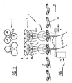
- a preferred embodiment according to the present invention (fig. 1 ) is provided with a conveyor (not shown) on which fruit carriers 3 (cups) are arranged. These fruit carriers have a centre-to-centre spacing of 100 to 200 mm. Sheets 5 are preferably mounted on the rear side of the cups. In the fruit carriers are situated fruits F on which measurements are done. Illuminating elements 7 are arranged for this purpose above the array of fruit carriers. These illuminating elements 7 comprise mirrors 8, lamps 9 and lens systems 10 which are ordered such that the light of the lamps is reflected by the mirrors to the lenses mounted under the lamps. Situated below the conveyor are two light receivers 11 which transport received light via glass fibre cables 12 to light measuring means (not shown).
- the cups 3 are transported in the direction of arrow A by the conveyor.
- Fruits F are situated in the cups. These fruits are illuminated from above by means of light L from lamps 9.
- This light has a wide wavelength range of preferably 300 to 2500 nanometres.
- the lamps each produce for instance 250 W and the light is focussed on the fruits by means of the lenses. Some of the light will be absorbed by the fruit, while some of the light will be able to penetrate through the fruit.
- the light passing through the fruit is transmitted through a hole situated in the centre of the cup, and part of it will be collected by the light receivers 11. In order to obtain a good measurement, it is recommended that the light receivers are able to collect light for the measurement for a determined period of time of for instance 100 milliseconds.
- the light receivers are transported forward at the same speed as a fruit carrier by linear motor 15 during illumination of the fruit, so that the light receivers are situated under the advancing cup and fruit during a measuring period. After this period the light receivers are moved back very rapidly so as to perform a similar measurement on two following fruits.
- An alternative method for reciprocating movement of the light receivers is by means of a crankshaft and drive shaft construction, which has the advantage that the rotation direction of the drive motor does not have to be reversed for reciprocating movement of the light receivers.
- the angular acceleration can further be precisely controlled in this case.
- a further advantage is that, at fruit transport speeds in the conveyors of up to seven fruits per second, it is possible to suffice with one light receiver, which results in a saving on these costly components and in a simple construction.
- the cups are provided with a sheet 5 over which the fruit can be carefully offloaded at a later stage and over which the fruit can roll out of the cup.
- this sheet is provided at a suitable location 6 with a hole which is situated during use under the hole of the following cup. It is hereby possible that the sheet of a preceding cup transmits the light of a cup on which measurement must be made.
- the light receivers are situated under the cups. Arranged round the light receivers is a light-excluding housing with a small hole on the top for passage of light. The object of this housing is that the least possible spurious light, i.e. light not irradiated through the product, will form part of the light sample.
- the cup is also manufactured from a dark material through which light cannot radiate, or only with difficulty.
- the hole on the underside of the cup can also be provided with an annular body of round, soft material which can also serve as light seal.
- Another object of such a ring is to form a soft bed for the products.
- the illuminating means can be embodied as,halogen lamps. Three lamps of 250 W can for instance be used per fruit carrier for illuminating.
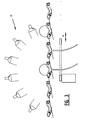
- Figure 2 shows a top view of the illuminating means 7 of figure 1 .
- the three fittings 16 present per fruit for illuminating have a focussing area 15 on which the light is focussed. This manner of illumination allows a high light intensity per fruit for illuminating.
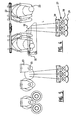
- Figure 3 shows a device similar to figure 1 .
- the light measuring means 17 here take a different form, however.
- six lamps are positioned in an arc.
- Such an illuminating arc enables various measurement configurations, two of which will now be discussed.
- a first measurement configuration is that all lamps shine with the same intensity and thus illuminate the fruit equally intensely from all sides.
- Such an illumination provides the light sample to be measured with information from the whole of the flesh of the fruit. If for instance a measurement of the sugar content of the whole flesh is important, such a measurement is recommended since information from the whole flesh will be included in the light sample. If however a measurement of a possible quantity of brown rot in the fruit is important, the two outer lamps can for instance be switched off, whereby the amount of information in the light sample will relate mainly to the middle of the fruit, whereby a relatively large amount of information about such brown rot will be included in the light sample.
- Such a measurement serves little purpose if for instance the fruit is provided with a large hard core or stone. In such cases a measurement and a light configuration directed at the outside of the fruit is of great importance.
- the fruit carrier is embodied as a pair of grippers 23, which are mounted suspended from opening and closing unit 22.
- This opening and closing unit 22 is fixed to a conveyor (not shown).
- illuminating unit 27 Below the conveyor with grippers is situated illuminating unit 27.
- the light L from the lamps 28 is radiated toward the fruit either via mirrors 29 or via lens system 30.
- the light is deflected by means of mirror 32 in order to enable irradiation of the fruit.
- Grippers 23 are provided with openings 33 for the passage of light L. If the grippers are carrying a fruit, the light will be radiated through a part of the fruit and collected by light receiver 34 situated in a housing 35.
- the light receiver 34 will co-displace for a short period with the fruit in order to allow a light measurement for a determined period of time.
- the illuminating unit 27 will also make a tilting movement so as to cause a focussed light beam to shine with the highest intensity for the same time period so that a maximum light output is available for the light reception.
- FIG. 6 shows another embodiment in which use is made of a diabolo 61.
- Each embodiment is provided with two light receivers 11 with two glass fibre cables for carrying the light samples to light measuring means (not shown).
- Fruits F are situated on the diabolos and are illuminated using the illuminating means 67.
- the light receiving means also co-displace for a short period of time with the fruits in order to obtain a high-quality light measurement. What is particularly important, however, is that the intensity over the measuring area is as uniform as possible.
- Figure 7 shows that diabolos 61, shown here in front view, consist of two halves between which there lies a space in which the light receiver 11 is movable. The diabolos advance together with the fruits in the direction of arrow B.
- figure 8 is shown a front view of a diabolo, wherein a lamp 68 is placed on the one side and a housing 69 for a light receiver is placed on the other side.
- Conveyor 101 is a diabolo conveyor which serves as singulating means for the fruit in a prior art fruit sorting device.
- the fruit supplied in the direction of movement of arrow C is supplied at the height of the broken lines D-D.
- the fruit will be transported along this line during all movements in this fruit sorting device.
- At the end of conveyor 101 the fruit will be picked up between the diabolos at the location of position P by the hands 111 of conveyor 104.
- Fruit F will be transported by these hands along line D to the cups of conveyor 102.
- the fruit will be set down carefully by the hands into cups 112 at position Q.
- an illuminating unit 120 Situated herein is a lamp and a lens system which emits light that illuminates the fruit F via mirror 121.
- the mirror can be a flat mirror which is slightly tiltable during the movement of the fruit, or the mirror can be a slightly convex mirror which spreads the light over the full path of the fruit during the measuring time period.
- An advantage of this embodiment of figure 9 is that the conveyor 102 used during the light measurement can be very short, for instance 0.5 to 2 metres. Only a few cups with openings are hereby required to do the light measurement and closed cups 113 can be used for a very long conveyor carrying the fruits to the final destination. If no use is made of a special short conveyor 102, a conveyor will be needed which has the length of conveyor 102 and 103 and which is provided over the whole length with cups with a hole. If it is important that the cups for the light measurement are very clean, a very long conveyor 102 would be very impractical in view of the cost and effort of cleaning. By keeping conveyor 102 very compact, the effort required to clean this conveyor can also be very limited.
- the conveyor 134 provided with hands or grippers for transporting the fruits takes a very long form.
- the transport takes place in this embodiment by means of the grippers.
- the light measurement takes place in similar manner as in figure 9 at the position of a short conveyor 132 which is provided with cups 142 as transport carrier.
- This embodiment is also provided with a singulating means 131 which singulates the fruits and feeds them to conveyor 134.
- the cup 3 as fruit carrier is provided with an opening on the underside thereof.
- the fruit lies in the cup on fruit-carrying part 151.
- the fruit stalks can protrude on the underside through the opening as shown in figure 11 .
- the edge takes the form of a droplet as seen in cross-section. Owing to this additional smooth thickening of the material of the opening of the cup, there is no possibility of stalks catching on the edge.
- FIG 12 A detail of light receiver 11 is shown in figure 12 . Shown are an opening 154 for admitting light radiated through the fruit. It is disadvantageous for light measurements if the light measuring means can become fouled rapidly. Fouling could be possible because dirt particles D enter the opening 154. In order to prevent this an airflow g is guided along opening 154.
- the light measuring means are provided with an air feed 156 and an air throughfeed 155.
- An airflow G is supplied through tube 156 to light measuring means 11 and guided through air throughfeed openings 155 in the direction of light aperture 154.
- Figure 13 shows a cross-section of a fruit F placed on a cup-like fruit carrier 3 under a lamp 7 which emits light L.
- a sheet 156 Fixed to the fruit carrier is a sheet 156 which is provided with a hole such that this hole is situated under the opening of the following cup of the conveyor (not shown) as described above.
- the sheet is trained along a sheet guide 150 such that the sheet remains clear of the light measuring means 11.
- the difference is known between the light intensity of the light incident upon the fruit and the light intensity of the light incident upon the light receiver.
- a calibration measurement is therefore carried out with some regularity, such as for instance every fifteen minutes, without fruit.
- the spectrum of the illuminating means is measured during such a calibration measurement. This effective spectrum of the illuminating means is hereby always up-to-date irrespective of the possible effects of ageing on these illuminating means.
- Figure 14 shows a cross-section as in figure 13 , wherein a reference filter 161 is shown under the sheet guide 150.
- This filter is used during a calibration measurement.
- the filter slides in front of the receiver a predetermined material transmitting very little light, such as for instance opal glass.
- the light which passes therethrough is received by the light receiver.
- Such a calibration measurement is important because a light source or radiation source can age, whereby the produced intensity spectrum can change. Radiation sources or lighting sources may also be replaced by other sources, or ambient influences may change such that a calibration measurement becomes necessary. Possible ageing or change of the light receiver can also be neutralized by means of a calibration measurement.
- Figure 15A shows a cross-section of a light measuring device wherein a reflection measurement is performed.
- diabolos are used to transport the fruits.
- Cup-like fruit carriers or grippers could also be used in performing such a measurement.
- the fruits are illuminated by means of lamps 67.
- the light receiving means 11 moving reciprocally with the fruit enable a light measurement as in a number of embodiments, in this case by means of reflection, by co-displacing with the fruit for a time and thereby achieving a relatively long receiving time. In this case measurement takes place on a part of the fruit located somewhat on the outer side of the fruit.
- figure 15A The embodiment of figure 15A is shown in figure 15B in top view.
- a fruit F lies on a fruit carrier formed by diabolo 61.
- Arrow A also indicates that light receiver 11 is moved reciprocally along the conveyor, whereby it is possible to take measurements on each fruit for a period of time.
Landscapes
- Health & Medical Sciences (AREA)
- General Health & Medical Sciences (AREA)
- Toxicology (AREA)
- Sorting Of Articles (AREA)
- Investigating Or Analysing Materials By Optical Means (AREA)
- Transition And Organic Metals Composition Catalysts For Addition Polymerization (AREA)
- Control And Other Processes For Unpacking Of Materials (AREA)
- Combined Means For Separation Of Solids (AREA)
- Confectionery (AREA)
- Apparatuses For Bulk Treatment Of Fruits And Vegetables And Apparatuses For Preparing Feeds (AREA)
Claims (39)
- Vorrichtung (1) zum Klassifizieren von Produkten wie z.B. Früchten mit
einer Anzahl von Fruchtträgern (3, 23, 61) zum Tragen der Produkte (F) auf einem Transportweg eines Förderers mit Klasssifizierungsausgängen,
einem Strahlungsmittel (7) zum Bestrahlen der Produkte,
einem oder mehreren Strahlungsempfangselementen (11) zum
Empfangen einer Strahlungsprobe der von dem Strahlungsmittel ausgesendeten Strahlung, nachdem sie das Produkt bestrahlt hat, während des Transports der Produkte auf dem Förderer,
dadurch gekennzeichnet, dass
zumindest die Strahlungsempfangselemente beweglich angeordnet sind zum Mitbewegen mit dem Produktträger während des Empfangens der Strahlungsprobe. - Vorrichtung nach Anspruch 1, bei der die Klassifizierung bei einer Transportgeschwindigkeit im Bereich von 5 bis 14 Früchten pro Sekunde durchgeführt wird.
- Vorrichtung nach einem oder mehreren der vorigen Ansprüche, bei der die Strahlungsempfangselemente angeordnet sind für eine Hin- und Herbewegung zum Zweck des Mitbewegens mit dem Produktträger während des Empfangens der Strahlungsprobe und des Zurückbewegens zwischen dem Empfangen aufeinanderfolgender Proben.
- Vorrichtung nach einem oder mehreren der vorigen Ansprüche, bei der die Strahlungsempfangselemente antreibbar mit einem Linearmotor (15) verbunden sind.
- Vorrichtung nach einem oder mehreren der vorigen Ansprüche, bei der die Strahlungsempfangselemente antreibbar mit einem Drehmotor verbunden sind, der mittels eines Kurbelwellen-Antriebsstangen-Aufbaus mit ihnen verbunden ist.
- Vorrichtung nach Anspruch 1 oder 2, bei der eine Anzahl von Strahlungsempfangselementen auf einem Messförderer angebracht sind, der auf die Geschwindigkeit des Förderers einstellbar ist.
- Vorrichtung nach einem oder mehreren der vorigen Ansprüche, bei der das Beleuchtungsmittel im Wesentlichen oberhalb des Transportwegs der Produktträger angeordnet ist.
- Vorrichtung nach einem oder mehreren der vorigen Ansprüche, die weiter ein Strahlungsmessmittel enthält zum Ausführen von Messungen an der von den Strahlungsempfangselementen empfangenen Strahlungsprobe.
- Vorrichtung nach einem oder mehreren der vorigen Ansprüche, die weiter ein Analysemittel enthält zum Analysieren der Strahlungsprobe.
- Vorrichtung nach einem oder mehreren der vorigen Ansprüche, bei der die Strahlung einen Wellenlängenbereich von 300 bis 2500 Nanometer hat.
- Vorrichtung nach einem oder mehreren der vorigen Ansprüche, die weiter ein Strahlungsführungsmittel enthält zum Führen der von den Strahlungsempfangselementen empfangenen Strahlung zu dem Strahlungsmessmittel.
- Vorrichtung nach einem oder mehreren der vorigen Ansprüche, bei der das Beleuchtungsmittel im wesentlichen benachbart zu dem Transportweg der Produktträger angeordnet ist.
- Vorrichtung nach einem oder mehreren der vorigen Ansprüche, bei der der Produktträger an der Unterseite mit einer Öffnung versehen ist zum Durchlassen der Strahlung von dem Strahlungsmittel, die durch das Produkt hindurchstrahlt.
- Vorrichtung nach Anspruch 13, bei der der Produktträger um die Öffnung herum einen ringförmigen Körper aus weichem Material enthält zum Tragen von zumindest relativ kleinen Produkten.
- Vorrichtung nach Anspruch 13 oder 14, bei der ein Produkttrageabschnitt der Schale eine Oberflächenkrümmung zum Tragen der Produkte aufweist, so dass relativ kleine Produkte näher an der Kante der Öffnung getragen werden und dass relativ große Produkte weiter entfernt von der Kante der Öffnung getragen werden.
- Vorrichtung nach einem oder mehreren der Ansprüche 13-15, bei der die Schale an einer Seite eine Ausnehmung hat zum Aufnehmen und/oder Ablegen von Produkten unter Verwendung von Greifmitteln.
- Vorrichtung nach einem oder mehreren der Ansprüche 13-16, bei der die Schale ein Blech (5) aufweist, das mit einer Öffnung in einem solchen Abstand von den Produkten versehen ist, dass das Loch des Blechs im Betrieb der Schale unter der nachfolgenden Schale des Endlosförderbands angeordnet ist.
- Vorrichtung nach einem oder mehreren der Ansprüche 1-12, bei der der Produktträger Greifelemente (23) enthält, die von zwei Seiten an den Früchten angreifen.
- Vorrichtung nach Anspruch 18, bei der
zumindest eines der Greifelemente mit einer Öffnung (33) versehen ist zum Durchlassen des Lichts von dem Beleuchtungsmittel, das durch das Produkt hindurchstrahlt, und
zumindest eines der Greifelemente auf der anderen Seite des Produkts lichtdurchlässig ist. - Vorrichtung nach einem oder mehreren der Ansprüche 1-12, bei der der Produktträger zwei Diabolo-förmige Elemente (61) enthält.
- Vorrichtung nach Anspruch 20, die mit einem Diaboloförmigen Körper versehen ist, der zwei Halbdiabolos mit einer Öffnung zwischen ihnen enthält.
- Vorrichtung nach einem oder mehreren der Ansprüche 13-21, bei der die Strahlungsempfangselemente unter dem Produktträger angeordnet sind.
- Vorrichtung nach einem oder mehreren der Ansprüche 18-21, bei der die Strahlungsempfangselemente angrenzend an den Produktträger angeordnet sind.
- Vorrichtung nach einem oder mehreren der vorigen Ansprüche, die zwei oder mehr Empfangselemente enthält zum gleichzeitigen Empfangen von Lichtproben einer Mehrzahl von Produktträgern.
- Vorrichtung nach einem oder mehreren der vorigen Ansprüche, die Strahlungsregulierungselemente auf jeder Seite des Strahlungsstrahls des Strahlungsmittels zu den Produktträgern enthält zum Abblocken von Strahlung, die nicht zu dem Produktträger gerichtet ist.
- Vorrichtung nach Anspruch 25, bei der die Strahlungsregulierungselemente beweglich sind zum Verändern der Breite und/oder Position des übertragenen Strahlungsstrahls.
- Vorrichtung nach Anspruch 25 oder 26, bei der die Strahlungsregulierungselemente aus reflektierendem Material hergestellt sind zum Reflektieren der Strahlung.
- Vorrichtung nach einem oder mehreren der vorigen Ansprüche, bei der
der Produktträger für einen Förderer von oben gesehen eine sich nach unten verjüngende Kontur aufweist zum Halten eines Produkts in der Mitte,
wobei die Kontur drei oder mehr Linien oder Flächen zum Tragen des Produkts aufweist. - Vorrichtung nach Anspruch 28, bei der der Produktträger weiter in der Mitte der Kontur eine Öffnung aufweist.
- Vorrichtung nach Anspruch 28 oder 29, bei der
der Produktträger weiter ein Blech enthält, das mit einer Öffnung versehen ist,
wobei der Abstand zwischen der Öffnung und der Öffnung eines folgenden Produktträgers ungefähr gleich dem Teilungsabstand des Förderers ist. - Vorrichtung nach einem oder mehreren der Ansprüche 29 bis 30, bei der im Wesentlichen in der und um die Öffnung des Lochs herum ein ringförmiger Körper aus weichem oder nachgiebigem Material angeordnet ist zum Halten relativ kleiner Produkte.
- Vorrichtung nach einem oder mehreren der Ansprüche 28 bis 31, bei der im Wesentlichen in der und um die Öffnung des Lochs herum ein ringförmiger Körper aus lichtabsorbierendem Material angeordnet ist zum lichtdichten Abschließen des Zwischenraums zwischen dem Fruchtträger und der Frucht.
- Verfahren zur Aufnahme von Messungen an Früchten (F), bei dem die Frucht über einen Förderer einer Fruchtsortiervorrichtung zugeführt wird, wobei das Verfahren die folgenden Schritte enthält:Beleuchten einer oder mehrerer Früchte während des Transports mit einem oder mehreren Fruchtträgern (3),Empfangen einer Lichtprobe des Beleuchtungsmittels (7), die durch die Probe hindurchgestrahlt wird,Durchführen einer oder mehrerer Messungen an der Lichtprobe,Gruppieren der Frucht in eine Klasse und Freigeben der Frucht an einer mit Bezug auf diese Klasse vorbestimmten Freigabeposition der Fruchtsortiervorrichtung,wobei zumindest die Strahlungsempfangselemente beweglich angeordnet sind zum Mitbewegen mit dem Produktträger während des Empfangens der Strahlungsprobe.
- Verfahren nach Anspruch 33, das weiter einen oder mehrere Schritte des Interpretieren der Messungen durch ein Analysemittel enthält.
- Verfahren nach Anspruch 33 oder 34, bei dem die Früchte auf der Grundlage der Messungen oder ihrer Interpretationen in Klassen mit vorbestimmten Eigenschaften gruppiert werden.
- Verfahren nach einem oder mehreren der vorigen Ansprüche 33 bis 35, das weiter Schritte zum Durchführen einer Lichtmessung ohne Frucht zu vorbestimmten Zeiten enthält zum Zweck der Kalibrierung des Lichtmessmittels in Verbindung mit der Strahlungsquelle.
- Verfahren nach einem oder mehreren der Ansprüche 33 bis 36, bei dem die Früchte von oben beleuchtet werden und eine Lichtprobe von der Unterseite der Frucht genommen wird.
- Verfahren nach einem oder mehreren der Ansprüche 33 bis 37, bei dem die Sortiergeschwindigkeit in dem Bereich von 5 bis 14 pro Sekunde liegt.
- Verfahren nach einem oder mehreren der Ansprüche 33 bis 38, bei dem der Abstand zwischen zwei aufeinanderfolgenden Produktträgern in dem Bereich von 90 bis 200 mm liegt.
Applications Claiming Priority (3)
| Application Number | Priority Date | Filing Date | Title |
|---|---|---|---|
| NL1019600 | 2001-12-18 | ||
| NL1019600A NL1019600C2 (nl) | 2001-12-18 | 2001-12-18 | Inrichting voor het classificeren van producten. |
| PCT/NL2002/000847 WO2003051540A1 (en) | 2001-12-18 | 2002-12-18 | Device for classifying products |
Publications (2)
| Publication Number | Publication Date |
|---|---|
| EP1455960A1 EP1455960A1 (de) | 2004-09-15 |
| EP1455960B1 true EP1455960B1 (de) | 2008-02-20 |
Family
ID=19774406
Family Applications (1)
| Application Number | Title | Priority Date | Filing Date |
|---|---|---|---|
| EP02789024A Expired - Lifetime EP1455960B1 (de) | 2001-12-18 | 2002-12-18 | Vorrichtung zur produktklassifizierung |
Country Status (8)
| Country | Link |
|---|---|
| US (1) | US7622691B2 (de) |
| EP (1) | EP1455960B1 (de) |
| AT (1) | ATE386595T1 (de) |
| AU (1) | AU2002353665A1 (de) |
| DE (1) | DE60225179T2 (de) |
| ES (1) | ES2299617T3 (de) |
| NL (1) | NL1019600C2 (de) |
| WO (1) | WO2003051540A1 (de) |
Families Citing this family (8)
| Publication number | Priority date | Publication date | Assignee | Title |
|---|---|---|---|---|
| ES2257935A1 (es) * | 2004-06-18 | 2006-08-01 | Calibrafruta-Serralharia Mecanica, Lda. | Dispositivo para calibrar y pesar fruta. |
| JP5449997B2 (ja) * | 2009-11-09 | 2014-03-19 | 株式会社マルハニチロ水産 | 魚卵熟度判定装置及び魚卵熟度判定方法 |
| ES2468395B1 (es) * | 2012-11-16 | 2014-12-16 | Citrodiagnosis Selectiva S.L. | Máquina automática para la inspección, detección y separación de frutos en fresco en su valoración cualitativa relativa al podrido y defectos externos |
| US9227229B2 (en) | 2013-04-08 | 2016-01-05 | National Recovery Technologies, Llc | Method to improve detection of thin walled polyethylene terephthalate containers for recycling including those containing liquids |
| US9234838B2 (en) | 2013-04-08 | 2016-01-12 | National Recovery Technologies, Llc | Method to improve detection of thin walled polyethylene terephthalate containers for recycling including those containing liquids |
| NL2017071B1 (nl) | 2016-06-29 | 2018-01-05 | De Greef's Wagen- Carrosserie- En Machb B V | Meetinrichting voor het meten van producten en werkwijze daarvoor |
| DE102018107689A1 (de) * | 2018-03-29 | 2019-10-02 | Krones Ag | Verfahren und Vorrichtung zum Inspizieren von Behältnissen |
| US12276493B2 (en) * | 2021-07-23 | 2025-04-15 | Markem-Imaje Corporation | Method and apparatus for characterizing objects using a light-emitting array |
Family Cites Families (10)
| Publication number | Priority date | Publication date | Assignee | Title |
|---|---|---|---|---|
| FR1011349A (fr) * | 1949-01-21 | 1952-06-23 | Procédé et dispositif pour le triage des fruits et légumes | |
| US3930994A (en) * | 1973-10-03 | 1976-01-06 | Sunkist Growers, Inc. | Method and means for internal inspection and sorting of produce |
| US4035636A (en) * | 1976-04-20 | 1977-07-12 | Amf Incorporated | Apparatus for measuring the internal quality of produce |
| US4585126A (en) * | 1983-10-28 | 1986-04-29 | Sunkist Growers, Inc. | Method and apparatus for high speed processing of fruit or the like |
| FR2710564B1 (fr) * | 1993-10-01 | 1995-11-24 | Iname Int | Dispositif de reconnaissance et/ou de tri de fruits ou légumes, procédé et utilisation correspondants. |
| FR2726651B1 (fr) * | 1994-11-08 | 1997-01-03 | Bertin & Cie | Procede et dispositif de detection de corps etrangers dans des recipients transparents tels que des bouteilles |
| WO2000013809A1 (en) * | 1998-09-07 | 2000-03-16 | Hamish Alexander Nigel Kennedy | Quality sorting of produce |
| US20010032807A1 (en) * | 2000-02-28 | 2001-10-25 | Powell Harry C. | Fruit handling with color sorting |
| ES2214417T3 (es) * | 2000-05-29 | 2004-09-16 | Fps Food Processing Systems B.V. | Sistema de deteccion para aparatos clasificadores. |
| EP1340512A1 (de) * | 2002-02-28 | 2003-09-03 | Ion Beam Applications S.A. | Vorrichtung und Verfahren zur Bestrahlung von Produkten auf Paletten |
-
2001
- 2001-12-18 NL NL1019600A patent/NL1019600C2/nl not_active IP Right Cessation
-
2002
- 2002-12-18 AT AT02789024T patent/ATE386595T1/de active
- 2002-12-18 AU AU2002353665A patent/AU2002353665A1/en not_active Abandoned
- 2002-12-18 DE DE60225179T patent/DE60225179T2/de not_active Expired - Lifetime
- 2002-12-18 EP EP02789024A patent/EP1455960B1/de not_active Expired - Lifetime
- 2002-12-18 ES ES02789024T patent/ES2299617T3/es not_active Expired - Lifetime
- 2002-12-18 WO PCT/NL2002/000847 patent/WO2003051540A1/en not_active Ceased
- 2002-12-18 US US10/499,582 patent/US7622691B2/en not_active Expired - Lifetime
Also Published As
| Publication number | Publication date |
|---|---|
| ES2299617T3 (es) | 2008-06-01 |
| DE60225179T2 (de) | 2009-02-12 |
| DE60225179D1 (de) | 2008-04-03 |
| AU2002353665A1 (en) | 2003-06-30 |
| WO2003051540A1 (en) | 2003-06-26 |
| EP1455960A1 (de) | 2004-09-15 |
| ATE386595T1 (de) | 2008-03-15 |
| US20080169225A1 (en) | 2008-07-17 |
| US7622691B2 (en) | 2009-11-24 |
| NL1019600C2 (nl) | 2003-06-19 |
Similar Documents
| Publication | Publication Date | Title |
|---|---|---|
| JP7091388B2 (ja) | 物質を検出する方法および装置 | |
| EP1197742B1 (de) | Vorrichtung zum on-line prüfen der inneren qualität mittels mehreren seitlichen lampen | |
| CN1430723A (zh) | 用可见光/近红外光谱测量和相关水果特性的方法和装置 | |
| US7622691B2 (en) | Device for classifying products | |
| EP1746409A1 (de) | Internes on-line-qualitätsuntersuchungsverfahren und vorrichtung | |
| AU1982097A (en) | Optical inspection apparatus and method for articles | |
| EP1269153B1 (de) | Spektralbewertung von Obst | |
| JP2006267037A (ja) | 青果類の内部品質評価装置および内部品質評価方法 | |
| JPH11165135A (ja) | 農産物選別装置用の受皿及びこれを用いた農産物選別装置 | |
| JP2003021598A (ja) | 青果類の評価装置 | |
| KR200371649Y1 (ko) | 휴대형 프로브가 구비된 비파괴 당/산도 측정 장치 | |
| CN1010167B (zh) | 自动选蛋机 | |
| JP2004219376A (ja) | 果菜類の品質評価装置 | |
| CN118080392A (zh) | 烟叶品质检测设备、烟叶分选系统以及烟草生产系统 | |
| AU755109B2 (en) | Spectral assessment of fruit | |
| CN120490003A (zh) | 基于动态红外光源触发技术的单籽粒透射光谱检测装置 | |
| JP2004163401A (ja) | 検出器 | |
| EP1371425A1 (de) | Detektor |
Legal Events
| Date | Code | Title | Description |
|---|---|---|---|
| PUAI | Public reference made under article 153(3) epc to a published international application that has entered the european phase |
Free format text: ORIGINAL CODE: 0009012 |
|
| 17P | Request for examination filed |
Effective date: 20040607 |
|
| AK | Designated contracting states |
Kind code of ref document: A1 Designated state(s): AT BE BG CH CY CZ DE DK EE ES FI FR GB GR IE IT LI LU MC NL PT SE SI SK TR |
|
| AX | Request for extension of the european patent |
Extension state: AL LT LV MK RO |
|
| 17Q | First examination report despatched |
Effective date: 20070309 |
|
| GRAP | Despatch of communication of intention to grant a patent |
Free format text: ORIGINAL CODE: EPIDOSNIGR1 |
|
| GRAS | Grant fee paid |
Free format text: ORIGINAL CODE: EPIDOSNIGR3 |
|
| GRAA | (expected) grant |
Free format text: ORIGINAL CODE: 0009210 |
|
| AK | Designated contracting states |
Kind code of ref document: B1 Designated state(s): AT BE BG CH CY CZ DE DK EE ES FI FR GB GR IE IT LI LU MC NL PT SE SI SK TR |
|
| REG | Reference to a national code |
Ref country code: GB Ref legal event code: FG4D |
|
| REG | Reference to a national code |
Ref country code: CH Ref legal event code: EP Ref country code: CH Ref legal event code: NV Representative=s name: ARNOLD & SIEDSMA AG |
|
| REG | Reference to a national code |
Ref country code: IE Ref legal event code: FG4D |
|
| REF | Corresponds to: |
Ref document number: 60225179 Country of ref document: DE Date of ref document: 20080403 Kind code of ref document: P |
|
| REG | Reference to a national code |
Ref country code: ES Ref legal event code: FG2A Ref document number: 2299617 Country of ref document: ES Kind code of ref document: T3 |
|
| PG25 | Lapsed in a contracting state [announced via postgrant information from national office to epo] |
Ref country code: FI Free format text: LAPSE BECAUSE OF FAILURE TO SUBMIT A TRANSLATION OF THE DESCRIPTION OR TO PAY THE FEE WITHIN THE PRESCRIBED TIME-LIMIT Effective date: 20080220 |
|
| PG25 | Lapsed in a contracting state [announced via postgrant information from national office to epo] |
Ref country code: SI Free format text: LAPSE BECAUSE OF FAILURE TO SUBMIT A TRANSLATION OF THE DESCRIPTION OR TO PAY THE FEE WITHIN THE PRESCRIBED TIME-LIMIT Effective date: 20080220 |
|
| ET | Fr: translation filed | ||
| PG25 | Lapsed in a contracting state [announced via postgrant information from national office to epo] |
Ref country code: DK Free format text: LAPSE BECAUSE OF FAILURE TO SUBMIT A TRANSLATION OF THE DESCRIPTION OR TO PAY THE FEE WITHIN THE PRESCRIBED TIME-LIMIT Effective date: 20080220 Ref country code: SE Free format text: LAPSE BECAUSE OF FAILURE TO SUBMIT A TRANSLATION OF THE DESCRIPTION OR TO PAY THE FEE WITHIN THE PRESCRIBED TIME-LIMIT Effective date: 20080520 Ref country code: CZ Free format text: LAPSE BECAUSE OF FAILURE TO SUBMIT A TRANSLATION OF THE DESCRIPTION OR TO PAY THE FEE WITHIN THE PRESCRIBED TIME-LIMIT Effective date: 20080220 Ref country code: PT Free format text: LAPSE BECAUSE OF FAILURE TO SUBMIT A TRANSLATION OF THE DESCRIPTION OR TO PAY THE FEE WITHIN THE PRESCRIBED TIME-LIMIT Effective date: 20080721 Ref country code: SK Free format text: LAPSE BECAUSE OF FAILURE TO SUBMIT A TRANSLATION OF THE DESCRIPTION OR TO PAY THE FEE WITHIN THE PRESCRIBED TIME-LIMIT Effective date: 20080220 |
|
| PLBE | No opposition filed within time limit |
Free format text: ORIGINAL CODE: 0009261 |
|
| STAA | Information on the status of an ep patent application or granted ep patent |
Free format text: STATUS: NO OPPOSITION FILED WITHIN TIME LIMIT |
|
| 26N | No opposition filed |
Effective date: 20081121 |
|
| PG25 | Lapsed in a contracting state [announced via postgrant information from national office to epo] |
Ref country code: EE Free format text: LAPSE BECAUSE OF FAILURE TO SUBMIT A TRANSLATION OF THE DESCRIPTION OR TO PAY THE FEE WITHIN THE PRESCRIBED TIME-LIMIT Effective date: 20080220 Ref country code: BG Free format text: LAPSE BECAUSE OF FAILURE TO SUBMIT A TRANSLATION OF THE DESCRIPTION OR TO PAY THE FEE WITHIN THE PRESCRIBED TIME-LIMIT Effective date: 20080520 |
|
| PG25 | Lapsed in a contracting state [announced via postgrant information from national office to epo] |
Ref country code: MC Free format text: LAPSE BECAUSE OF NON-PAYMENT OF DUE FEES Effective date: 20081231 Ref country code: CY Free format text: LAPSE BECAUSE OF FAILURE TO SUBMIT A TRANSLATION OF THE DESCRIPTION OR TO PAY THE FEE WITHIN THE PRESCRIBED TIME-LIMIT Effective date: 20080220 |
|
| PG25 | Lapsed in a contracting state [announced via postgrant information from national office to epo] |
Ref country code: IE Free format text: LAPSE BECAUSE OF NON-PAYMENT OF DUE FEES Effective date: 20081218 |
|
| PG25 | Lapsed in a contracting state [announced via postgrant information from national office to epo] |
Ref country code: LU Free format text: LAPSE BECAUSE OF NON-PAYMENT OF DUE FEES Effective date: 20081218 |
|
| PG25 | Lapsed in a contracting state [announced via postgrant information from national office to epo] |
Ref country code: TR Free format text: LAPSE BECAUSE OF FAILURE TO SUBMIT A TRANSLATION OF THE DESCRIPTION OR TO PAY THE FEE WITHIN THE PRESCRIBED TIME-LIMIT Effective date: 20080220 |
|
| PG25 | Lapsed in a contracting state [announced via postgrant information from national office to epo] |
Ref country code: GR Free format text: LAPSE BECAUSE OF FAILURE TO SUBMIT A TRANSLATION OF THE DESCRIPTION OR TO PAY THE FEE WITHIN THE PRESCRIBED TIME-LIMIT Effective date: 20080521 |
|
| REG | Reference to a national code |
Ref country code: FR Ref legal event code: PLFP Year of fee payment: 14 |
|
| REG | Reference to a national code |
Ref country code: FR Ref legal event code: PLFP Year of fee payment: 15 |
|
| REG | Reference to a national code |
Ref country code: FR Ref legal event code: PLFP Year of fee payment: 16 |
|
| PGFP | Annual fee paid to national office [announced via postgrant information from national office to epo] |
Ref country code: FR Payment date: 20211227 Year of fee payment: 20 Ref country code: GB Payment date: 20211227 Year of fee payment: 20 Ref country code: DE Payment date: 20211227 Year of fee payment: 20 Ref country code: AT Payment date: 20211221 Year of fee payment: 20 |
|
| PGFP | Annual fee paid to national office [announced via postgrant information from national office to epo] |
Ref country code: NL Payment date: 20211226 Year of fee payment: 20 Ref country code: IT Payment date: 20211221 Year of fee payment: 20 Ref country code: BE Payment date: 20211227 Year of fee payment: 20 |
|
| PGFP | Annual fee paid to national office [announced via postgrant information from national office to epo] |
Ref country code: CH Payment date: 20220104 Year of fee payment: 20 |
|
| PGFP | Annual fee paid to national office [announced via postgrant information from national office to epo] |
Ref country code: ES Payment date: 20220103 Year of fee payment: 20 |
|
| REG | Reference to a national code |
Ref country code: DE Ref legal event code: R071 Ref document number: 60225179 Country of ref document: DE |
|
| REG | Reference to a national code |
Ref country code: NL Ref legal event code: MK Effective date: 20221217 |
|
| REG | Reference to a national code |
Ref country code: CH Ref legal event code: PL |
|
| REG | Reference to a national code |
Ref country code: GB Ref legal event code: PE20 Expiry date: 20221217 |
|
| REG | Reference to a national code |
Ref country code: BE Ref legal event code: MK Effective date: 20221218 |
|
| PG25 | Lapsed in a contracting state [announced via postgrant information from national office to epo] |
Ref country code: GB Free format text: LAPSE BECAUSE OF EXPIRATION OF PROTECTION Effective date: 20221217 |
|
| REG | Reference to a national code |
Ref country code: AT Ref legal event code: MK07 Ref document number: 386595 Country of ref document: AT Kind code of ref document: T Effective date: 20221218 |
|
| REG | Reference to a national code |
Ref country code: ES Ref legal event code: FD2A Effective date: 20230427 |
|
| PG25 | Lapsed in a contracting state [announced via postgrant information from national office to epo] |
Ref country code: ES Free format text: LAPSE BECAUSE OF EXPIRATION OF PROTECTION Effective date: 20221219 |