EP1456063B1 - Air-bag - Google Patents
Air-bag Download PDFInfo
- Publication number
- EP1456063B1 EP1456063B1 EP20020791132 EP02791132A EP1456063B1 EP 1456063 B1 EP1456063 B1 EP 1456063B1 EP 20020791132 EP20020791132 EP 20020791132 EP 02791132 A EP02791132 A EP 02791132A EP 1456063 B1 EP1456063 B1 EP 1456063B1
- Authority
- EP
- European Patent Office
- Prior art keywords
- supply duct
- air
- gas supply
- fabric
- bag
- Prior art date
- Legal status (The legal status is an assumption and is not a legal conclusion. Google has not performed a legal analysis and makes no representation as to the accuracy of the status listed.)
- Expired - Lifetime
Links
Images


Classifications
-
- B—PERFORMING OPERATIONS; TRANSPORTING
- B60—VEHICLES IN GENERAL
- B60R—VEHICLES, VEHICLE FITTINGS, OR VEHICLE PARTS, NOT OTHERWISE PROVIDED FOR
- B60R21/00—Arrangements or fittings on vehicles for protecting or preventing injuries to occupants or pedestrians in case of accidents or other traffic risks
- B60R21/02—Occupant safety arrangements or fittings, e.g. crash pads
- B60R21/16—Inflatable occupant restraints or confinements designed to inflate upon impact or impending impact, e.g. air bags
- B60R21/23—Inflatable members
- B60R21/231—Inflatable members characterised by their shape, construction or spatial configuration
- B60R21/2334—Expansion control features
- B60R21/2346—Soft diffusers
-
- B—PERFORMING OPERATIONS; TRANSPORTING
- B60—VEHICLES IN GENERAL
- B60R—VEHICLES, VEHICLE FITTINGS, OR VEHICLE PARTS, NOT OTHERWISE PROVIDED FOR
- B60R21/00—Arrangements or fittings on vehicles for protecting or preventing injuries to occupants or pedestrians in case of accidents or other traffic risks
- B60R21/02—Occupant safety arrangements or fittings, e.g. crash pads
- B60R21/16—Inflatable occupant restraints or confinements designed to inflate upon impact or impending impact, e.g. air bags
- B60R21/23—Inflatable members
- B60R21/231—Inflatable members characterised by their shape, construction or spatial configuration
- B60R21/232—Curtain-type airbags deploying mainly in a vertical direction from their top edge
-
- Y—GENERAL TAGGING OF NEW TECHNOLOGICAL DEVELOPMENTS; GENERAL TAGGING OF CROSS-SECTIONAL TECHNOLOGIES SPANNING OVER SEVERAL SECTIONS OF THE IPC; TECHNICAL SUBJECTS COVERED BY FORMER USPC CROSS-REFERENCE ART COLLECTIONS [XRACs] AND DIGESTS
- Y10—TECHNICAL SUBJECTS COVERED BY FORMER USPC
- Y10T—TECHNICAL SUBJECTS COVERED BY FORMER US CLASSIFICATION
- Y10T442/00—Fabric [woven, knitted, or nonwoven textile or cloth, etc.]
- Y10T442/30—Woven fabric [i.e., woven strand or strip material]
- Y10T442/3179—Woven fabric is characterized by a particular or differential weave other than fabric in which the strand denier or warp/weft pick count is specified
Definitions
- THE PRESENT INVENTION relates to an air-bag, and more particularly relates to an air-bag of the type in which an inner gas supply tube is provided within the air-bag, the gas supply tube being adapted to be connected to a gas generator, and having apertures formed in the wall thereof to direct gas into discrete inflatable regions or chambers formed within the air-bag.
- an air-bag which has a plurality of inflatable regions or chambers which are to be supplied with gas from a gas generator.
- an air-bag is a so-called “inflatable curtain” which is adapted to be mounted in the roof of the vehicle above the door openings of the vehicle, and is also adapted, when an accident occurs, to be deployed to lie adjacent the window openings formed in the door, thus forming a protective curtain located between the occupant of the vehicle and the side of the vehicle.
- inflatable curtains provide protection to the occupant of the vehicle in the event of a side impact or roll-over situation.
- US-6,199,898 B discloses a safety device of this type in which the inflatable curtain is formed of an inflatable element which is divided into a plurality of regions or chambers which are to be inflated.
- An internal fabric gas supply duct is provided. That gas supply duct is provided, along its length, with circular apertures formed in the wall of the duct through which gas can flow from the duct into those regions or chambers of the inflatable element which are to be inflated.
- the main fabric parts of the air-bag, and also the internal fabric gas supply duct are cut-out from a large sheet or roll of fabric in such a way that maximum use is made of the fabric so that there is minimum wastage.
- the internal fabric gas supply duct is simply formed by taking an elongate strip of fabric and folding it so that the opposed edges are brought together, those opposed edges being inserted between the adjacent edges of the layers of fabric which form the main part of the inflatable curtain. The super-imposed edges are stitched together.
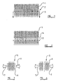
- Figure 1 which is provided for diagrammatic purposes, illustrates an element of fabric 1 having perpendicular warp and weft yarns.
- a line of stitching 2 is provided which is in alignment with one of the sets of yarns.
- Figure 1 illustrates the situation before tension is applied to the stitching 2, as indicated by the arrows 3.
- tension is applied to the stitching 2 in this way, a "yarn pull” or “combing” effect may be observed, with the tension applied to the stitching 2 serving to compress some of the yarns together, leaving a space 4 in which only one set of yarns is present. In an environment where fabric is expected to remain gas-tight, this is clearly undesirable.
- FIG 3 illustrates an element of fabric 5, where a very substantial tension is being applied to the warp yarns 6 as indicated schematically by the arrows 7. If the tension is sufficiently great, the warp yarns 6 will simply break, and the fabric will tear, as shown in Figure 4. This, again, is clearly undesirable.
- the present invention seeks to provide an improved air-bag.
- an air-bag the air-bag being formed from two super-imposed layers of fabric which define between them at least one inflatable region, there being a gas supply duct extending into the air-bag, the gas supply duct being provided with at least one aperture therein through which gas may flow into the said at least one inflatable region of the air-bag, the gas supply duct being of elongate form, and being formed of fabric having intersecting warp and weft yarns, the warp and weft yarns of said fabric being inclined at an angle of between 30° and 60° to the axis of the gas supply duct.
- the warp and weft yarns are inclined at an angle of between 40° and 50° to the axis of the gas supply duct.
- the warp and weft yarns are inclined at an angle of 45° to the axis of the gas supply duct.
- the spacing between the warp yarns is the same as the spacing between the weft yarns.
- the yarns make a symmetrical pattern, and the number of warp yarns in a regular area (such as 1cm 2 ) is equal to the umber of weft yarns.
- the gas supply duct is provided with circular apertures therein.
- the gas supply duct is provided with irregular shaped apertures therein.
- the gas supply duct is formed from a single elongate element of fabric which is folded so that the opposed edges thereof are super-imposed, with the super-imposed edges being secured together by stitching.
- the air-bag takes the form of an inflatable curtain, the air-bag defining a plurality of inflatable regions, wherein the gas supply duct is arranged to extend along one side edge of the air-bag, the gas supply duct being provided with apertures to supply gas to each of said inflatable regions.
- an air-bag in accordance with the present invention is illustrated in the form of a so-called inflatable curtain 10.
- the inflatable curtain 10 is formed from two super-imposed layers of fabric 11, 12, of similar outer shape.
- the layers of fabric 11,12 are interconnected by means of seams 13 which define inflatable regions 14, 15, 16.
- One of these inflatable regions 14 is sub-divided into inflatable chambers by means of seams 17 which interconnect the layers of fabric 11,12 in the region of said inflatable region 14.
- a protruding strap 18 is provided, the strap 18 being adapted to be connected to an anchoring point in a vehicle.
- a generally triangular extension 19 is provided which is also adapted to be connected to an anchoring point within the vehicle.
- the upper edge 20 of the inflatable curtain 10 is provided with a plurality of apertured mounting lugs 21 by means of which the inflatable curtain 10 may be mounted in position within a motor vehicle.
- the gas supply duct 22 is formed from a single element of fabric of elongate form which is folded about its axis so that the opposed side edges thereof are substantially super-imposed.
- the side edges of the fabric of the gas supply duct are inserted between the super-imposed upper side edges of the fabric layers 11 and 12 of the inflatable curtain 10, and the four super-imposed edges are interconnected by stitching 23 (see Figure 6).
- the lower-most part of the gas-supply duct 22 is provided with apertures 24 which are provided in those parts of the gas-supply duct which extend across the inflatable regions 14, 15, 16 of the inflatable curtain 10.
- the inflatable curtain gas 10 In use of the inflatable curtain gas 10, is supplied through the gas-supply duct 22 which becomes inflated, and gas passes through the apertures 24 formed in the gas supply duct 22 into the inflatable regions 14, 15, 16 to cause those regions of the inflatable curtain 10 to inflate.
- the inflatable curtain 10 has conventional features.
- the gas-supply duct 22 is formed of a fabric where the warp and weft yarns are not co-aligned with the axis of the gas-supply duct. Instead, the warp and weft yarns of the fabric forming the gas supply duct 22 each make an angle relative to the axis of the duct. The angle may be in the region of 30° - 60° or 40° - 50°, but the preferable angle is 45°. Of course, in such a preferred arrangement, each of the warp yarns and each of the weft yarns will make an angle of 45° relative to the axis of the gas-supply duct 22.
- the yarns make a symmetrical pattern as the number of warp yarns in reach regular area (such as 1 cm 2 ) of the fabric is equal to the number of weft yarns.
- regular area such as 1 cm 2
- the spacing between the warp yarns is the same as the spacing between the weft yarns.
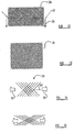
- Figure 8 is an enlarged view of part of the gas-supply duct 22 in accordance with the invention showing an aperture 24 formed therein, and showing the intersecting warp yarns and weft yarns, each making an angle relative to the axis of the gas-supply duct 22.
- the aperture 24 On inflation of the inflatable curtain 10, the aperture 24 will tend to change shape, and the aperture 24 may achieve a substantially square shape, as shown in Figure 9, on inflation of the inflatable curtain 10. It is found that the aperture 24, when in its square configuration, may have an area which is substantially greater than the area of the initial circular aperture 24. The increase in area may be in the region of 20% to 30% and may, in many cases be 27%.
- the maximum area of the square aperture, as shown in Figure 9 which is derived from the circular aperture shown in Figure 8, may be limited only by the warp yarns and the weft yarns surrounding the circular aperture which are not in any way cut to form the aperture.
- Figure 10 illustrates a further embodiment of the invention, in which an aperture 25 is provided in the gas-supply duct, the aperture 25 being of irregular shape. It is to be appreciated that with an aperture 25 of this shape, again, the aperture may effectively deform upon inflation to have a size and configuration (illustrated in Figure 11) which is bounded by the uncut warp and weft yarns which extend adjacent the aperture 25.
- aperture may be provided in the gas-supply duct, and indeed a square or “diamond"-shaped aperture, having its sides co-aligned with the warp and weft yarns may be provided if desired.
- the stitching 23 which secures the gas-flow duct to the fabric layers 11 and 12 of the inflatable curtain will extend at 45° to the warp yarns and weft yarns of the fabric forming the gas-flow duct 22.
- FIG 12 a portion of fabric 26 is shown, provided with a row of stitching 27.
- the stitching 27 extends at 45° to each of the warp yarns, and each of the weft yarns of the fabric 26.
- the stitching 27 is being shown (by arrows 28), subjected to a downward force, and thus Figure 12 effectively illustrates a situation corresponding to that illustrated in Figure 1, as discussed above.
- FIG 14 an element of fabric 29 is illustrated in which the warp yarns and weft yarns intersect, with the fabric being subjected to a force, as illustrated by the arrows 30, tending to apply tension to the fabric.
- the line of tension is not co-aligned with either the warp yarns or the weft yarns.
- the warp yarns and the weft yarns intersect the line of tension at approximately 45 0.
- the tube may initially have a configuration in which the yarns have a predetermined intersection angle. On inflation of the tube the intersection angle of the yarns may change to permit an increase in diameter of the tube, whilst tending to decrease the length of the tube.
Landscapes
- Engineering & Computer Science (AREA)
- Mechanical Engineering (AREA)
- Air Bags (AREA)
- Woven Fabrics (AREA)
- Medical Preparation Storing Or Oral Administration Devices (AREA)
- Packages (AREA)
Claims (8)
- Coussin de sécurité gonflable, le coussin de sécurité gonflable étant formé à partir de deux couches de tissu superposées qui définissent entre elles au moins une région gonflable, où un conduit d'alimentation de gaz s'étend dans le coussin de sécurité gonflable, le conduit d'alimentation de gaz étant prévu avec au moins une ouverture à l'intérieur de celui-ci, à travers lequel le gaz peut s'écouler dans ladite au moins une région gonflable du coussin de sécurité gonflable, le conduit d'alimentation de gaz ayant une forme allongée, et étant formé avec un tissu ayant des fils de chaîne et de trame qui se coupent, caractérisé en ce que les fils de chaîne et de trame dudit tissu sont inclinés selon un angle compris entre 30° et 60° par rapport à l'axe du conduit d'alimentation de gaz.
- Coussin de sécurité gonflable selon la revendication 1, dans lequel les fils de chaîne et de trame sont inclinés selon un angle compris entre 40° et 50° par rapport à l'axe du conduit d'alimentation de gaz.
- Coussin de sécurité gonflable selon la revendication 2, dans lequel les fils de chaîne et de trame sont inclinés selon un angle de 45° par rapport à l'axe du conduit d'alimentation de gaz.
- Coussin de sécurité gonflable selon l'une quelconque des revendications précédentes, dans lequel l'espacement entre les fils de chaîne est le même que l'espacement entre les fils de trame.
- Coussin de sécurité gonflable selon l'une quelconque des revendications précédentes, dans lequel le conduit d'alimentation de gaz est prévu avec des ouvertures circulaires à l'intérieur de celui-ci.
- Coussin de sécurité gonflable selon l'une quelconque des revendications 1 à 4, dans lequel le conduit d'alimentation de gaz est prévu avec des ouvertures de forme irrégulière à l'intérieur de celui-ci.
- Coussin de sécurité gonflable selon l'une quelconque des revendications précédentes, dans lequel le conduit d'alimentation de gaz est formé à partir d'un simple élément allongé de tissu qui est plié de sorte que ses bords opposés sont superposés, avec les bords superposés qui sont fixés ensemble par couture,
- Coussin de sécurité gonflable selon l'une quelconque des revendications précédentes, se présentant sous la forme d'un rideau gonflable, le coussin de sécurité gonflable définissant une pluralité de régions gonflables, dans lequel le conduit d'alimentation de gaz est agencé pour s'étendre le long d'un bord latéral du coussin de sécurité gonflable, le conduit d'alimentation de gaz étant prévu avec des ouvertures pour alimenter le gaz à chacune desdites régions gonflables.
Applications Claiming Priority (5)
| Application Number | Priority Date | Filing Date | Title |
|---|---|---|---|
| GB0130225A GB2383302A (en) | 2001-12-18 | 2001-12-18 | Airbag having a woven gas supply duct |
| GB0130225 | 2001-12-18 | ||
| GB0214686 | 2002-06-25 | ||
| GB0214686A GB2383306B (en) | 2001-12-18 | 2002-06-25 | Improvements in or relating to an air-bag |
| PCT/SE2002/002128 WO2003051679A1 (fr) | 2001-12-18 | 2002-11-22 | Air-bag |
Publications (2)
| Publication Number | Publication Date |
|---|---|
| EP1456063A1 EP1456063A1 (fr) | 2004-09-15 |
| EP1456063B1 true EP1456063B1 (fr) | 2007-08-08 |
Family
ID=26246881
Family Applications (1)
| Application Number | Title | Priority Date | Filing Date |
|---|---|---|---|
| EP20020791132 Expired - Lifetime EP1456063B1 (fr) | 2001-12-18 | 2002-11-22 | Air-bag |
Country Status (9)
| Country | Link |
|---|---|
| US (1) | US7458606B2 (fr) |
| EP (1) | EP1456063B1 (fr) |
| JP (1) | JP4100687B2 (fr) |
| CN (1) | CN1288011C (fr) |
| AT (1) | ATE369270T1 (fr) |
| AU (1) | AU2002366323A1 (fr) |
| DE (1) | DE60221704T2 (fr) |
| ES (1) | ES2291524T3 (fr) |
| WO (1) | WO2003051679A1 (fr) |
Families Citing this family (22)
| Publication number | Priority date | Publication date | Assignee | Title |
|---|---|---|---|---|
| GB2383302A (en) * | 2001-12-18 | 2003-06-25 | Autoliv Dev | Airbag having a woven gas supply duct |
| GB2389823A (en) | 2002-06-21 | 2003-12-24 | Autoliv Dev | An airbag having a gusset of excess fabric between the gas inlet throat and the inflatable region of the bag |
| GB2390576B (en) | 2002-07-12 | 2005-06-15 | Autoliv Dev | Improvements in or relating to an air-bag |
| GB2393692A (en) | 2002-10-01 | 2004-04-07 | Autoliv Dev | Air bag with reinforced apertures in gas duct |
| GB2399792A (en) | 2003-03-24 | 2004-09-29 | Autoliv Dev | An air-bag mounting arrangement |
| EP1698522B1 (fr) | 2003-12-08 | 2009-05-06 | Autoliv Development Ab | Dispositif airbag pour un vehicule |
| JP2008507455A (ja) | 2004-07-26 | 2008-03-13 | ニクスジェン・テクノロジーズ・エルエルシー | 膨張可能なエアバッグ |
| JP4604704B2 (ja) * | 2004-12-21 | 2011-01-05 | 豊田合成株式会社 | エアバッグ |
| DE102005001598A1 (de) * | 2005-01-12 | 2006-07-20 | Autoliv Development Ab | Airbag sowie Verfahren zum Herstellen eines Airbags |
| US20060208466A1 (en) * | 2005-03-18 | 2006-09-21 | Takata Restraint Systems, Inc. | Curtain airbag bottom fill |
| DE102005021371A1 (de) * | 2005-05-04 | 2006-11-23 | Autoliv Development Ab | Gassack |
| EP1728904B1 (fr) * | 2005-06-02 | 2007-08-08 | Polyamide High Performance GmbH | Tissu pour coussins gonflables |
| JP4424263B2 (ja) * | 2005-06-10 | 2010-03-03 | 株式会社豊田自動織機 | 繊維織物及び複合材 |
| US20110057425A1 (en) * | 2005-07-26 | 2011-03-10 | Fink Michael F | Side curtain airbag |
| US8240708B2 (en) * | 2005-07-26 | 2012-08-14 | Nxgen Technologies, Llc | Side curtain airbag with fabric diffuser |
| US20070102912A1 (en) * | 2005-11-08 | 2007-05-10 | Trw Vehicle Safety Systems Inc. | Vehicle occupant protection apparatus having a plastic fill tube |
| US20070228709A1 (en) * | 2006-03-30 | 2007-10-04 | Tk Holdings, Inc. | Airbag with gas diffuser |
| KR100996291B1 (ko) * | 2007-02-23 | 2010-11-23 | 코오롱인더스트리 주식회사 | 커튼형 에어백 및 그 제조방법 |
| JP2009040229A (ja) * | 2007-08-09 | 2009-02-26 | Takata Corp | 側突用エアバッグ装置 |
| US8573637B2 (en) | 2009-08-19 | 2013-11-05 | Nxgen Technologies, Llc | Side curtain airbag and method and apparatus for manufacturing a side curtain airbag |
| JP5653612B2 (ja) * | 2009-12-18 | 2015-01-14 | 住商エアバッグ・システムズ株式会社 | カーテンバッグ |
| DE102015108423A1 (de) * | 2015-05-28 | 2015-09-17 | Takata AG | Gassack für ein Airbagmodul |
Family Cites Families (27)
| Publication number | Priority date | Publication date | Assignee | Title |
|---|---|---|---|---|
| US1615517A (en) * | 1924-05-20 | 1927-01-25 | Mundorf Emil | Fulled woven fabric |
| US4238530A (en) * | 1979-07-24 | 1980-12-09 | Dayco Corporation | Method for producing stress-relieved fabric |
| US4325999A (en) * | 1979-11-23 | 1982-04-20 | Hitco | Bias fabric |
| JP3036215B2 (ja) * | 1992-03-18 | 2000-04-24 | タカタ株式会社 | エアバッグ |
| KR100252556B1 (ko) * | 1992-08-19 | 2000-04-15 | 이타가키 히로시 | 파열강도가높은에어백 |
| US5378019A (en) * | 1993-03-11 | 1995-01-03 | Morton International, Inc. | Controlled deployment driver's side air bag |
| JP3713810B2 (ja) * | 1996-05-17 | 2005-11-09 | 豊田合成株式会社 | 車両用エアバッグ |
| DE19727832A1 (de) * | 1997-06-23 | 1998-12-24 | Petri Ag | Flammschutzvorrichtung für Gassäcke von Airbagmodulen |
| EP1033292B1 (fr) * | 1997-11-28 | 2009-03-25 | Asahi Kasei Fibers Corporation | Coussin pneumatique de securite leger |
| US6073961A (en) * | 1998-02-20 | 2000-06-13 | Breed Automotive Technology, Inc. | Inflatable side airbag curtain module |
| DE29814990U1 (de) * | 1998-08-20 | 1998-12-17 | Trw Repa Gmbh | Gassack |
| US6530595B2 (en) * | 1998-08-20 | 2003-03-11 | Takata Corporation | Protective cushion for vehicle occupant's head |
| JP3876560B2 (ja) * | 1998-08-20 | 2007-01-31 | タカタ株式会社 | 自動車乗員頭部の保護バッグ |
| US6554314B1 (en) * | 1999-02-03 | 2003-04-29 | Takata Corporation | Protective cushion for vehicle occupant's head |
| JP4114303B2 (ja) * | 1999-07-15 | 2008-07-09 | タカタ株式会社 | エアバッグ、エアバッグ装置及びステアリング |
| JP2001097170A (ja) * | 1999-09-30 | 2001-04-10 | Nippon Plast Co Ltd | 側部用エアバッグ |
| US6883557B1 (en) * | 2001-03-30 | 2005-04-26 | Berger Seiba-Technotex Verwaltungs Gmbh Co. | Method for weaving an airbag |
| US6715791B2 (en) * | 2001-04-06 | 2004-04-06 | Milliken & Company | Air bag tether system comprising multiple segments cut in alignment with fabric warp of fill |
| US6755436B2 (en) * | 2001-06-26 | 2004-06-29 | Autoliv Asp, Inc. | Apparatus and method for airbag inflation gas distribution |
| GB2383302A (en) | 2001-12-18 | 2003-06-25 | Autoliv Dev | Airbag having a woven gas supply duct |
| EP1364839A3 (fr) * | 2002-05-24 | 2004-02-25 | Breed Automotive Technology, Inc. | Coussin gonflable de type rideau amélioré |
| KR100458188B1 (ko) * | 2002-06-17 | 2004-11-20 | 현대모비스 주식회사 | 자동차의 커튼 에어백. |
| GB2393692A (en) * | 2002-10-01 | 2004-04-07 | Autoliv Dev | Air bag with reinforced apertures in gas duct |
| US6945556B2 (en) * | 2002-11-29 | 2005-09-20 | Takata Restraint Systems, Inc. | Airbag fabric diffuser |
| US6978808B2 (en) * | 2003-07-17 | 2005-12-27 | Milliken & Company | Bias-woven side curtain airbag |
| US7354063B2 (en) * | 2004-03-09 | 2008-04-08 | Milliken & Company | Airbag structure |
| US7681917B2 (en) * | 2005-06-24 | 2010-03-23 | Zodiac Automotive Us Inc. | Sealing and reinforcing strips principally for airbag assembly joints |
-
2002
- 2002-11-22 DE DE2002621704 patent/DE60221704T2/de not_active Expired - Lifetime
- 2002-11-22 CN CNB02825287XA patent/CN1288011C/zh not_active Expired - Fee Related
- 2002-11-22 AT AT02791132T patent/ATE369270T1/de not_active IP Right Cessation
- 2002-11-22 WO PCT/SE2002/002128 patent/WO2003051679A1/fr not_active Ceased
- 2002-11-22 JP JP2003552581A patent/JP4100687B2/ja not_active Expired - Fee Related
- 2002-11-22 ES ES02791132T patent/ES2291524T3/es not_active Expired - Lifetime
- 2002-11-22 US US10/499,372 patent/US7458606B2/en not_active Expired - Lifetime
- 2002-11-22 AU AU2002366323A patent/AU2002366323A1/en not_active Abandoned
- 2002-11-22 EP EP20020791132 patent/EP1456063B1/fr not_active Expired - Lifetime
Also Published As
| Publication number | Publication date |
|---|---|
| US20050006881A1 (en) | 2005-01-13 |
| WO2003051679A1 (fr) | 2003-06-26 |
| CN1604861A (zh) | 2005-04-06 |
| EP1456063A1 (fr) | 2004-09-15 |
| ATE369270T1 (de) | 2007-08-15 |
| ES2291524T3 (es) | 2008-03-01 |
| JP2005511405A (ja) | 2005-04-28 |
| DE60221704D1 (en) | 2007-09-20 |
| DE60221704T2 (de) | 2008-04-30 |
| JP4100687B2 (ja) | 2008-06-11 |
| AU2002366323A1 (en) | 2003-06-30 |
| US7458606B2 (en) | 2008-12-02 |
| CN1288011C (zh) | 2006-12-06 |
Similar Documents
| Publication | Publication Date | Title |
|---|---|---|
| US7458606B2 (en) | Air-bag | |
| EP2086797B1 (fr) | Couture de déchirure de recouvrement de coussin de sécurité gonflable | |
| GB2383306A (en) | Airbag with a fabric gas supply duct | |
| US6626456B2 (en) | Apparatus and method for inflatable curtain wrap | |
| JP6513882B2 (ja) | 内部テザーを含むエアバッグ及びそれらを形成する方法 | |
| US7077426B2 (en) | Air-bag arrangement | |
| EP2407353A1 (fr) | Dispositif de sécurité de véhicule à moteur | |
| US6796577B2 (en) | Air-bag arrangement | |
| EP2174843B1 (fr) | Airbag | |
| GB2393692A (en) | Air bag with reinforced apertures in gas duct | |
| EP1536989B1 (fr) | Airbag | |
| US20030201630A1 (en) | Integral airbag exhaust vent | |
| JP2018176863A (ja) | カーテンエアバッグ装置 | |
| JP3769768B2 (ja) | エアバッグの圧力調整機構 | |
| JP7401686B2 (ja) | カーテンエアバッグ装置 | |
| JP7603637B2 (ja) | エアバッグ装置 | |
| WO2004085210A1 (fr) | Airbag |
Legal Events
| Date | Code | Title | Description |
|---|---|---|---|
| PUAI | Public reference made under article 153(3) epc to a published international application that has entered the european phase |
Free format text: ORIGINAL CODE: 0009012 |
|
| 17P | Request for examination filed |
Effective date: 20040421 |
|
| AK | Designated contracting states |
Kind code of ref document: A1 Designated state(s): AT BE BG CH CY CZ DE DK EE ES FI FR GB GR IE IT LI LU MC NL PT SE SK TR |
|
| AX | Request for extension of the european patent |
Extension state: AL LT LV MK RO SI |
|
| GRAP | Despatch of communication of intention to grant a patent |
Free format text: ORIGINAL CODE: EPIDOSNIGR1 |
|
| GRAS | Grant fee paid |
Free format text: ORIGINAL CODE: EPIDOSNIGR3 |
|
| GRAA | (expected) grant |
Free format text: ORIGINAL CODE: 0009210 |
|
| AK | Designated contracting states |
Kind code of ref document: B1 Designated state(s): AT BE BG CH CY CZ DE DK EE ES FI FR GR IE IT LI LU MC NL PT SE SK TR |
|
| RBV | Designated contracting states (corrected) |
Designated state(s): AT BE BG CH CY CZ DE DK EE ES FI FR GR IE IT LI LU MC NL PT SE SK TR |
|
| REG | Reference to a national code |
Ref country code: CH Ref legal event code: EP |
|
| REG | Reference to a national code |
Ref country code: IE Ref legal event code: FG4D |
|
| REF | Corresponds to: |
Ref document number: 60221704 Country of ref document: DE Date of ref document: 20070920 Kind code of ref document: P |
|
| ET | Fr: translation filed | ||
| PG25 | Lapsed in a contracting state [announced via postgrant information from national office to epo] |
Ref country code: BG Free format text: LAPSE BECAUSE OF FAILURE TO SUBMIT A TRANSLATION OF THE DESCRIPTION OR TO PAY THE FEE WITHIN THE PRESCRIBED TIME-LIMIT Effective date: 20071108 Ref country code: NL Free format text: LAPSE BECAUSE OF FAILURE TO SUBMIT A TRANSLATION OF THE DESCRIPTION OR TO PAY THE FEE WITHIN THE PRESCRIBED TIME-LIMIT Effective date: 20070808 Ref country code: FI Free format text: LAPSE BECAUSE OF FAILURE TO SUBMIT A TRANSLATION OF THE DESCRIPTION OR TO PAY THE FEE WITHIN THE PRESCRIBED TIME-LIMIT Effective date: 20070808 |
|
| NLV1 | Nl: lapsed or annulled due to failure to fulfill the requirements of art. 29p and 29m of the patents act | ||
| REG | Reference to a national code |
Ref country code: CH Ref legal event code: PL |
|
| PG25 | Lapsed in a contracting state [announced via postgrant information from national office to epo] |
Ref country code: CH Free format text: LAPSE BECAUSE OF FAILURE TO SUBMIT A TRANSLATION OF THE DESCRIPTION OR TO PAY THE FEE WITHIN THE PRESCRIBED TIME-LIMIT Effective date: 20070808 Ref country code: LI Free format text: LAPSE BECAUSE OF FAILURE TO SUBMIT A TRANSLATION OF THE DESCRIPTION OR TO PAY THE FEE WITHIN THE PRESCRIBED TIME-LIMIT Effective date: 20070808 Ref country code: AT Free format text: LAPSE BECAUSE OF FAILURE TO SUBMIT A TRANSLATION OF THE DESCRIPTION OR TO PAY THE FEE WITHIN THE PRESCRIBED TIME-LIMIT Effective date: 20070808 |
|
| REG | Reference to a national code |
Ref country code: ES Ref legal event code: FG2A Ref document number: 2291524 Country of ref document: ES Kind code of ref document: T3 |
|
| PG25 | Lapsed in a contracting state [announced via postgrant information from national office to epo] |
Ref country code: BE Free format text: LAPSE BECAUSE OF FAILURE TO SUBMIT A TRANSLATION OF THE DESCRIPTION OR TO PAY THE FEE WITHIN THE PRESCRIBED TIME-LIMIT Effective date: 20070808 |
|
| PG25 | Lapsed in a contracting state [announced via postgrant information from national office to epo] |
Ref country code: GR Free format text: LAPSE BECAUSE OF FAILURE TO SUBMIT A TRANSLATION OF THE DESCRIPTION OR TO PAY THE FEE WITHIN THE PRESCRIBED TIME-LIMIT Effective date: 20071109 Ref country code: DK Free format text: LAPSE BECAUSE OF FAILURE TO SUBMIT A TRANSLATION OF THE DESCRIPTION OR TO PAY THE FEE WITHIN THE PRESCRIBED TIME-LIMIT Effective date: 20070808 |
|
| PG25 | Lapsed in a contracting state [announced via postgrant information from national office to epo] |
Ref country code: SK Free format text: LAPSE BECAUSE OF FAILURE TO SUBMIT A TRANSLATION OF THE DESCRIPTION OR TO PAY THE FEE WITHIN THE PRESCRIBED TIME-LIMIT Effective date: 20070808 Ref country code: PT Free format text: LAPSE BECAUSE OF FAILURE TO SUBMIT A TRANSLATION OF THE DESCRIPTION OR TO PAY THE FEE WITHIN THE PRESCRIBED TIME-LIMIT Effective date: 20080108 Ref country code: CZ Free format text: LAPSE BECAUSE OF FAILURE TO SUBMIT A TRANSLATION OF THE DESCRIPTION OR TO PAY THE FEE WITHIN THE PRESCRIBED TIME-LIMIT Effective date: 20070808 |
|
| PLBE | No opposition filed within time limit |
Free format text: ORIGINAL CODE: 0009261 |
|
| STAA | Information on the status of an ep patent application or granted ep patent |
Free format text: STATUS: NO OPPOSITION FILED WITHIN TIME LIMIT |
|
| PG25 | Lapsed in a contracting state [announced via postgrant information from national office to epo] |
Ref country code: MC Free format text: LAPSE BECAUSE OF NON-PAYMENT OF DUE FEES Effective date: 20071130 Ref country code: SE Free format text: LAPSE BECAUSE OF FAILURE TO SUBMIT A TRANSLATION OF THE DESCRIPTION OR TO PAY THE FEE WITHIN THE PRESCRIBED TIME-LIMIT Effective date: 20071108 |
|
| 26N | No opposition filed |
Effective date: 20080509 |
|
| PG25 | Lapsed in a contracting state [announced via postgrant information from national office to epo] |
Ref country code: IE Free format text: LAPSE BECAUSE OF NON-PAYMENT OF DUE FEES Effective date: 20071122 |
|
| PG25 | Lapsed in a contracting state [announced via postgrant information from national office to epo] |
Ref country code: EE Free format text: LAPSE BECAUSE OF FAILURE TO SUBMIT A TRANSLATION OF THE DESCRIPTION OR TO PAY THE FEE WITHIN THE PRESCRIBED TIME-LIMIT Effective date: 20070808 |
|
| PGFP | Annual fee paid to national office [announced via postgrant information from national office to epo] |
Ref country code: ES Payment date: 20081117 Year of fee payment: 7 |
|
| PG25 | Lapsed in a contracting state [announced via postgrant information from national office to epo] |
Ref country code: CY Free format text: LAPSE BECAUSE OF FAILURE TO SUBMIT A TRANSLATION OF THE DESCRIPTION OR TO PAY THE FEE WITHIN THE PRESCRIBED TIME-LIMIT Effective date: 20070808 |
|
| PG25 | Lapsed in a contracting state [announced via postgrant information from national office to epo] |
Ref country code: LU Free format text: LAPSE BECAUSE OF NON-PAYMENT OF DUE FEES Effective date: 20071122 |
|
| PG25 | Lapsed in a contracting state [announced via postgrant information from national office to epo] |
Ref country code: TR Free format text: LAPSE BECAUSE OF FAILURE TO SUBMIT A TRANSLATION OF THE DESCRIPTION OR TO PAY THE FEE WITHIN THE PRESCRIBED TIME-LIMIT Effective date: 20070808 |
|
| REG | Reference to a national code |
Ref country code: ES Ref legal event code: FD2A Effective date: 20110329 |
|
| PG25 | Lapsed in a contracting state [announced via postgrant information from national office to epo] |
Ref country code: IT Free format text: LAPSE BECAUSE OF NON-PAYMENT OF DUE FEES Effective date: 20091122 |
|
| PG25 | Lapsed in a contracting state [announced via postgrant information from national office to epo] |
Ref country code: ES Free format text: LAPSE BECAUSE OF NON-PAYMENT OF DUE FEES Effective date: 20110316 |
|
| PGFP | Annual fee paid to national office [announced via postgrant information from national office to epo] |
Ref country code: IT Payment date: 20101119 Year of fee payment: 9 |
|
| PGRI | Patent reinstated in contracting state [announced from national office to epo] |
Ref country code: IT Effective date: 20110616 |
|
| PG25 | Lapsed in a contracting state [announced via postgrant information from national office to epo] |
Ref country code: ES Free format text: LAPSE BECAUSE OF NON-PAYMENT OF DUE FEES Effective date: 20091123 |
|
| PG25 | Lapsed in a contracting state [announced via postgrant information from national office to epo] |
Ref country code: IT Free format text: LAPSE BECAUSE OF NON-PAYMENT OF DUE FEES Effective date: 20121122 |
|
| REG | Reference to a national code |
Ref country code: FR Ref legal event code: PLFP Year of fee payment: 14 |
|
| REG | Reference to a national code |
Ref country code: FR Ref legal event code: PLFP Year of fee payment: 15 |
|
| REG | Reference to a national code |
Ref country code: FR Ref legal event code: PLFP Year of fee payment: 16 |
|
| PGFP | Annual fee paid to national office [announced via postgrant information from national office to epo] |
Ref country code: FR Payment date: 20191128 Year of fee payment: 18 |
|
| PGFP | Annual fee paid to national office [announced via postgrant information from national office to epo] |
Ref country code: DE Payment date: 20201125 Year of fee payment: 19 |
|
| PG25 | Lapsed in a contracting state [announced via postgrant information from national office to epo] |
Ref country code: FR Free format text: LAPSE BECAUSE OF NON-PAYMENT OF DUE FEES Effective date: 20201130 |
|
| REG | Reference to a national code |
Ref country code: DE Ref legal event code: R119 Ref document number: 60221704 Country of ref document: DE |
|
| PG25 | Lapsed in a contracting state [announced via postgrant information from national office to epo] |
Ref country code: DE Free format text: LAPSE BECAUSE OF NON-PAYMENT OF DUE FEES Effective date: 20220601 |