EP1456516B1 - Abschraubsicherungsvorrichtung für behälter - Google Patents
Abschraubsicherungsvorrichtung für behälter Download PDFInfo
- Publication number
- EP1456516B1 EP1456516B1 EP02796617A EP02796617A EP1456516B1 EP 1456516 B1 EP1456516 B1 EP 1456516B1 EP 02796617 A EP02796617 A EP 02796617A EP 02796617 A EP02796617 A EP 02796617A EP 1456516 B1 EP1456516 B1 EP 1456516B1
- Authority
- EP
- European Patent Office
- Prior art keywords
- security device
- container
- recited
- drive
- unscrewing
- Prior art date
- Legal status (The legal status is an assumption and is not a legal conclusion. Google has not performed a legal analysis and makes no representation as to the accuracy of the status listed.)
- Expired - Lifetime
Links
- 239000002775 capsule Substances 0.000 claims description 7
- 239000000463 material Substances 0.000 claims description 3
- 230000002265 prevention Effects 0.000 claims 2
- 238000007789 sealing Methods 0.000 abstract description 4
- 230000006835 compression Effects 0.000 description 10
- 238000007906 compression Methods 0.000 description 10
- 239000012528 membrane Substances 0.000 description 6
- 230000004044 response Effects 0.000 description 3
- 241000287116 Paridae Species 0.000 description 1
- 230000000903 blocking effect Effects 0.000 description 1
- 239000000110 cooling liquid Substances 0.000 description 1
- 230000002093 peripheral effect Effects 0.000 description 1
- 230000008719 thickening Effects 0.000 description 1
Images


Classifications
-
- F—MECHANICAL ENGINEERING; LIGHTING; HEATING; WEAPONS; BLASTING
- F01—MACHINES OR ENGINES IN GENERAL; ENGINE PLANTS IN GENERAL; STEAM ENGINES
- F01P—COOLING OF MACHINES OR ENGINES IN GENERAL; COOLING OF INTERNAL-COMBUSTION ENGINES
- F01P11/00—Component parts, details, or accessories not provided for in, or of interest apart from, groups F01P1/00 - F01P9/00
- F01P11/02—Liquid-coolant filling, overflow, venting, or draining devices
- F01P11/0204—Filling
- F01P11/0209—Closure caps
- F01P11/0247—Safety; Locking against opening
-
- F—MECHANICAL ENGINEERING; LIGHTING; HEATING; WEAPONS; BLASTING
- F01—MACHINES OR ENGINES IN GENERAL; ENGINE PLANTS IN GENERAL; STEAM ENGINES
- F01P—COOLING OF MACHINES OR ENGINES IN GENERAL; COOLING OF INTERNAL-COMBUSTION ENGINES
- F01P11/00—Component parts, details, or accessories not provided for in, or of interest apart from, groups F01P1/00 - F01P9/00
- F01P11/02—Liquid-coolant filling, overflow, venting, or draining devices
- F01P11/0204—Filling
- F01P11/0209—Closure caps
- F01P11/0238—Closure caps with overpressure valves or vent valves
-
- F—MECHANICAL ENGINEERING; LIGHTING; HEATING; WEAPONS; BLASTING
- F01—MACHINES OR ENGINES IN GENERAL; ENGINE PLANTS IN GENERAL; STEAM ENGINES
- F01P—COOLING OF MACHINES OR ENGINES IN GENERAL; COOLING OF INTERNAL-COMBUSTION ENGINES
- F01P11/00—Component parts, details, or accessories not provided for in, or of interest apart from, groups F01P1/00 - F01P9/00
- F01P11/02—Liquid-coolant filling, overflow, venting, or draining devices
- F01P11/029—Expansion reservoirs
-
- F—MECHANICAL ENGINEERING; LIGHTING; HEATING; WEAPONS; BLASTING
- F01—MACHINES OR ENGINES IN GENERAL; ENGINE PLANTS IN GENERAL; STEAM ENGINES
- F01P—COOLING OF MACHINES OR ENGINES IN GENERAL; COOLING OF INTERNAL-COMBUSTION ENGINES
- F01P11/00—Component parts, details, or accessories not provided for in, or of interest apart from, groups F01P1/00 - F01P9/00
- F01P11/02—Liquid-coolant filling, overflow, venting, or draining devices
- F01P11/0204—Filling
- F01P11/0209—Closure caps
- F01P11/0247—Safety; Locking against opening
- F01P2011/0261—Safety; Locking against opening activated by temperature
-
- F—MECHANICAL ENGINEERING; LIGHTING; HEATING; WEAPONS; BLASTING
- F01—MACHINES OR ENGINES IN GENERAL; ENGINE PLANTS IN GENERAL; STEAM ENGINES
- F01P—COOLING OF MACHINES OR ENGINES IN GENERAL; COOLING OF INTERNAL-COMBUSTION ENGINES
- F01P11/00—Component parts, details, or accessories not provided for in, or of interest apart from, groups F01P1/00 - F01P9/00
- F01P11/02—Liquid-coolant filling, overflow, venting, or draining devices
- F01P11/0204—Filling
- F01P11/0209—Closure caps
- F01P11/0247—Safety; Locking against opening
- F01P2011/0266—Safety; Locking against opening activated by pressure
-
- F—MECHANICAL ENGINEERING; LIGHTING; HEATING; WEAPONS; BLASTING
- F01—MACHINES OR ENGINES IN GENERAL; ENGINE PLANTS IN GENERAL; STEAM ENGINES
- F01P—COOLING OF MACHINES OR ENGINES IN GENERAL; COOLING OF INTERNAL-COMBUSTION ENGINES
- F01P2070/00—Details
- F01P2070/06—Using intake pressure as actuating fluid
-
- F—MECHANICAL ENGINEERING; LIGHTING; HEATING; WEAPONS; BLASTING
- F01—MACHINES OR ENGINES IN GENERAL; ENGINE PLANTS IN GENERAL; STEAM ENGINES
- F01P—COOLING OF MACHINES OR ENGINES IN GENERAL; COOLING OF INTERNAL-COMBUSTION ENGINES
- F01P2070/00—Details
- F01P2070/10—Details using electrical or electromechanical means
Definitions
- the present invention relates to a Abschraubtechnischesvortechnische for a on a stationary neck of a container, in particular motor vehicle radiator, applied or applied cap according to the preamble of claim 1.
- Object of the present invention is therefore to provide a Abschraub Anlagensvortechnisch of the aforementioned type, the rotation is arranged in optimal for the supply of operating data way.
- the measures according to the invention make it possible, depending on the intended type of drive for preventing rotation, to achieve an optimum position of the drive with regard to the supply of the operating data to be used.
- the drive receiving housing is optimally located where pressure or temperature are immediately vorortand.
- the housing is housed to save space.
- the Abschraubommesvortechnisch 10, 110, 210 and 410 shown in the drawing according to several embodiments is used for operationally preventing unscrewing a closure lid 11, 111, 211 and 411 from the closure 12, 112, 212 and 412 of a container 13, 113, 213rd or 413, for example, a motor vehicle radiator, when, due to the operating condition of the container (increased pressure or temperature) unscrewing the cap from the container neck for the user can bring dangers.
- the closure lid 11, 111, 211, 411 has an outer lid part 14, 114, 214, 414 with gripping element 16, 116, 216, 416 which is integrally provided with a closure element 17, 117, 217, 417, which here an internal thread 18, 118, 218, 418 for screwing and unscrewing the closure lid on or from the opening of the male thread 19 , 119, 219, 419 provided neck 12, 112, 212, 412 of the motor vehicle radiator 13, 113, 213, 413 or other container is used.
- the closure element 17, 117, 217, 417 may be provided with a bayonet closure member instead of a thread, which may be connected to a corresponding bayonet closure part on the neck.
- a cover inner part 21, 121, 221, 421 arranged hanging.
- the cover inner part 21, 121, 221, 421 is opposite the handle member 16, 116, 216, 416 of the lid outer part 14, 114, 219, 414 but rotatably held axially.
- the cover inner part 21, 121, 221, 421 is formed as a valve pot and takes only a dashed line schematically illustrated pressure / vacuum valve assembly 22, 122, 222, 422, the pressure relief valve is controlled in one or two stages.
- the unscrewing securing device 10, 110, 210, 410 has an anti-rotation device 25, 125, 225, 425 which has a drive 27, 127, arranged in a housing 26, 126, 216, 426 provided inside or outside the container 13, 113, 213, 413. 227, 427 possesses, the a locking pin 28, 128, 228, 428 for engaging or disengaging bring in or out of a locking opening 29, 129, 229, 429 in the grip element 16, 116, 216, 416 of the closure lid 11, 111, 211, 211, 411 confirmed.
- the drive 27, 127, 227, 427 in the individual embodiments in response to different specifications can be controlled.
- the housing 27 accommodating the drive 27 is arranged opposite in a region within the container 13 and below the external thread 19 of the neck 12 and an outer region of the grip element 16 of the closure lid 11.
- the housing 26 has a cylindrical part 31, which protrudes in one piece from the inner wall of the container 13 inwardly and which is closed by a cover part 32 which is provided with a plurality of uniformly distributed connection openings 39.
- an insert 33 is arranged, which is clamped by the cover part 32 in the cylinder part 31 and serves as a guide part for the locking pin 28.
- the locking pin 28 has a broadening with an annular groove 34, in which a compression spring 36 surrounding the pin-like bolt portion is received, which at one end at the bottom of the annular groove 34 and the other end on the insert 33 is supported.
- This compression spring 36 presses the locking pin 28 against an acted upon by the pressure in the container interior membrane 40 which is clamped pressure-tight at its outer periphery between the cover part 32 and the insert 33.
- the diaphragm 40 is in its central region 37, against which the locking pin 28 is pressed against the action of the compression spring 36 is then deflected when the pressure in the interior of the container 13 exceeds a certain value.
- the protruding from the container 13 end of the locking pin 28, the handle member 16 is provided with an axial passage opening 38 into which the locking pin 28 engage deflected membrane 40 and thus cause a rotational lock between the handle member 16 and container neck 12.
- the passage opening 38 in the grip element 16 is here continuously, ie accessible from the outside, to allow for professionals yet unlocking and thus opening the closure lid 11 aware.
- FIG. 2 illustrated embodiment is similar to the in FIG. 1 shown, with the difference that the drive 127 is thermally controlled and driven in the housing 126 in response to the temperature occurring inside the container 113. While the components locking pin 128, compression spring 136, insert 133, cylinder part 131 structurally substantially the same structure and arranged in terms of location, the drive 127 has a thermal capsule 140, the includes an expanding material that expands under the influence of heat when the temperature increases.
- the thermal capsule 140 is supported on the inside of the cover part 132.
- On the thermal capsule 140 is a sealing membrane 141, the center region between the top of the thermal capsule 140 and the opposite bottom of the widened portion of the locking pin 128 is disposed.
- the peripheral region of the sealing membrane 141 is clamped or clamped between the cover part 132 and insert 133.
- the peripheral region of the sealing membrane 141 is clamped or clamped between the cover part 132 and insert 133.
- the housing 126 and the locking pin 128 opposite Druchgangsö réelle 138 in the handle member 116 is formed in about the same type and titmice.
- the drive 227 is formed by an electromagnet 245, which is provided in a housing 226, which likewise has a cylinder part 231 hanging inwardly into the container on the inside of a container wall area.
- the cylinder part 231 is likewise covered by a cover part 232, wherein the cover part 232 with fixing and fixing ribs 246 serves to hold the electromagnet 245 in a holding manner.
- the electromagnet 245 has a coil 248 within which a locking pin 228 as an armature in the axial Direction is movable.
- the locking pin 228 penetrates an opening in the container wall and protrudes from the container 213 of a corresponding locking bore 238 in the handle member 216 opposite.
- a moisture-proof passage 249 is provided in the container wall, through which a connecting cable 251 is guided to the electromagnet 245.
- the connection cable 251 leads to an operating state of the motor of the motor vehicle detecting not shown control.
- FIG. 4 illustrated embodiment is again similar to the in FIG. 1 Shown, wherein the drive 427 in the housing 426 is also controlled in response to the pressure occurring inside the container 413.
- a piston 440 in Cylinder part 431 of the housing 426 axially movable against the action of a compression spring 436.
- the piston 440 is guided pressure-tight along the inner wall of the cylinder part 431 via a sealing ring 442.
- the piston 440 is integrally provided with a concentric axial locking pin 428 which surrounds the compression spring 436, which is supported at one end on the piston 440 and the other on an inner annular surface of the cylinder part 431, which annular surface surrounds the through hole of the housing 426, through which the locking pin 428 penetrates.
- the locking pin 428 is then pressed against the action of the compression spring 436 in an axial passage opening 438 in the grip member 416 when the pressure inside the container 413 exceeds a certain value.
- the through hole 438 in the handle member 416 is continuous, ie accessible from the outside to still unlock for professionals and according to the To open the closure lid 411 aware to allow.
- the cylinder part 431 of the housing 426 is covered at its inner end by a cover 432, which overlaps the cylinder part 431 on the outside latching.
- the cover part 432 is provided on the bottom side with a centrally concentric connection opening 439, which transmits the pressure conditions in the interior of the container 413 to the axial movable piston 440 allows.
- the cooling liquid in the container 13, 113, 213, 413 will heat up, so that there raises the temperature or the pressure.
- Due to the immediate arrangement of the drive 14 or 114 or 414 according to the embodiments of the FIGS. 1 . 2 and 4 in the container interior is at pressure increase according to FIG. 1 , right half section or FIG. 4 , left half-section, the diaphragm 40 and the piston 440 deflected and axially against the action of the force acting on the anti-rotation 25 and 425 compression spring 36 and 436 in the direction of arrow B, so that the locking pin 28 and 428 in the locking opening 38 or 438 attacks.
- FIG. 1 , right half section or FIG. 4 , left half-section the diaphragm 40 and the piston 440 deflected and axially against the action of the force acting on the anti-rotation 25 and 425 compression spring 36 and 436 in the direction of arrow B, so that the locking pin 28 and 428 in the locking opening 38 or 438 attacks.
- the position of the drive housing 226 may also be provided in different ways (outside instead of inside or outside instead of outside). The same applies to the position of the locking pin.
Landscapes
- Engineering & Computer Science (AREA)
- Chemical & Material Sciences (AREA)
- Combustion & Propulsion (AREA)
- Mechanical Engineering (AREA)
- General Engineering & Computer Science (AREA)
- Lock And Its Accessories (AREA)
- Pressure Vessels And Lids Thereof (AREA)
- Closures For Containers (AREA)
- Burglar Alarm Systems (AREA)
Description
- Die vorliegende Erfindung bezieht sich auf eine Abschraubsicherungsvorrichtung für einen auf einen ortsfesten Stutzen eines Behälters, insbesondere Kraftfahrzeugskühlers, aufbringbaren bzw. aufgebrachten Verschlussdeckel nach dem Oberbegriff des Anspruchs 1.
- Bei einer derartigen aus der
EP 0 760 789 B1 bekannten Abschraubssicherungsvorrichtung ist ein Steuerbolzen der Verdrehsicherung entgegen der Wirkung einer Druckfeder von einer sog. Memoryfeder beaufschlagt, die sich bei entsprechend hoher Temperatur ausdehnt. Der Steuerbolzen ist in einer axialen Sacklochbohrung einer Verdickung des mit dem Gegenverschlusselement versehenen Stutzens angeordnet. Des weiteren ist der der von den Betriebsdaten im Behälter gesteuerte Antrieb im Deckelaußenteil oder in einem Gehäuse, das in Höhe bzw. im Behälterstutzen untergebracht. Bei dieser Anordnung der Verdrehsicherung ist es schwierig, die konkret im Behälter bestehende Wärme ohne größere Temperaturverluste an die durch Wärme beeinflussbare Memoryfeder zu bringen. - Die
US 3 587 912 A beschreibt eine Abschraubsicherungsvorrichtung, bei der das Gehäuse für den von den Betriebsdaten im Behälter gesteuerten Antrieb außerhalb des Behälters, das heißt auf den Behälter aufgesetzt angeordnet ist. - Aus der
FR 2 675 570 A1 - Aufgabe der vorliegenden Erfindung ist es deshalb, eine Abschraubsicherungsvorrichtung der eingangs genannten Art zu schaffen, deren Verdrehsicherung in für die Zuführung von Betriebsdaten optimaleren Weise angeordnet ist.
- Zur Lösung dieser Aufgabe sind bei einer Abschraubsicherungsvorrichtung der genannten Art die im Anspruch 1 angegebenen Merkmale vorgesehen.
- Durch die erfindungsgemäßen Maßnahmen ist je nach vorgesehenem Typ des Antriebs für die Verdrehsicherung eine im Hinblick auf die Zuführung der zu verwendenden Betriebsdaten optimale Lage des Antriebs erreichbar. Das den Antrieb aufnehmende Gehäuse ist in optimaler Weise dort angeordnet, wo Druck bzw. Temperatur unmittelbar vortianden sind. Außerdem ist das Gehäuse platzsparend untergebracht.
- Vorteilhafte konstruktive Ausgestaltungen hinsichtlich der Verdrehsicherung ergeben sich aus den Merkmalen eines oder mehrerer der Ansprüche 2 bis 5.
- Unterschiedliche Ansteuerungen des Antriebs ergeben sich in vorteilhafte Weise aus den Merkmalen nach Anspruch 6 bzw. 7 bzw. 8.
- Vorteilhafte konstruktive Ausgestaltungen hinsichtlich der Gehäuse und der Membran der ergeben sich aus den Merkmalen eines oder mehrerer der Ansprüche 9 bis 12.
- Weitere Einzelheiten der Erfindung sind der folgenden Beschreibung zu entnehmen, in der die Erfindung anhand der in der Zeichnung dargestellten Ausführungsbeispiele näher beschrieben und erläutert ist.
- Es zeigen:
- Figur 1
- in schematischer längsgeschnittener Darstellung einen auf einem Kraftfahrzeugkühler aufgebrachten Verschlussdeckel mit druckgesteuerter Verdrehsicherung gemäß einem ernsten Ausführungsbeispiel vorliegender Erfindung, wobei rechter und linker Halbschnitt der Verdrehsicherung jeweils eine der beiden Endposition darstellen;
- Figur 2
- eine der
Figur 1 entsprechende Darstellung, jedoch mit einer temperaturgesteuerten Verdrehsicherung gemäß einem zweiten Ausführungsbeispiel vorliegender Erfindung; - Figur 3
- eine der
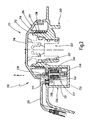
Figur 1 entsprechende Darstellung, jedoch mit einer elektromagnetisch gesteuerten Verdrehsicherung gemäß einem dritten Ausführungsbeispiel vorliegender Erfindung, und - Figur 4
- eine der
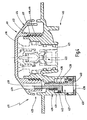
Figur 1 entsprechende Darstellung einer druckgesteuerten Verdrehsicherung, jedoch gemäß einem vierten Ausführungsbeispiel vorliegender Erfindung. - Die in der Zeichnung gemäß mehreren Ausführungsbeispielen dargestellte Abschraubsicherungsvorrichtung 10, 110, 210 bzw. 410 dient zum betriebsgesteuerten Verhindern des Abschraubens eines Verschlussdeckels 11, 111, 211 bzw. 411 vom Verschlussstutzen 12, 112, 212 bzw. 412 eines Behälters 13, 113, 213 bzw. 413, beispielsweise eines Kraftfahrzeugkühlers, dann, wenn aufgrund des Betriebszustandes des Behälters (erhöhter Druck bzw. Temperatur) das Abschrauben des Verschlussdeckels vom Behälterstutzen für den Benutzer Gefahren mitsich bringen kann.
- Der Verschlussdeckel 11, 111, 211, 411 besitzt ein Deckelaußenteil 14, 114, 214, 414 mit Griffelement 16, 116, 216, 416 das einstückig mit einem Verschlusselement 17, 117, 217, 417 versehen ist, welches hier ein Innengewinde 18, 118, 218, 418 zum Auf- und Abschrauben des Verschlussdeckels auf die bzw. von der Öffnung des mit einem Außengewinde 19, 119, 219, 419 versehenen Stutzens 12, 112, 212, 412 des Kraftfahrzeugkühlers 13, 113, 213, 413 oder sonstigen Behälters dient. Es versteht sich, dass das Verschlusselement 17, 117, 217, 417 statt mit einem Gewinde mit einem Bajonettverschlussteil versehen sein kann, das mit einem entsprechenden Bajonettverschlussteil am Stutzen verbunden werden kann. An der Innenseite des Griffelements 16, 116, 216, 416 ist konzentrisch zum Verschlusselement 17, 117, 217, 417 ein Deckelinnenteil 21, 121, 221, 421 hängend angeordnet. Das Deckelinnenteil 21, 121, 221, 421 ist gegenüber dem Griffelement 16, 116, 216, 416 des Deckelaußenteils 14, 114, 219, 414 verdrehbar jedoch axial festgehalten. Das Deckelinnenteil 21, 121, 221, 421 ist als Ventiltopf ausgebildet und nimmt eine lediglich gestrichelt schematisch dargestellte Überdruck/Unterdruck-Ventilanordnung 22, 122, 222, 422 auf, deren Überdruckventil einstufig oder zweistufig ansteuerbar ist.
- Die Abschraubsicherungsvorrichtung 10, 110, 210, 410 besitzt eine Verdrehsicherung 25, 125, 225, 425 die einen in einem innerhalb oder außerhalb des Behälters 13, 113, 213, 413 vorgesehenen Gehäuse 26, 126, 216, 426 angeordneten Antrieb 27, 127, 227, 427 besitzt, der einen Sperrbolzen 28, 128, 228, 428 zum Ineingriff bzw. Außereingriff bringen in bzw. aus einer Sperröffnung 29, 129, 229, 429 im Griffelement 16, 116, 216, 416 des Verschlussdeckels 11, 111, 211, 211, 411 bestätigt. Dabei ist der Antrieb 27, 127, 227, 427 bei den einzelnen Ausführungsbeispielen in Abhängigkeit von unterschiedlichen Vorgaben ansteuerbar.
- Beim Ausführungsbeispiel der
Figur 1 ist der Antrieb 27 vom im Behälter 13 gegebenen Innendruck ansteuerbar. Hierzu ist das den Antrieb 27 aufnehmende Gehäuse 26 in einem Bereich innerhalb des Behälters 13 und unterhalb des Außengewindes 19 des Stutzens 12 und einem Außenbereich des Griffelement 16 des Verschlussdeckels 11 gegenüberliegend angeordnet. Das Gehäuse 26 besitzt ein Zylinderteil 31, das einstückig von der Innenwandung des Behälters 13 nach Innen absteht und das von einem Deckelteil 32 verschlossen ist, der mit mehreren gleichmäßig verteilt angeordneten Verbindungsöffnungen 39 versehen ist. Innerhalb des Zylinderteils 31 ist ein Einsatz 33 angeordnet, der durch den Deckelteil 32 im Zylinderteil 31 eingeklemmt ist und der als Führungsteil für den Sperrbolzen 28 dient..Der Innerhalb des Gehäuses 26 axial beweglich angerodnete Sperrbolzen 28 durchdringt die den Gehäuseboden bildende Behälterwand und ist in diesem Bereich beispielsweise stiftartig rund. Innerhalb des Gehäuses 26 besitzt der Sperrbolzen 28 eine Verbreiterung mit einer Ringnut 34, in der eine den stiftartigen Bolzenbereich umgebende Druckfeder 36 aufgenommen ist, die sich einenends am Grund der Ringnut 34 und andernends am Einsatz 33 abstützt. Diese Druckfeder 36 drückt den Sperrbolzen 28 gegen eine vom Druck im Behälterinneren beaufschlagte Membran 40, die an ihrem Außenumfang zwischen dem Deckelteil 32 und dem Einsatz 33 druckdicht eingespannt ist. Wie den beiden Halbschnitten derFigur 1 entnehmen ist, ist die Membran 40 in ihrem Mittenbereich 37, gegen den der Sperrbolzen 28 gedrückt ist, entgegen der Wirkung der Druckfeder 36 dann auslenkbar ist, wenn der Druck im Inneren des Behälters 13 einen bestimmten Wert übersteigt. Dem aus dem Behälter 13 ragenden Ende des Sperrbolzens 28 gegenüberliegend ist das Griffelement 16 mit einer axialen Durchgangsöffnung 38 versehen, in die der Sperrbolzen 28 bei ausgelenkter Membran 40 eingreifen und somit eine Drehverriegelung zwischen Griffelement 16 und Behälterstutzen 12 bewirken kann. Die Durchgangsöffnung 38 im Griffelement 16 ist hier durchgehend, d.h. von der Außenseite her zugängig, um für Fachleute dennoch ein Entriegeln und ein demzufolge Öffnen des Verschlussdeckels 11 bewusst zu ermöglichen. - Das in
Figur 2 dargestellte Ausführungsbeispiel ähnelt dem inFigur 1 dargestellten, mit dem Unterschied, dass der Antrieb 127 im Gehäuse 126 in Abhängigkeit von der im Inneren des Behälters 113 auftretenden Temperatur thermisch gesteuert und angetrieben ist. Während die Bauteile Sperrbolzen 128, Druckfeder 136, Einsatz 133, Zylinderteil 131 konstruktiv im wesentlichen etwa gleich aufgebaut und lagemäßig angeordnet sind, besitzt der Antrieb 127 eine Thermokapsel 140, die einen Dehnstoff beinhaltet, der sich unter dem Einfluss von Wärme bei Temperaturerhöhung ausdehnt. Die Thermokapsel 140 stützt sich an der Innenseite des Deckelteils 132 ab. Auf der Thermokapsel 140 befindet sich eine Dichtmembran 141, deren Mittenbereich zwischen der Oberseite der Thermokapsel 140 und der gegenüberliegenden Unterseite des verbreiterten Bereichs des Sperrbolzen 128 angeordnet ist. Der Umfangsbereich der Dichtmembran 141 ist zwischen Deckelteil 132 und Einsatz 133 eingeklemmt bzw. eingespannt. Zum unmittelbaren Übertragen der Wärme aus dem Behälterinneren auf die Thermokapsel 140 bzw. deren Dehnstoff ist der Deckelteil 132 ebenso wie der Deckelteil 32 beim druckgesteuerten Antrieb 27 bzw. 40 mit über den Umfang vorzugsweise gleichmäßig verteilt angeordneten Verbindungsöffnungen 139 versehen. Auch die dem Gehäuse 126 bzw. dem Sperrbolzen 128 gegenüberliegende Druchgangsöffnung 138 im Griffelement 116 ist in etwa der selben Art und Meise ausgebildet. - Bei dem in
Figur 3 dargestellten Ausführungsbeispiel ist der Antrieb 227 durch einen Elektromagneten 245 gebildet, der in einem Gehäuse 226 vorgesehen ist, das ebenfalls einen an der Innenseite eines Behälterwandungsbereichs einstückig nach Innen in den Behälter hängenden Zylinderteil 231 aufweist. Der Zylinderteil 231 ist ebenfalls von einem Deckelteil 232 abgedeckt, wobei der Deckelteil 232 mit Anlage- und Fixierrippen 246 zum haltenden Aufnehmen des Elektromagneten 245 dient. Der,Elektromagnet 245 besitzt eine Spule 248, innerhalb der ein Sperrbolzen 228 als Anker in axialer Richtung beweglich ist. Der Sperrbolzen 228 durchdringt eine Öffnung in der Behälterwandung und ragt aus dem Behälter 213 einer entsprechenden Sperrbohrung 238 im Griffelement 216 gegenüberliegend. Innerhalb des Gehäuses 226 ist in der Behälterwandung eine feuchtigkeitsdichte Durchführung 249 vorgesehen, durch die ein Anschlusskabel 251 zum Elektromagneten 245 geführt ist. Das Anschlusskabel 251 führt zu einer dem Betriebszustand des Motors des Kraftfahrzeugs erfassenden nicht dargestellten Steuerung. - Das in
Figur 4 dargestellte Ausführungsbeispiel ähnelt wiederum dem inFigur 1 Dargestellten, wobei der Antrieb 427 im Gehäuse 426 ebenfalls in Abhängigkeit von dem im Inneren des Behälters 413 auftretenden Druck gesteuert ist. Dabei ist jedoch statt der Membran 40 nachFigur 1 ein Kolben 440 im Zylinderteil 431 des Gehäuses 426 gegen die Wirkung einer Druckfeder 436 axial beweglich angeordnet. Der Kolben 440 ist längs der Innenwandung des Zylinderteils 431 über einen Dichtungsring 442 druckdicht geführt. Der Kolben 440 ist mit einem konzentrischen axialen Sperrbolzen 428 einstückig versehen, den die Druckfeder 436 umgibt, die sich einenends am Kolben 440 und anderenends an einer inneren Ringfläche des Zylinderteils 431 abstützt, welche Ringfläche die Durchgangsbohrung des Gehäuses 426 umgibt, durch die der Sperrbolzen 428 dringt. Der Sperrbolzen 428 ist dann entgegen der Wirkung der Druckfeder 436 in eine axiale Durchgangsöffnung 438 im Griffelement 416 gedrückt, wenn der Druck im Inneren des Behälters 413 einen bestimmten Wert übersteigt. Bei nach oben geschobenem Kolben 440 bewirkt deshalb der Sperrbolzen 428 eine Drehverriegelung zwischen Griffelement 416 und Behälterstutzen 412. Auch bei diesem Ausführungsbeispiel ist die Durchgangsöffnung 438 im Griffelement 416 durchgehend, d.h. von der Außenseite her zugängig, um für Fachleute dennoch ein Entriegeln und ein dem zufolge Öffnen des Verschlussdeckels 411 bewusst zu ermöglichen. - Der Zylinderteil 431 des Gehäuses 426 ist an seinem inneren Ende von einem Deckel 432 abgedeckt, der den Zylinderteil 431 außenseitig verrastend übergreift. Der Deckelteil 432 ist bodenseitig mit einer hier mittig konzentrischen Verbindungsöffnung 439 versehen, die eine Übertragung der Druckverhältnisse im Innern des Behälters 413 auf den axial bewegbaren Kolben 440 ermöglicht.
- Während des Motorbetriebs wird sich die Kühlflüssigkeit im Behälter 13, 113, 213, 413 erwärmen, so dass dort die Temperatur bzw. der Druck ansteigt. Durch die unmittelbare Anordnung des Antriebs 14 bzw. 114 bzw. 414 nach den Ausführungsbeispielen der
Figuren 1 ,2 und4 im Behälterinneren wird bei Druckerhöhung gemäßFigur 1 , rechter Halbschnitt bzw.Figur 4 , linker Halbschnitt, die Membran 40 bzw. der Kolben 440 ausgelenkt und entgegen der Wirkung der auf die Verdrehsicherung 25 bzw. 425 wirkenden Druckfeder 36 bzw. 436 in Richtung des Pfeiles B axial bewegt, so dass der Sperrbolzen 28 bzw. 428 in die Sperröffnung 38 bzw. 438 greift. Beim Ausführungsbeispiel derFigur 2 , rechter Halbschnitt, wird aufgrund der Temperaturerhöhung der Dehnstoff ausgedehnt, so dass sich die Thermokapsel 140 in Richtung des Pfeiles B ebenfalls entgegen der auf die Verdrehsicherung wirkenden Druckfeder 136 axial dehnt, wobei durch diese Dehnungsbewegung der Sperrbolzen 128 in die Sperröffnung 138 gelangt. - Entsprechendes gilt für das Ausführungsbeispiel nach
Figur 3 , bei dem die Temperatur- bzw. Druckerhöhung im Behälter 213 mittelbar von elektrischen Motordaten, beispielsweise beim Abschalten des warmen Motors abgeleitet ist. Auch hier wird der Sperrbolzen 228 in die Sperröffnung 238 greifen. - Es versteht sich, dass dann, wenn sich die Betriebsstellung (Temperatur- bzw. Druckerhöhung), die unmittelbar oder mittelbar abgegriffen wird, zur Normal- bzw. Ausgangsstellung ändert, die Sperrwirkung wieder aufgehoben wird, indem der Sperrbolzen 28, 128, 228, 328, 428 unter der Wirkung der Druckfeder 36, 136, 236, 326, 426 zurückgeführt wird.
- Es versteht sich, dass bei dem Ausführungsbeispiel der
figuren 3 die Lage der Antriebsgehäuse 226 auch in jeweils anderer Weise (außen statt innen bzw. innen statt außen) vorgesehen sein kann. Entsprechendes gilt für die Lage des Sperrbolzens. - Des Weiteren ist es bei allen Ausführungsbeispielen möglich, zwischen dem Antrieb 26, 126, 226, 426 und dem von diesem auszulenkenden Sperrbolzen 28, 128, 228, 428 einen wippenartigen Kraftverstärker vorzusehen. ,
Claims (12)
- Abschraubsicherungsvorrichtung (10, 110, 210, 410) für einen auf einem ortsfesten Stutzen (12, 112, 212, 412) eines Behälters (13, 113, 213, 413), insbesondere Kraftfahrzeugkühlers, aufbringbaren bzw. aufgebrachten Verschlussdeckel (11, 111, 211, 411), der einen Deckelaußenteil (14, 114, 214, 414) mit Griffelement 16, 116, 216, 416) und mit mit einem Gegenverschlusselement (19, 119, 219, 419) des Stutzens (12, 112, 212, 412) verbindbaren Verschlusselement (17, 117, 217, 417) und einen Deckelinnenteil (21, 121, 221, 421) mit einer vorzugsweise in Überdruck/Unterdruckkombination ausgeführten Ventilanordnung (22, 122, 222, 422) aufweist, wobei eine Verdrehsicherung (25, 125, 225, 425) zwischen dem Deckelaußenteil (14, 114, 214, 414) und dem Stutzen 12, 112, 212, 412) wirkt und mittels eines von den Betriebsdaten im Behälter (13, 113, 213, 413) oder eines Motors angesteuerten Antriebs (27, 127, 227, 427) betätigbar ist, der in einem Gehäuse (26, 126, 226, 426) nahe dem Deckelaußenteil (14, 114, 214, 414) unterbracht ist, dadurch gekennzeichnet, dass das den Antrieb (27, 127, 227, 427) aufnehmende Gehäuse (26, 126, 226, 426) innerhalb des Behälters (13, 113, 213, 413) und unterhalb des Gegenverschlusselementes (19, 119, 219, 419) des Stutzens (12, 112, 212, 412) angeordnet ist, wobei das den Antrieb (27, 127, 227, 427) aufnehmende Gehäuse (26, 126, 226, 426) in die Behälterwandung intergriert ist, und durch einen' von der Behälterwandung abstehenden Zylinderteil (31, 131, 231, 431) und einen diesen verschließenden Deckelteil (32, 132, 232, 432) gebildet ist.
- Abschraubsicherungsvorrichtung nach Anspruch 1, dadurch gekennzeichnet, dass die Verdrehsicherung (25, 125, 225, 425) einen Sperrbolzen (28, 128, 228, 428) aufweist, der vom Antrieb (27, 127, 227, 427) in eine Sperrausnehmung (38, 138, 238, 438) des Deckelaußenteils (14, 114, 214 , 414) einrückbar ist.
- Abschraubsicherungsvorrichtung nach Anspruch 2, dadurch gekennzeichnet, dass der den Sperrbolzen (28, 128, 228, 428) beaufschlagende Antrieb (27, 127, 227, 427) einseitig wirkt und der Sperrbolzen in Gegenrichtung federbeaufschlagt ist.
- Abschraubsicherungsvorrichtung nach Anspruch 2, dadurch gekennzeichnet, dass der den Sperrbolzen (228) beaufschlagende Antrieb (227) doppelseitig wirkt.
- Abschraubsicherungsvorrichtung nach mindestens einem der Ansprüche 2 bis 4, dadurch gekennzeichnet, dass der Sperrbolzen (28, 128, 228, 428) vertikal gerichtet ist.
- Abschraubsicherungsvorrichtung nach mindestens einem der Ansprüche 1 bis 5, dadurch gekennzeichnet, dass der Antrieb (27, 427) druckgesteuert ist und durch eine mit dem Behälterinneren in Verbindung stehende Membran (40) oder Kolben (440) gebildet ist.
- Abschraubsicherungsvorrichtung nach mindestens einem der Ansprüche 1 bis 5, dadurch gekennzeichnet, dass der Antrieb (127) thermisch gesteuert ist und durch eine mit dem Behälterinneren in Verbindung stehende Dehnstoffkapsel (140) gebildet ist.
- Abschraubsicherungsvorrichtung nach mindestens einem der Ansprüche 1 bis 5, dadurch gekennzeichnet, dass der Antrieb (227) in Abhängigkeit von den Motordaten elektromagnetisch gesteuert ist, wobei der Sperrbolzen (228) Teil eines Elektromagneten (245) ist.
- Abschraubsicherungsvorrichtung nach mindestens einem der Ansprüche 1 bis 7, dadurch gekennzeichnet, dass das Gehäuse (26, 126, 426) mit zum Behälterinneren weisenden axialen Öffnungen (39, 139, 439) versehen ist.
- Abschraubsicherungsvorrichtung nach mindestens einem der Ansprüche 1, 6 oder 9, dadurch gekennzeichnet, dass die Membran (40) bzw. der Kolben (440) im Gehäuse (26) druckdicht eingespannt bzw. axial geführt ist.
- Abschraubsicherungsvorrichtung nach Anspruch 10, dadurch gekennzeichnet, dass die Membran (40) zwischen einem Umfangsrand des Gehäuses (26) und einem Deckelteil (32) druckdicht eingespannt ist.
- Abschraubsicherungsvorrichtung nach den Ansprüchen 9 und/oder 11, dadurch gekennzeichnet, dass der Deckelteil (32, 132, 432) mit den axiale Öffnungen (39, 139, 439) versehen. ist
Applications Claiming Priority (3)
| Application Number | Priority Date | Filing Date | Title |
|---|---|---|---|
| DE10164669A DE10164669A1 (de) | 2001-12-22 | 2001-12-22 | Abschraubsicherungsvorrichtung für Behälter |
| DE10164669 | 2001-12-22 | ||
| PCT/EP2002/014130 WO2003056155A1 (de) | 2001-12-22 | 2002-12-12 | ABSCHRAUBSICHERUNGSVORRICHTUNG F!UR BEHÄLTER |
Publications (2)
| Publication Number | Publication Date |
|---|---|
| EP1456516A1 EP1456516A1 (de) | 2004-09-15 |
| EP1456516B1 true EP1456516B1 (de) | 2008-10-08 |
Family
ID=7711262
Family Applications (1)
| Application Number | Title | Priority Date | Filing Date |
|---|---|---|---|
| EP02796617A Expired - Lifetime EP1456516B1 (de) | 2001-12-22 | 2002-12-12 | Abschraubsicherungsvorrichtung für behälter |
Country Status (7)
| Country | Link |
|---|---|
| US (1) | US20050121453A1 (de) |
| EP (1) | EP1456516B1 (de) |
| AT (1) | ATE410590T1 (de) |
| BR (1) | BR0215349A (de) |
| CA (1) | CA2471118A1 (de) |
| DE (2) | DE10164669A1 (de) |
| WO (1) | WO2003056155A1 (de) |
Families Citing this family (7)
| Publication number | Priority date | Publication date | Assignee | Title |
|---|---|---|---|---|
| DE20211232U1 (de) * | 2002-07-18 | 2003-11-20 | Reutter, Heinrich, 71336 Waiblingen | Verschlussdeckel |
| WO2004027233A1 (en) | 2002-09-18 | 2004-04-01 | Sundaram Fasteners Limited | A safety-cap system for an engine cooling device and a method thereof |
| DE10246590A1 (de) * | 2002-10-05 | 2004-04-22 | Daimlerchrysler Ag | Behälter für flüssige und/oder gasförmige Medien und Kühlsystem für eine Brennkraftmaschine |
| DE202004001333U1 (de) | 2004-01-22 | 2005-06-02 | Reutter Metallwarenfabrik Gmbh | Abschraubsicherungsvorrichtung für Behälter |
| DE102012218392A1 (de) * | 2012-10-09 | 2014-04-10 | Reutter Gmbh | Druck- oder temperaturgesteuertes Wegeventil für einen Ausgleichsbehälter und Kühlsystem einer Brennkraftmaschine |
| CN113291609B (zh) * | 2021-05-07 | 2023-05-09 | 南京唐壹信息科技有限公司 | 一种防污染的医用线体包装盒 |
| DE102025109293B3 (de) | 2025-03-11 | 2026-05-13 | Audi Aktiengesellschaft | Ausgleichsbehälter für einen Fluidkreislauf eines Kraftfahrzeugs |
Family Cites Families (7)
| Publication number | Priority date | Publication date | Assignee | Title |
|---|---|---|---|---|
| US3587912A (en) * | 1968-08-23 | 1971-06-28 | Nippon Denso Co | Pressure cap unit with pressure releasing means for radiators of internal combustion engines |
| US4457327A (en) * | 1982-07-26 | 1984-07-03 | Bemis Manufacturing Company | Temperature responsive valve mechanism |
| FR2675570A1 (fr) * | 1991-04-18 | 1992-10-23 | Journee Paul Sa | Dispositif de securite pour un bouchon de fermeture d'un echangeur thermique. |
| US5248052A (en) * | 1992-07-31 | 1993-09-28 | Mellinger Larry L | Apparatus for automatically releasing the super-atmospheric pressure of an engine cooling system in response to turning off the engine and preventing the buildup of pressure while the engine is off |
| WO1995032904A1 (de) * | 1994-06-01 | 1995-12-07 | Reutter Heiner | Auf einem behälterstutzen befestigbarer verschlussdeckel |
| IT236893Y1 (it) * | 1995-05-23 | 2000-08-31 | Miralfin Srl | Tappo di sicurezza per contenitori in pressione |
| EP0995888A1 (de) * | 1998-10-23 | 2000-04-26 | Behr Thermot-tronik Italia S.p.A. | Sicherheitsverschlussdeckel, inbesondere für den Kühlmittelkreislauf einer Brennkraftmaschine für Kraftwagen |
-
2001
- 2001-12-22 DE DE10164669A patent/DE10164669A1/de not_active Withdrawn
-
2002
- 2002-12-12 EP EP02796617A patent/EP1456516B1/de not_active Expired - Lifetime
- 2002-12-12 DE DE50212882T patent/DE50212882D1/de not_active Expired - Lifetime
- 2002-12-12 AT AT02796617T patent/ATE410590T1/de not_active IP Right Cessation
- 2002-12-12 BR BR0215349-1A patent/BR0215349A/pt not_active Application Discontinuation
- 2002-12-12 WO PCT/EP2002/014130 patent/WO2003056155A1/de not_active Ceased
- 2002-12-12 CA CA002471118A patent/CA2471118A1/en not_active Abandoned
- 2002-12-12 US US10/499,677 patent/US20050121453A1/en not_active Abandoned
Also Published As
| Publication number | Publication date |
|---|---|
| DE10164669A1 (de) | 2003-07-03 |
| WO2003056155A1 (de) | 2003-07-10 |
| BR0215349A (pt) | 2004-11-16 |
| DE50212882D1 (de) | 2008-11-20 |
| US20050121453A1 (en) | 2005-06-09 |
| EP1456516A1 (de) | 2004-09-15 |
| CA2471118A1 (en) | 2003-07-10 |
| ATE410590T1 (de) | 2008-10-15 |
Similar Documents
| Publication | Publication Date | Title |
|---|---|---|
| EP1682801B1 (de) | Elektromagnetisches ventil | |
| EP4194737B1 (de) | Druckbehälter und verfahren zu dessen befüllen | |
| EP1468172A1 (de) | Verschlussdeckel für kraftfahrzeugkühler | |
| EP1303687B1 (de) | Verschlussdeckel mit verdrehsicherung | |
| EP1303686B1 (de) | Verschlussdeckel für kraftfahrzeugkühler | |
| EP1233158B1 (de) | Verschlussdeckel für Kraftfahrzeugkühler | |
| EP1942292A1 (de) | Sicherheitsverschluss für unter Dampfdruck stehende Behälter von Haushaltsgeräten | |
| DE10034761A1 (de) | Verschlussdeckel | |
| EP1456516A1 (de) | ABSCHRAUBSICHERUNGSVORRICHTUNG F!UR BEH LTER | |
| EP1456514B1 (de) | Verschlussdeckel für kraftfahrzeugkühler | |
| EP1402157B1 (de) | Verschlussdeckel mit abschraubsicherung | |
| DE10361781B4 (de) | Elektromagnetisches Ventil | |
| EP1678413B1 (de) | Verschlussdeckel für kraftfahrzeugkühler | |
| EP1456515B1 (de) | Verschlussdeckel für kraftfahrzeugkühler | |
| EP1180206B1 (de) | Verschlussdeckel für kraftfahrzeugkühler | |
| DE10034762A1 (de) | Verschlussdeckel | |
| DE19732885B4 (de) | Verschlussdeckel mit Sicherheitsverriegelung für einen Behälter | |
| DE10246590A1 (de) | Behälter für flüssige und/oder gasförmige Medien und Kühlsystem für eine Brennkraftmaschine | |
| EP1706611B1 (de) | Abschraubsicherungsvorrichtung für behälter | |
| DE60202334T2 (de) | Sicherheitsverschluss für Druckbehälter | |
| DE19648683A1 (de) | Druckmittelzylinder mit einem Entlüftungselement mit axialer Elastomerdichtung |
Legal Events
| Date | Code | Title | Description |
|---|---|---|---|
| PUAI | Public reference made under article 153(3) epc to a published international application that has entered the european phase |
Free format text: ORIGINAL CODE: 0009012 |
|
| 17P | Request for examination filed |
Effective date: 20040513 |
|
| AK | Designated contracting states |
Kind code of ref document: A1 Designated state(s): AT BE BG CH CY CZ DE DK EE ES FI FR GB GR IE IT LI LU MC NL PT SE SI SK TR |
|
| 17Q | First examination report despatched |
Effective date: 20070601 |
|
| GRAP | Despatch of communication of intention to grant a patent |
Free format text: ORIGINAL CODE: EPIDOSNIGR1 |
|
| GRAS | Grant fee paid |
Free format text: ORIGINAL CODE: EPIDOSNIGR3 |
|
| GRAA | (expected) grant |
Free format text: ORIGINAL CODE: 0009210 |
|
| AK | Designated contracting states |
Kind code of ref document: B1 Designated state(s): AT BE BG CH CY CZ DE DK EE ES FI FR GB GR IE IT LI LU MC NL PT SE SI SK TR |
|
| REG | Reference to a national code |
Ref country code: GB Ref legal event code: FG4D Free format text: NOT ENGLISH |
|
| REG | Reference to a national code |
Ref country code: CH Ref legal event code: EP |
|
| REG | Reference to a national code |
Ref country code: IE Ref legal event code: FG4D Free format text: LANGUAGE OF EP DOCUMENT: GERMAN |
|
| REF | Corresponds to: |
Ref document number: 50212882 Country of ref document: DE Date of ref document: 20081120 Kind code of ref document: P |
|
| PG25 | Lapsed in a contracting state [announced via postgrant information from national office to epo] |
Ref country code: SI Free format text: LAPSE BECAUSE OF FAILURE TO SUBMIT A TRANSLATION OF THE DESCRIPTION OR TO PAY THE FEE WITHIN THE PRESCRIBED TIME-LIMIT Effective date: 20081008 |
|
| NLV1 | Nl: lapsed or annulled due to failure to fulfill the requirements of art. 29p and 29m of the patents act | ||
| PG25 | Lapsed in a contracting state [announced via postgrant information from national office to epo] |
Ref country code: ES Free format text: LAPSE BECAUSE OF FAILURE TO SUBMIT A TRANSLATION OF THE DESCRIPTION OR TO PAY THE FEE WITHIN THE PRESCRIBED TIME-LIMIT Effective date: 20090119 Ref country code: BG Free format text: LAPSE BECAUSE OF FAILURE TO SUBMIT A TRANSLATION OF THE DESCRIPTION OR TO PAY THE FEE WITHIN THE PRESCRIBED TIME-LIMIT Effective date: 20090108 |
|
| PG25 | Lapsed in a contracting state [announced via postgrant information from national office to epo] |
Ref country code: PT Free format text: LAPSE BECAUSE OF FAILURE TO SUBMIT A TRANSLATION OF THE DESCRIPTION OR TO PAY THE FEE WITHIN THE PRESCRIBED TIME-LIMIT Effective date: 20090218 Ref country code: NL Free format text: LAPSE BECAUSE OF FAILURE TO SUBMIT A TRANSLATION OF THE DESCRIPTION OR TO PAY THE FEE WITHIN THE PRESCRIBED TIME-LIMIT Effective date: 20081008 Ref country code: FI Free format text: LAPSE BECAUSE OF FAILURE TO SUBMIT A TRANSLATION OF THE DESCRIPTION OR TO PAY THE FEE WITHIN THE PRESCRIBED TIME-LIMIT Effective date: 20081008 |
|
| BERE | Be: lapsed |
Owner name: REUTTER, HEINRICH Effective date: 20081231 |
|
| REG | Reference to a national code |
Ref country code: IE Ref legal event code: FD4D |
|
| PG25 | Lapsed in a contracting state [announced via postgrant information from national office to epo] |
Ref country code: EE Free format text: LAPSE BECAUSE OF FAILURE TO SUBMIT A TRANSLATION OF THE DESCRIPTION OR TO PAY THE FEE WITHIN THE PRESCRIBED TIME-LIMIT Effective date: 20081008 Ref country code: DK Free format text: LAPSE BECAUSE OF FAILURE TO SUBMIT A TRANSLATION OF THE DESCRIPTION OR TO PAY THE FEE WITHIN THE PRESCRIBED TIME-LIMIT Effective date: 20081008 Ref country code: MC Free format text: LAPSE BECAUSE OF NON-PAYMENT OF DUE FEES Effective date: 20081231 Ref country code: IE Free format text: LAPSE BECAUSE OF FAILURE TO SUBMIT A TRANSLATION OF THE DESCRIPTION OR TO PAY THE FEE WITHIN THE PRESCRIBED TIME-LIMIT Effective date: 20081008 |
|
| REG | Reference to a national code |
Ref country code: CH Ref legal event code: PL |
|
| PLBE | No opposition filed within time limit |
Free format text: ORIGINAL CODE: 0009261 |
|
| STAA | Information on the status of an ep patent application or granted ep patent |
Free format text: STATUS: NO OPPOSITION FILED WITHIN TIME LIMIT |
|
| PG25 | Lapsed in a contracting state [announced via postgrant information from national office to epo] |
Ref country code: CZ Free format text: LAPSE BECAUSE OF FAILURE TO SUBMIT A TRANSLATION OF THE DESCRIPTION OR TO PAY THE FEE WITHIN THE PRESCRIBED TIME-LIMIT Effective date: 20081008 Ref country code: SE Free format text: LAPSE BECAUSE OF FAILURE TO SUBMIT A TRANSLATION OF THE DESCRIPTION OR TO PAY THE FEE WITHIN THE PRESCRIBED TIME-LIMIT Effective date: 20090108 Ref country code: IT Free format text: LAPSE BECAUSE OF FAILURE TO SUBMIT A TRANSLATION OF THE DESCRIPTION OR TO PAY THE FEE WITHIN THE PRESCRIBED TIME-LIMIT Effective date: 20081008 |
|
| 26N | No opposition filed |
Effective date: 20090709 |
|
| GBPC | Gb: european patent ceased through non-payment of renewal fee |
Effective date: 20090108 |
|
| PG25 | Lapsed in a contracting state [announced via postgrant information from national office to epo] |
Ref country code: BE Free format text: LAPSE BECAUSE OF NON-PAYMENT OF DUE FEES Effective date: 20081231 Ref country code: SK Free format text: LAPSE BECAUSE OF FAILURE TO SUBMIT A TRANSLATION OF THE DESCRIPTION OR TO PAY THE FEE WITHIN THE PRESCRIBED TIME-LIMIT Effective date: 20081008 |
|
| REG | Reference to a national code |
Ref country code: FR Ref legal event code: ST Effective date: 20090831 |
|
| PG25 | Lapsed in a contracting state [announced via postgrant information from national office to epo] |
Ref country code: LI Free format text: LAPSE BECAUSE OF NON-PAYMENT OF DUE FEES Effective date: 20081231 Ref country code: CH Free format text: LAPSE BECAUSE OF NON-PAYMENT OF DUE FEES Effective date: 20081231 |
|
| PG25 | Lapsed in a contracting state [announced via postgrant information from national office to epo] |
Ref country code: GB Free format text: LAPSE BECAUSE OF NON-PAYMENT OF DUE FEES Effective date: 20090108 |
|
| PG25 | Lapsed in a contracting state [announced via postgrant information from national office to epo] |
Ref country code: FR Free format text: LAPSE BECAUSE OF NON-PAYMENT OF DUE FEES Effective date: 20081231 |
|
| PG25 | Lapsed in a contracting state [announced via postgrant information from national office to epo] |
Ref country code: AT Free format text: LAPSE BECAUSE OF NON-PAYMENT OF DUE FEES Effective date: 20081212 |
|
| PG25 | Lapsed in a contracting state [announced via postgrant information from national office to epo] |
Ref country code: CY Free format text: LAPSE BECAUSE OF FAILURE TO SUBMIT A TRANSLATION OF THE DESCRIPTION OR TO PAY THE FEE WITHIN THE PRESCRIBED TIME-LIMIT Effective date: 20081008 Ref country code: LU Free format text: LAPSE BECAUSE OF NON-PAYMENT OF DUE FEES Effective date: 20081212 |
|
| PG25 | Lapsed in a contracting state [announced via postgrant information from national office to epo] |
Ref country code: TR Free format text: LAPSE BECAUSE OF FAILURE TO SUBMIT A TRANSLATION OF THE DESCRIPTION OR TO PAY THE FEE WITHIN THE PRESCRIBED TIME-LIMIT Effective date: 20081008 |
|
| PG25 | Lapsed in a contracting state [announced via postgrant information from national office to epo] |
Ref country code: GR Free format text: LAPSE BECAUSE OF FAILURE TO SUBMIT A TRANSLATION OF THE DESCRIPTION OR TO PAY THE FEE WITHIN THE PRESCRIBED TIME-LIMIT Effective date: 20090109 |
|
| PGFP | Annual fee paid to national office [announced via postgrant information from national office to epo] |
Ref country code: DE Payment date: 20150224 Year of fee payment: 13 |
|
| REG | Reference to a national code |
Ref country code: DE Ref legal event code: R119 Ref document number: 50212882 Country of ref document: DE |
|
| PG25 | Lapsed in a contracting state [announced via postgrant information from national office to epo] |
Ref country code: DE Free format text: LAPSE BECAUSE OF NON-PAYMENT OF DUE FEES Effective date: 20160701 |