EP1456535B1 - Wind turbine in parked position - Google Patents
Wind turbine in parked position Download PDFInfo
- Publication number
- EP1456535B1 EP1456535B1 EP02793100A EP02793100A EP1456535B1 EP 1456535 B1 EP1456535 B1 EP 1456535B1 EP 02793100 A EP02793100 A EP 02793100A EP 02793100 A EP02793100 A EP 02793100A EP 1456535 B1 EP1456535 B1 EP 1456535B1
- Authority
- EP
- European Patent Office
- Prior art keywords
- rotor
- rotor blade
- blades
- power plant
- wind power
- Prior art date
- Legal status (The legal status is an assumption and is not a legal conclusion. Google has not performed a legal analysis and makes no representation as to the accuracy of the status listed.)
- Expired - Lifetime
Links
- 238000000034 method Methods 0.000 claims abstract description 17
- 230000005484 gravity Effects 0.000 description 4
- 230000005284 excitation Effects 0.000 description 2
- 238000009420 retrofitting Methods 0.000 description 2
- 238000004088 simulation Methods 0.000 description 2
- 230000003068 static effect Effects 0.000 description 2
- 230000004913 activation Effects 0.000 description 1
- 230000006978 adaptation Effects 0.000 description 1
- 230000005540 biological transmission Effects 0.000 description 1
- 238000004364 calculation method Methods 0.000 description 1
- 230000010355 oscillation Effects 0.000 description 1
Images





Classifications
-
- F—MECHANICAL ENGINEERING; LIGHTING; HEATING; WEAPONS; BLASTING
- F03—MACHINES OR ENGINES FOR LIQUIDS; WIND, SPRING, OR WEIGHT MOTORS; PRODUCING MECHANICAL POWER OR A REACTIVE PROPULSIVE THRUST, NOT OTHERWISE PROVIDED FOR
- F03D—WIND MOTORS
- F03D7/00—Controlling wind motors
- F03D7/02—Controlling wind motors the wind motors having rotation axis substantially parallel to the air flow entering the rotor
- F03D7/022—Adjusting aerodynamic properties of the blades
- F03D7/024—Adjusting aerodynamic properties of the blades of individual blades
-
- F—MECHANICAL ENGINEERING; LIGHTING; HEATING; WEAPONS; BLASTING
- F03—MACHINES OR ENGINES FOR LIQUIDS; WIND, SPRING, OR WEIGHT MOTORS; PRODUCING MECHANICAL POWER OR A REACTIVE PROPULSIVE THRUST, NOT OTHERWISE PROVIDED FOR
- F03D—WIND MOTORS
- F03D7/00—Controlling wind motors
- F03D7/02—Controlling wind motors the wind motors having rotation axis substantially parallel to the air flow entering the rotor
- F03D7/022—Adjusting aerodynamic properties of the blades
- F03D7/0224—Adjusting blade pitch
-
- F—MECHANICAL ENGINEERING; LIGHTING; HEATING; WEAPONS; BLASTING
- F03—MACHINES OR ENGINES FOR LIQUIDS; WIND, SPRING, OR WEIGHT MOTORS; PRODUCING MECHANICAL POWER OR A REACTIVE PROPULSIVE THRUST, NOT OTHERWISE PROVIDED FOR
- F03D—WIND MOTORS
- F03D7/00—Controlling wind motors
- F03D7/02—Controlling wind motors the wind motors having rotation axis substantially parallel to the air flow entering the rotor
- F03D7/0264—Controlling wind motors the wind motors having rotation axis substantially parallel to the air flow entering the rotor for stopping; controlling in emergency situations
- F03D7/0268—Parking or storm protection
-
- F—MECHANICAL ENGINEERING; LIGHTING; HEATING; WEAPONS; BLASTING
- F03—MACHINES OR ENGINES FOR LIQUIDS; WIND, SPRING, OR WEIGHT MOTORS; PRODUCING MECHANICAL POWER OR A REACTIVE PROPULSIVE THRUST, NOT OTHERWISE PROVIDED FOR
- F03D—WIND MOTORS
- F03D7/00—Controlling wind motors
- F03D7/02—Controlling wind motors the wind motors having rotation axis substantially parallel to the air flow entering the rotor
- F03D7/0296—Controlling wind motors the wind motors having rotation axis substantially parallel to the air flow entering the rotor to prevent, counteract or reduce noise emissions
-
- F—MECHANICAL ENGINEERING; LIGHTING; HEATING; WEAPONS; BLASTING
- F05—INDEXING SCHEMES RELATING TO ENGINES OR PUMPS IN VARIOUS SUBCLASSES OF CLASSES F01-F04
- F05B—INDEXING SCHEME RELATING TO WIND, SPRING, WEIGHT, INERTIA OR LIKE MOTORS, TO MACHINES OR ENGINES FOR LIQUIDS COVERED BY SUBCLASSES F03B, F03D AND F03G
- F05B2260/00—Function
- F05B2260/70—Adjusting of angle of incidence or attack of rotating blades
- F05B2260/74—Adjusting of angle of incidence or attack of rotating blades by turning around an axis perpendicular the rotor centre line
-
- F—MECHANICAL ENGINEERING; LIGHTING; HEATING; WEAPONS; BLASTING
- F05—INDEXING SCHEMES RELATING TO ENGINES OR PUMPS IN VARIOUS SUBCLASSES OF CLASSES F01-F04
- F05B—INDEXING SCHEME RELATING TO WIND, SPRING, WEIGHT, INERTIA OR LIKE MOTORS, TO MACHINES OR ENGINES FOR LIQUIDS COVERED BY SUBCLASSES F03B, F03D AND F03G
- F05B2260/00—Function
- F05B2260/70—Adjusting of angle of incidence or attack of rotating blades
- F05B2260/76—Adjusting of angle of incidence or attack of rotating blades the adjusting mechanism using auxiliary power sources
-
- F—MECHANICAL ENGINEERING; LIGHTING; HEATING; WEAPONS; BLASTING
- F05—INDEXING SCHEMES RELATING TO ENGINES OR PUMPS IN VARIOUS SUBCLASSES OF CLASSES F01-F04
- F05B—INDEXING SCHEME RELATING TO WIND, SPRING, WEIGHT, INERTIA OR LIKE MOTORS, TO MACHINES OR ENGINES FOR LIQUIDS COVERED BY SUBCLASSES F03B, F03D AND F03G
- F05B2260/00—Function
- F05B2260/96—Preventing, counteracting or reducing vibration or noise
-
- Y—GENERAL TAGGING OF NEW TECHNOLOGICAL DEVELOPMENTS; GENERAL TAGGING OF CROSS-SECTIONAL TECHNOLOGIES SPANNING OVER SEVERAL SECTIONS OF THE IPC; TECHNICAL SUBJECTS COVERED BY FORMER USPC CROSS-REFERENCE ART COLLECTIONS [XRACs] AND DIGESTS
- Y02—TECHNOLOGIES OR APPLICATIONS FOR MITIGATION OR ADAPTATION AGAINST CLIMATE CHANGE
- Y02E—REDUCTION OF GREENHOUSE GAS [GHG] EMISSIONS, RELATED TO ENERGY GENERATION, TRANSMISSION OR DISTRIBUTION
- Y02E10/00—Energy generation through renewable energy sources
- Y02E10/70—Wind energy
- Y02E10/72—Wind turbines with rotation axis in wind direction
Definitions
- the invention relates to a method for operating a wind power plant with a rotor having at least two rotor blades rotatable in a rotor blade plane about a common rotor axis, whereof each can be swiveled about a swivel axis running roughly parallel to its longitudinal axis which is transverse, preferably approximately perpendicular to the rotor axis, in which the setting or pitch angles of the rotor blades are set with respect to the rotor blade plane by swiveling about a swivel axis as a function of the operating and in particular wind conditions, and to a wind power plant operated according to such a method.
- Wind power plants in general, comprise a tower, a nacelle at the tip of the tower rotatable around a rotation axis running essentially in the direction of gravity and a rotor rotatable around a rotor axis running essentially perpendicular to the direction of gravity.
- the nacelle and therewith also the rotor blade plane can be rotated around the rotation axis running essentially in the direction of gravity to achieve optimal operating conditions at varying wind directions.
- the rotational speed of common wind power plants with fixed setting of pitch angles of the rotor blades in respect to the rotor blade plane is limited by the stall-effect.
- DE 196 26 402 describes a method for pitching the rotor blades of a wind turbine in case of grid failure or excess wind speeds.
- the method is adapted for active stall wind turbines in that, in a first step, the rotor blades are actively driven to a stall position having a negative blade angle. In a final "parking position" of the rotor blades, all rotor blades are in a feathered position. For this purpose, the rotor blades are pitched, one after another, from the stall position into the feathered position. Thus, the blades in the stall position brake the rotor during the pitching of the other rotor blade.
- EP 0 709 571 describes a parking position for a two-bladed wind rotor of a wind turbine in which the tip ends of both rotor blades can be rotated about the longitudinal axis of the blades.
- the pitch angle of the first and second rotor blades is different in the parking position so that only one rotor blade exerts a torque.
- the methods described herein reduce damage to wind power plants at high wind speeds.
- this is solved by setting in the parking position of the rotor the setting or pitch angle of at least two rotor blades at different values.
- the invention is based on recognizing that by carrying out known methods at high wind loads, the observed damage is not caused by static loading of the wind power plant, but is caused by the excitation of vibrations of the rotor blades in the parking positions through the wind flow.
- the excitation of the vibrations result in coupled oscillations with corresponding resonance phenomena which cause the observed damage.
- the inventive solution to the above described problems when operating so-called pitch-plants with adjustable rotor blades is in particular constructively simple, since it does not require any changes to the rotor blades but only a corresponding control of the swiveling of the rotor blades in the parking position.
- the inventive method can be implemented by retrofitting already existing wind power plants with comparably little effort, since a replacement of the rotor blades is not necessary.
- the pitch angle in the parking position for one rotor blade is set at a value of more than 90° and for another rotor blade at a value of less than 90°, since then they would generate opposing torque which would prevent excessive stress of the brake system which, in general, is used to secure the rotor in the parking position.
- predetermined pitch angles of the rotor blades are automatically set to exceed a predetermined wind speed.
- a wind power plant suitable for performing such a method with a rotor with at least two rotor blades rotatable about a common rotor axis in a rotor blade plane, a drive mechanism for setting the pitch angles of the rotor blades with respect to the rotor blade plane and a control device operable for controlling the drive mechanism, is essentially characterized in that the drive mechanism for setting different pitch angles for at least two rotor blades is controllable.
- a limit switch operable on reaching a predetermined pitch angle with respect to the rotor blade plane is associated with each rotor blade.
- the driving element associated with this rotor blade is switched off, to ensure the desired parking position is reached when there is an emergency switch off of the wind power plant.
- each rotor blade can be associated with a control cam for, operating the limit switch, the position of which with respect to the rotor blade can be selected differently for each rotor blade corresponding to the desired pitch angle of the respective rotor blade.
- wind power plants according to the invention can be manufactured with little technical effort by simply retrofitting existing wind power plants.
- the control device which is responsible for setting the pitch angle of the rotor blades is exchanged and/or the generally already present control cams for the single rotor blades are differently arranged.
- FIG. 1 A schematic front view of a wind turbine 1 is shown in Fig. 1.
- the three rotor blades 5 are arranged in a rotor blade plane around the rotor hub 4 which is attached to the cabin or nacelle 3 of the wind turbine.
- the angle between two adjacent rotor blades is equal and, in the specific example shown, 120°.
- the lines A-A, B-B, C-C denote top side view along the rotor blade axis.
- Fig. 2 which is a top side view of the wind turbine tower.
- Rotor axis 6 of the turbine runs perpendicular to rotor blade plane in which the rotor blades are arranged.
- the rotor hub 4 is rotatable and attached to nacelle 3.
- On top of rotor hub 4 side sectional views of all three rotor blades along lines A-A, B-B and C-C are shown. Each sectional view represents the moment at which the respective rotor blade has reached its top position.
- rotor blade A-A is approximately parallel to the wind direction.
- the rotor blade is set at a pitch angle of about 90°.
- the pitch angle of rotor blade B-B is smaller than 90° and the pitch angle of rotor blade C-C is bigger than 90°.
- the deviation of rotor blades B-B and C-C from the A-A line are opposing to each other. They can be equal in size but they can also be different.
- Fig. 3 shows a perspective view of a rotor blade bearing flange of the rotor hub with a removed blade.
- the pitch drive 8 which is firmly fixed to rotor hub 4 is mounted inside the hub.
- Drive element 10 of pitch drive 8 is a gear wheel which interacts with the inner gear rim of flange 12.
- Flange 12 which is firmly attached to a rotor blade is rotatably located within rotor hub 4.
- pitch drive 8 enables a swiveling movement of its corresponding rotor blade whereby the swivel axis of the rotor blade is roughly parallel to the longitudinal axis of the blade.
- Fig 3 further shows a limit switch 14 which is activated by control cam 16.
- control cam 16 is connected to rotatable flange 12 of the rotor blade. It is assumed that the rotor blade is turned clockwise. Thus, in Fig. 3 the front end 16a of control cam 16 has already passed limit switch 14. The operation of the limit switch 14 interacting with the control cam 16 is explained subsequently in more detail. At a first stage, it is assumed that the control cam is located in a position where it has not yet engaged with the limit switch. If, for example, flange 12 of the rotor blade is viewn as clock, control cam 16 would e.g. be located roughly between 4 and 5 o'clock.
- pitch drive 8 will cause gear wheel 10 to rotate and, consequently, will cause flange 12 to turn clockwise towards 7 o'clock.
- the pitch drive will be switched off.
- the rotor blade will not come to an instantaneous halt but could continue to move for a little while. This is not obligatory but depends primarily on the setting of the control device which operates the pitch drive.
- Fig. 3 only shows one example of a possible embodiment.
- each rotor blade has its own independent pitch drive.
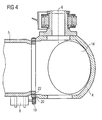
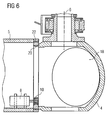
- Figs 4 to 7 show a variety of options to arrange rotor blade 5, pitch drive 8 and rotor hub 4 with respect to each other.
- Figs. 4 to 7 are sectional views of the rotor perpendicular to the rotor blade plane.
- Rotor hub 4 is attached to rotor axis 6 of the rotor.
- One rotor blade extends to the left side of the rotor hub.
- Opening 18 shows the flange opening at an angle of 120°. Onto this opening, the other rotor blade is attached but not shown in this sketch due to simplification.
- the rotor blade shown is connected with rotor hub 4.
- Pitch drive 8 is connected to rotor blade 5 and its drive element 10 interacts with an outer gear rim 20 of hub 4.
- bearing 20 allows a rotational movement of the rotor blade.
- Fig. 5 the inner end of the rotor blade encompasses a projecting portion of rotor hub 4.
- Pitch drive 8 is attached to rotor hub 4 and swivels the rotor blade by interacting with an outer gear rim 20 of rotor blade 5.
- pitch drive 8 can be arranged within rotor blade 4 and interacts with an inner gear rim 24 of rotor hub 4 as shown in Fig. 6.
- Fig. 7 shows again a different arrangement of a pitch drive for a rotor blade.
- Fig 8a and 8b show hydraulic pitch drives.
- Hydraulic pitch drive 26 is connected at one end with the rotor hub and at the other end hydraulic pitch drive 26 is connected with a plate 28 of the rotor blade.
- the eccentric arrangement of the hydraulic pitch drives causes the rotor blade to turn with respect to rotor hub 4.
- Fig. 9 shows a tooth belt driven pitch drive which causes a rotor blade having an inner end encompassing a projecting portion of a rotor hub to turn the rotor blade around rotor hub 4.
Landscapes
- Engineering & Computer Science (AREA)
- Life Sciences & Earth Sciences (AREA)
- Sustainable Development (AREA)
- Sustainable Energy (AREA)
- Chemical & Material Sciences (AREA)
- Combustion & Propulsion (AREA)
- Mechanical Engineering (AREA)
- General Engineering & Computer Science (AREA)
- Physics & Mathematics (AREA)
- Fluid Mechanics (AREA)
- Wind Motors (AREA)
Applications Claiming Priority (3)
| Application Number | Priority Date | Filing Date | Title |
|---|---|---|---|
| DE10162942 | 2001-12-20 | ||
| DE10162942A DE10162942A1 (de) | 2001-12-20 | 2001-12-20 | Verfahren zum Betreiben einer Windkraftanlage und Windkraftanlage |
| PCT/EP2002/014667 WO2003054388A1 (en) | 2001-12-20 | 2002-12-20 | Wind turbine in parked position |
Publications (2)
| Publication Number | Publication Date |
|---|---|
| EP1456535A1 EP1456535A1 (en) | 2004-09-15 |
| EP1456535B1 true EP1456535B1 (en) | 2007-03-07 |
Family
ID=7710172
Family Applications (1)
| Application Number | Title | Priority Date | Filing Date |
|---|---|---|---|
| EP02793100A Expired - Lifetime EP1456535B1 (en) | 2001-12-20 | 2002-12-20 | Wind turbine in parked position |
Country Status (8)
| Country | Link |
|---|---|
| US (1) | US7393180B2 (da) |
| EP (1) | EP1456535B1 (da) |
| CN (1) | CN100353054C (da) |
| AU (1) | AU2002358781A1 (da) |
| DE (2) | DE10162942A1 (da) |
| DK (1) | DK1456535T3 (da) |
| ES (1) | ES2283632T3 (da) |
| WO (1) | WO2003054388A1 (da) |
Cited By (2)
| Publication number | Priority date | Publication date | Assignee | Title |
|---|---|---|---|---|
| US8360723B2 (en) | 2009-09-30 | 2013-01-29 | General Electric Company | Method for reducing vibrations in wind turbines and wind turbine implementing said method |
| US9528494B2 (en) | 2010-11-10 | 2016-12-27 | General Electric Company | Method and system for operating a wind turbine during a fault |
Families Citing this family (19)
| Publication number | Priority date | Publication date | Assignee | Title |
|---|---|---|---|---|
| US8608441B2 (en) * | 2006-06-12 | 2013-12-17 | Energyield Llc | Rotatable blade apparatus with individually adjustable blades |
| DE102008013926B4 (de) * | 2008-03-12 | 2019-07-25 | Vensys Energy Ag | Vorrichtung zur Verstellung des Anstellwinkels eines Rotorblattes einer Windenergieanlage |
| NO328590B1 (no) * | 2008-07-03 | 2010-03-29 | Hydra Tidal Energy Technology | Innretning for regulering av turbinbladstigning |
| US8598724B2 (en) * | 2008-10-28 | 2013-12-03 | Iakov Ulanovskiy | Wind-driven power plant equipped with folding and lifting mechanism for raising and stowing the tower |
| DE102009004070A1 (de) * | 2009-01-02 | 2010-07-08 | Aerodyn Engineering Gmbh | Windenergieanlage |
| US8454313B2 (en) * | 2009-08-14 | 2013-06-04 | Benjamin T. Elkin | Independent variable blade pitch and geometry wind turbine |
| US20100143136A1 (en) * | 2009-08-31 | 2010-06-10 | Jeffrey Michael Daniels | Systems and methods for assembling a pitch assembly for use in a wind turbine |
| DE102009044667A1 (de) * | 2009-11-26 | 2011-06-30 | SSB Wind Systems GmbH & Co. KG, 48499 | Rotor für eine Windkraftanlage |
| EP2345811B1 (en) * | 2010-01-14 | 2012-10-03 | Siemens Aktiengesellschaft | Clamp for clamping a blade for a wind turbine and method of installing wind turbine blades |
| MX341495B (es) | 2010-01-14 | 2016-08-23 | Neptco Inc * | Componentes de pala de rotor de turbina eolica y metodos para la fabricacion de los mismos. |
| US10137542B2 (en) | 2010-01-14 | 2018-11-27 | Senvion Gmbh | Wind turbine rotor blade components and machine for making same |
| EP2362091A1 (en) | 2010-06-30 | 2011-08-31 | Envision Energy (Denmark) ApS | Rotor blade vibration damping system |
| US9765757B2 (en) * | 2013-11-22 | 2017-09-19 | General Electric Company | System and method for preventing rotor blade tower strike |
| WO2017084674A1 (en) * | 2015-11-18 | 2017-05-26 | Vestas Wind Systems A/S | Control system and method for wind turbine having multiple rotors |
| DE102016222737A1 (de) * | 2016-11-18 | 2018-05-24 | Contitech Antriebssysteme Gmbh | Rotorblattverstellung |
| EP3728838B1 (en) * | 2017-12-20 | 2022-10-05 | Vestas Wind Systems A/S | Applying wind turbine yaw moment via pitching |
| EP3663573B1 (en) | 2018-12-04 | 2022-08-24 | General Electric Renovables España S.L. | Method for reducing vibrations in rotor blades of a wind turbine |
| ES3053127T3 (en) * | 2020-06-19 | 2026-01-19 | Siemens Gamesa Renewable Energy Innovation & Technology SL | Reducing vibrations of parked/standstill wind turbines |
| DK3964706T3 (da) * | 2020-09-02 | 2025-08-25 | General Electric Renovables Espana Sl | Fremgangsmåde til betjening af en vindmølle og en vindmølle |
Family Cites Families (11)
| Publication number | Priority date | Publication date | Assignee | Title |
|---|---|---|---|---|
| FR908631A (fr) * | 1944-08-01 | 1946-04-15 | Perfectionnements aux aéro-moteurs | |
| US4348155A (en) * | 1980-03-17 | 1982-09-07 | United Technologies Corporation | Wind turbine blade pitch control system |
| US5551649A (en) * | 1989-10-20 | 1996-09-03 | Fokker Aircraft B.V. | Propeller blade position controller |
| EP0709571A3 (de) * | 1994-10-25 | 1996-12-11 | Autoflug Energietech Gmbh | Für eine lastarme Parkstellung eingerichtete Windkraftanlage |
| JPH08128385A (ja) * | 1994-11-02 | 1996-05-21 | Naomi Kikuchi | 風力発電機 |
| DE19626402C1 (de) * | 1996-07-01 | 1997-07-24 | Aerodyn Energiesysteme Gmbh | Verfahren zum Blattverstellen |
| DE19717059C1 (de) * | 1997-04-23 | 1998-07-09 | Aerodyn Eng Gmbh | Verfahren zum Verbringen einer Windkraftanlage in eine Parkstellung |
| DE19811952A1 (de) * | 1998-03-15 | 1999-09-16 | Tacke Windenergie Gmbh | Verfahren zur Verstellung der Rotorblätter einer Windkraftanlage |
| DE29807874U1 (de) * | 1998-05-04 | 1999-09-30 | Husumer Schiffswerft Inh. Gebrüder Kröger GmbH & Co. KG, 25813 Husum | Rotorblattsatz für Windkraftanlage zur Elektrizitätserzeugung |
| DE19948997B4 (de) * | 1999-10-11 | 2005-04-14 | Aerodyn Engineering Gmbh | Einzelblattverstellung für Windenergieanlagen |
| US6441507B1 (en) * | 2000-03-22 | 2002-08-27 | The Wind Turbine Company | Rotor pitch control method and apparatus for parking wind turbine |
-
2001
- 2001-12-20 DE DE10162942A patent/DE10162942A1/de not_active Withdrawn
-
2002
- 2002-12-20 US US10/499,289 patent/US7393180B2/en not_active Expired - Lifetime
- 2002-12-20 AU AU2002358781A patent/AU2002358781A1/en not_active Abandoned
- 2002-12-20 CN CNB028274431A patent/CN100353054C/zh not_active Expired - Lifetime
- 2002-12-20 ES ES02793100T patent/ES2283632T3/es not_active Expired - Lifetime
- 2002-12-20 DK DK02793100T patent/DK1456535T3/da active
- 2002-12-20 EP EP02793100A patent/EP1456535B1/en not_active Expired - Lifetime
- 2002-12-20 WO PCT/EP2002/014667 patent/WO2003054388A1/en not_active Ceased
- 2002-12-20 DE DE60218737T patent/DE60218737T2/de not_active Expired - Lifetime
Non-Patent Citations (1)
| Title |
|---|
| None * |
Cited By (2)
| Publication number | Priority date | Publication date | Assignee | Title |
|---|---|---|---|---|
| US8360723B2 (en) | 2009-09-30 | 2013-01-29 | General Electric Company | Method for reducing vibrations in wind turbines and wind turbine implementing said method |
| US9528494B2 (en) | 2010-11-10 | 2016-12-27 | General Electric Company | Method and system for operating a wind turbine during a fault |
Also Published As
| Publication number | Publication date |
|---|---|
| DE10162942A1 (de) | 2003-07-03 |
| AU2002358781A1 (en) | 2003-07-09 |
| US7393180B2 (en) | 2008-07-01 |
| US20060099075A1 (en) | 2006-05-11 |
| CN1692226A (zh) | 2005-11-02 |
| DK1456535T3 (da) | 2007-05-21 |
| DE60218737D1 (de) | 2007-04-19 |
| CN100353054C (zh) | 2007-12-05 |
| WO2003054388A1 (en) | 2003-07-03 |
| EP1456535A1 (en) | 2004-09-15 |
| ES2283632T3 (es) | 2007-11-01 |
| DE60218737T2 (de) | 2007-11-29 |
Similar Documents
| Publication | Publication Date | Title |
|---|---|---|
| EP1456535B1 (en) | Wind turbine in parked position | |
| EP2450568B1 (en) | Horizontal axis wind turbine | |
| EP0350425B1 (en) | Wind turbine shutdown system | |
| EP1706637B1 (en) | Wind turbine to produce electricity | |
| US4966525A (en) | Yawing device and method of controlling it | |
| US20030116970A1 (en) | Means for adjusting the rotor blade of a wind power plant rotor | |
| EP2352918B1 (en) | Device for adjustment of a rotor blade, wind energy converter, and method for adjusting a rotor blade | |
| CN103842647B (zh) | 风力涡轮机转子和风力涡轮机 | |
| US9726146B2 (en) | Assembly for fixing a rotor blade of a wind power plant | |
| JP4690800B2 (ja) | 水平軸風車 | |
| GB2476582A (en) | Axial rod and spider wind turbine blade pitch control for tangentially mounted blades | |
| KR20040034778A (ko) | 수직형 풍력발전기 | |
| KR200244563Y1 (ko) | 정출력 수직축 풍차 동력장치 | |
| CN2307922Y (zh) | 竖轴转叶式风力发电机 | |
| WO2022268999A1 (en) | Wind turbine | |
| CA1292949C (en) | Wind turbine shutdown system | |
| IE20090973U1 (en) | A wind turbine blade assembly | |
| LV15067B (lv) | Vertikālās rotācijas ass vēja enerģētiskās iekārtas rotors ar aerodinamisku starteri/bremzi |
Legal Events
| Date | Code | Title | Description |
|---|---|---|---|
| PUAI | Public reference made under article 153(3) epc to a published international application that has entered the european phase |
Free format text: ORIGINAL CODE: 0009012 |
|
| 17P | Request for examination filed |
Effective date: 20040614 |
|
| AK | Designated contracting states |
Kind code of ref document: A1 Designated state(s): AT BE BG CH CY CZ DE DK EE ES FI FR GB GR IE IT LI LU MC NL PT SE SI SK TR |
|
| AX | Request for extension of the european patent |
Extension state: AL LT LV MK RO |
|
| GRAP | Despatch of communication of intention to grant a patent |
Free format text: ORIGINAL CODE: EPIDOSNIGR1 |
|
| GRAS | Grant fee paid |
Free format text: ORIGINAL CODE: EPIDOSNIGR3 |
|
| GRAA | (expected) grant |
Free format text: ORIGINAL CODE: 0009210 |
|
| AK | Designated contracting states |
Kind code of ref document: B1 Designated state(s): DE DK ES |
|
| REF | Corresponds to: |
Ref document number: 60218737 Country of ref document: DE Date of ref document: 20070419 Kind code of ref document: P |
|
| REG | Reference to a national code |
Ref country code: DK Ref legal event code: T3 |
|
| REG | Reference to a national code |
Ref country code: ES Ref legal event code: FG2A Ref document number: 2283632 Country of ref document: ES Kind code of ref document: T3 |
|
| PLBE | No opposition filed within time limit |
Free format text: ORIGINAL CODE: 0009261 |
|
| STAA | Information on the status of an ep patent application or granted ep patent |
Free format text: STATUS: NO OPPOSITION FILED WITHIN TIME LIMIT |
|
| 26N | No opposition filed |
Effective date: 20071210 |
|
| PGFP | Annual fee paid to national office [announced via postgrant information from national office to epo] |
Ref country code: DK Payment date: 20211117 Year of fee payment: 20 Ref country code: DE Payment date: 20211117 Year of fee payment: 20 |
|
| PGFP | Annual fee paid to national office [announced via postgrant information from national office to epo] |
Ref country code: ES Payment date: 20220103 Year of fee payment: 20 |
|
| REG | Reference to a national code |
Ref country code: DE Ref legal event code: R071 Ref document number: 60218737 Country of ref document: DE |
|
| REG | Reference to a national code |
Ref country code: DK Ref legal event code: EUP Expiry date: 20221220 |
|
| REG | Reference to a national code |
Ref country code: ES Ref legal event code: FD2A Effective date: 20230427 |
|
| P01 | Opt-out of the competence of the unified patent court (upc) registered |
Effective date: 20230530 |
|
| PG25 | Lapsed in a contracting state [announced via postgrant information from national office to epo] |
Ref country code: ES Free format text: LAPSE BECAUSE OF EXPIRATION OF PROTECTION Effective date: 20221221 |