EP1456560B1 - Anschlagpunkt - Google Patents
Anschlagpunkt Download PDFInfo
- Publication number
- EP1456560B1 EP1456560B1 EP02805734A EP02805734A EP1456560B1 EP 1456560 B1 EP1456560 B1 EP 1456560B1 EP 02805734 A EP02805734 A EP 02805734A EP 02805734 A EP02805734 A EP 02805734A EP 1456560 B1 EP1456560 B1 EP 1456560B1
- Authority
- EP
- European Patent Office
- Prior art keywords
- attachment
- series
- rolling
- point
- anchoring bolt
- Prior art date
- Legal status (The legal status is an assumption and is not a legal conclusion. Google has not performed a legal analysis and makes no representation as to the accuracy of the status listed.)
- Expired - Lifetime
Links
- 238000004873 anchoring Methods 0.000 claims abstract description 20
- 238000005096 rolling process Methods 0.000 abstract description 10
- 238000010276 construction Methods 0.000 description 1
- 230000001419 dependent effect Effects 0.000 description 1
- 238000006073 displacement reaction Methods 0.000 description 1
Images
Classifications
-
- F—MECHANICAL ENGINEERING; LIGHTING; HEATING; WEAPONS; BLASTING
- F16—ENGINEERING ELEMENTS AND UNITS; GENERAL MEASURES FOR PRODUCING AND MAINTAINING EFFECTIVE FUNCTIONING OF MACHINES OR INSTALLATIONS; THERMAL INSULATION IN GENERAL
- F16G—BELTS, CABLES, OR ROPES, PREDOMINANTLY USED FOR DRIVING PURPOSES; CHAINS; FITTINGS PREDOMINANTLY USED THEREFOR
- F16G15/00—Chain couplings, Shackles; Chain joints; Chain links; Chain bushes
- F16G15/08—Swivels
-
- B—PERFORMING OPERATIONS; TRANSPORTING
- B66—HOISTING; LIFTING; HAULING
- B66C—CRANES; LOAD-ENGAGING ELEMENTS OR DEVICES FOR CRANES, CAPSTANS, WINCHES, OR TACKLES
- B66C1/00—Load-engaging elements or devices attached to lifting or lowering gear of cranes or adapted for connection therewith for transmitting lifting forces to articles or groups of articles
- B66C1/10—Load-engaging elements or devices attached to lifting or lowering gear of cranes or adapted for connection therewith for transmitting lifting forces to articles or groups of articles by mechanical means
- B66C1/62—Load-engaging elements or devices attached to lifting or lowering gear of cranes or adapted for connection therewith for transmitting lifting forces to articles or groups of articles by mechanical means comprising article-engaging members of a shape complementary to that of the articles to be handled
- B66C1/66—Load-engaging elements or devices attached to lifting or lowering gear of cranes or adapted for connection therewith for transmitting lifting forces to articles or groups of articles by mechanical means comprising article-engaging members of a shape complementary to that of the articles to be handled for engaging holes, recesses, or abutments on articles specially provided for facilitating handling thereof
Definitions
- the invention relates to an attachment point with an attachment for a stop or lashing connection eyelet and one for their attachment to a Object serving anchor bolt whose head with a ring flange is provided, which has the one provided with a bore socket, rotatably mounted on the anchoring screw-mounted eyelet.
- a designed as a so-called eyebolt attachment point of the above kind is known from EP 0654611 B1.
- the known attachment point is adjoining the annular flange of the head of the anchoring screw cylindrical section slightly above the bottom of the socket of the eyelet before, so that the latter rotate freely about the longitudinal axis of the anchoring screw can.
- the known solution is characterized by the mass-produced character simplicity of connection points. With increasing weight the loads to be lifted by means of relevant lifting points may be due to the friction conditions between the annular flange and the base of the eyelet however, to affect the automatic alignment of the connection eye in the pulling direction of each connected to the connection eye slings come.
- the invention is based on the object at a connection point of the generic Way to ensure the rotary mobility of the connection eyelet even then when heavy loads are handled. At the same time, efforts are being made to achieve this due to the proximity of the base of the connection eye to the load already high tipping strength anyway the connection eye with oblique force introduction by a special appropriate arrangement and selection of rolling bearings still increase.
- This task is inventively achieved in that in a generic Anchor point with the anchoring screw captive connected to a support disc is and that the base of the connection eye over a first row of rolling elements against the annular flange of the head and over a second rolling body row supported against the support disk.
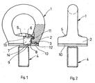
- connection eye of an attachment point designed as an eyebolt The connection eye 1 has a base 2, which is provided with a bore 3 for Recording an anchoring screw 4 is provided.
- the anchoring screw 4 has a head 5 which is provided with a hexagon socket 6.
- To the head 5 of the Anchoring screw 4 is followed by a first cylindrical portion 7, the via a narrow annular collar 8 in a second cylindrical section 9 passes. whose diameter is smaller than the diameter of the first cylindrical Section 7.
- an annular support disk 10 is pressed, which mounted in the Condition of the attachment point by the anchoring screw 4 against a contact surface is pressed.
- connection eye 1 To a high degree of rotational mobility of the connection eye 1 even with large at it To ensure attacking forces is the anchor point with two of deep groove ball bearings formed WälzSystem Researchn 11, 12, of which the WälzSystem Hor11 between an annular flange 13 of the head 5 of the anchoring screw 4 and the base 2 of the connection eye 1 and the row of rolling elements 12th between the underside of the base 2 of the connection eye 1 and the support plate 10th is arranged.
- the Kippfestmaschine the connection eye 1 it benefits that the diameter of the row of rolling elements 12 is greater than the diameter of the row of rolling elements 11.
- a devisnbohurung 14 in the support plate 10 forms an additional safeguard against axial displacements between the anchoring screw 4 and the Support disk 10.
Landscapes
- Engineering & Computer Science (AREA)
- Mechanical Engineering (AREA)
- General Engineering & Computer Science (AREA)
- Bolts, Nuts, And Washers (AREA)
- Hooks, Suction Cups, And Attachment By Adhesive Means (AREA)
- Diaphragms For Electromechanical Transducers (AREA)
- Pharmaceuticals Containing Other Organic And Inorganic Compounds (AREA)
- Saccharide Compounds (AREA)
- Tents Or Canopies (AREA)
Description
- Figur 1
- teilweise im Schnitt eine erste Ansicht eines als Ringschraube ausge bildeten Anschlagpunktes und
- Figur 2
- eine zweite Ansicht des Anschlagpunktes gemäß Figur 1.
Claims (5)
- Anschlagpunkt mit einer zum Einhängen eines Anschlag- oder Zurrmittels dienenden Anchlussöse und einer zu ihrer Befestigung an einem Gegenstand dienenden Verankerungsschraube, deren Kopf mit einem Ringflansch versehen ist, an dem sich die einem mit einer Bohrung versehenen Sockel aufweisende, drehbar auf der Verankerungsschraube gelagerte Anschlussöse abstützt, dadurch gekennzeichnet, dass mit der Verankerungsschraube (4) unverlierbar eine Stützscheibe (10) verbunden ist und dass der Sockel (2) der Anschlussöse (1) sich über eine erste Walzkörperreihe (11) gegen den Ringflansch (13) des Kopfes (5) und über eine zweite Walzkörperreihe (12) gegen die Stützscheibe (10) abstützt.
- Anschlagpunkt nach Anspruch 1, dadurch gekennzeichnet, dass sich an den Ringflansch (13) zwei zylindrische Abschnitte (7, 9) anschließen , von denen der dem Ringflansch (13) zugewandte Abschnitt (7) einen größeren Durchmesser hat als der dem Gewinde der Verankerungsschraube (4) zugewandte Abschnitt (9), und dass die Stützscheibe (10) mit einer Stufenbohrung (14) versehen ist, auf deren dem Kopf (5) der Verankerungsschraube (4) abgewandten Stufe sich die Stützscheibe (10) über einen die zylindrischen Abschnitte (7, 9) miteinander verbindenden Ringbund (8) abstützt.
- Anschlagpunkt nach Anspruch 1 oder 2, dadurch gekennzeichnet, dass die Verbindung zwischen der Verankerungsschraube (4) und der Stützscheibe (10) als Presspassverbindung ausgebildet ist
- Anschlagpunkt nach einem der Ansprüche 1 bis 3, dadurch gekennzeichnet, dass die Walzkörperreihen (11, 12) als Rillenkugellager ausgebildet sind.
- Anschlagpunkt nach einem der Ansprüche 1 bis 4, dadurch gekennzeichnet, dass der Durchmesser der ersten Wälzkörperreihe (11) kleiner ist als der Durchmesser der zweiten Wälzkörperreihe (12).
Applications Claiming Priority (3)
| Application Number | Priority Date | Filing Date | Title |
|---|---|---|---|
| DE10164593A DE10164593B4 (de) | 2001-12-21 | 2001-12-21 | Anschlagpunkt |
| DE10164593 | 2001-12-21 | ||
| PCT/DE2002/004690 WO2003056207A1 (de) | 2001-12-21 | 2002-12-18 | Anschlagpunkt |
Publications (2)
| Publication Number | Publication Date |
|---|---|
| EP1456560A1 EP1456560A1 (de) | 2004-09-15 |
| EP1456560B1 true EP1456560B1 (de) | 2005-10-05 |
Family
ID=7711220
Family Applications (1)
| Application Number | Title | Priority Date | Filing Date |
|---|---|---|---|
| EP02805734A Expired - Lifetime EP1456560B1 (de) | 2001-12-21 | 2002-12-18 | Anschlagpunkt |
Country Status (6)
| Country | Link |
|---|---|
| US (1) | US6994501B2 (de) |
| EP (1) | EP1456560B1 (de) |
| CN (1) | CN1295450C (de) |
| AT (1) | ATE306030T1 (de) |
| DE (2) | DE10164593B4 (de) |
| WO (1) | WO2003056207A1 (de) |
Cited By (1)
| Publication number | Priority date | Publication date | Assignee | Title |
|---|---|---|---|---|
| DE102013205723A1 (de) | 2013-03-28 | 2014-10-02 | Rud Ketten Rieger & Dietz Gmbh U. Co. Kg | Kugelgelagerter Anschlagpunkt |
Families Citing this family (16)
| Publication number | Priority date | Publication date | Assignee | Title |
|---|---|---|---|---|
| DE10164598B4 (de) * | 2001-12-21 | 2006-12-14 | Rud-Kettenfabrik Rieger & Dietz Gmbh U. Co. | Anschlussvorrichtung zum Anschließen von Anschlag- oder Verzurrmitteln |
| WO2008129860A1 (ja) * | 2007-04-17 | 2008-10-30 | Faltec Co., Ltd. | 車両用牽引装置と車両用牽引フックの製造方法並びに車両用連結部材の製造方法 |
| CN102878178A (zh) * | 2011-07-14 | 2013-01-16 | 鸿富锦精密工业(深圳)有限公司 | 螺丝结构 |
| US9127698B1 (en) | 2011-07-18 | 2015-09-08 | Richard Brull | Deck and patio anchoring device |
| DE202012100764U1 (de) * | 2012-03-05 | 2012-04-27 | Thiele Gmbh & Co. Kg | Ringschraube |
| EP2880334B1 (de) * | 2012-07-31 | 2016-06-08 | Pewag Austria GmbH | Ringmutter |
| US20150071732A1 (en) * | 2013-09-06 | 2015-03-12 | Yoke Industrial Corp. | Eyebolt |
| CN103982524B (zh) * | 2014-04-18 | 2015-12-02 | 丽水市飞天人机械设计有限公司 | 一种核电站用新型连接件 |
| DE102014208819A1 (de) | 2014-05-09 | 2015-11-12 | Rud Ketten Rieger & Dietz Gmbh U. Co. Kg | Ringelement mit einem geteilten Sockel für ein Zurr- oder Anschlagmittel |
| US10207902B2 (en) | 2016-09-01 | 2019-02-19 | Mjt Holdings, Llc | Load-mountable lift eye assembly |
| USD803668S1 (en) | 2016-09-01 | 2017-11-28 | Mjt Holdings, Llc | Load-mountable lifting eye |
| USD840794S1 (en) | 2017-11-27 | 2019-02-19 | Mjt Holdings, Llc | Load-mountable lift eye |
| US11097645B2 (en) * | 2018-05-24 | 2021-08-24 | Illinois Tool Works Inc. | Tie down assembly |
| USD922185S1 (en) * | 2020-11-17 | 2021-06-15 | Haoliang Liu | Bolt |
| USD974882S1 (en) * | 2021-05-17 | 2023-01-10 | Leon Griffin | Lifting eye |
| DE202022105768U1 (de) | 2022-10-12 | 2024-01-15 | J.D. Theile Gmbh & Co. Kg | Anschlagpunkt |
Family Cites Families (34)
| Publication number | Priority date | Publication date | Assignee | Title |
|---|---|---|---|---|
| DE138876C (de) * | ||||
| US1642958A (en) * | 1926-12-17 | 1927-09-20 | Leroy Mcdowell Moseley | Swivel hook |
| US1867574A (en) * | 1931-08-27 | 1932-07-19 | Nat Supply Co | Rod-line weight |
| US2544655A (en) * | 1945-08-03 | 1951-03-13 | Dwight A Chase | Swivel |
| US2651533A (en) * | 1948-08-10 | 1953-09-08 | Miller Cecil | Swivel |
| US2519460A (en) * | 1948-11-22 | 1950-08-22 | Young Iron Works | Butt-rigging swivel |
| DE876628C (de) | 1950-03-16 | 1953-05-15 | Elisabeth Heuer | Wirbel |
| US2672230A (en) * | 1951-06-09 | 1954-03-16 | Leonard A E Jetzke | Shielded swivel mount for conveyer hooks |
| US2748646A (en) * | 1952-09-13 | 1956-06-05 | Harold William | Separable eye for a bolt |
| US2812971A (en) * | 1954-06-01 | 1957-11-12 | John H Teutsch | Hoist lift connection for dies |
| US3297293A (en) * | 1965-01-13 | 1967-01-10 | American Drill Bushing Company | Fastening device |
| US3492033A (en) * | 1968-09-18 | 1970-01-27 | Charles R Mueller & Sons Inc | Clevis assembly |
| US3905633A (en) * | 1974-09-30 | 1975-09-16 | Caterpillar Tractor Co | Swivel mounted lifting eye for engines |
| US4295765A (en) * | 1979-04-23 | 1981-10-20 | Burke Michael R | Tie-down structure |
| US4431352A (en) * | 1981-09-28 | 1984-02-14 | Andrews Gary E | Fastening device |
| US4473984A (en) * | 1983-09-13 | 1984-10-02 | Lopez Donald A | Curtain-wall masonry-veneer anchor system |
| US4570987A (en) * | 1984-05-14 | 1986-02-18 | Hon Wong | Swivel eyebolt |
| DE8414736U1 (de) * | 1984-05-15 | 1984-08-16 | Pfeifer Seil- Und Hebetechnik Gmbh & Co, 8940 Memmingen | Ringschraube |
| US4641986A (en) * | 1985-08-30 | 1987-02-10 | Cbc Industries, Inc. | Multi-position eyebolt |
| US4705422A (en) * | 1986-08-08 | 1987-11-10 | Cbc Industries, Inc. | Multi-position fixture |
| US4699410A (en) * | 1986-08-28 | 1987-10-13 | Seidel Richard E | Swivel connector for hoists and the like |
| US4986712A (en) * | 1989-12-18 | 1991-01-22 | Emhart Industries, Inc. | Fastener assembly |
| US5125861A (en) * | 1990-08-20 | 1992-06-30 | Freeman Lewis G | Lifting eyebolt assembly |
| US5054982A (en) * | 1990-08-20 | 1991-10-08 | Freeman Lewis G | Lifting eyebolt assembly |
| US5183360A (en) * | 1990-08-20 | 1993-02-02 | Freeman Lewis G | Lifting eyebolt assembly |
| DE4403785A1 (de) * | 1993-10-25 | 1995-08-10 | Rud Ketten Rieger & Dietz | Ringschraube |
| DE4336780A1 (de) * | 1993-10-25 | 1995-04-27 | Rud Ketten Rieger & Dietz | Ringschraube |
| DE4336779C2 (de) * | 1993-10-25 | 1995-09-14 | Rud Ketten Rieger & Dietz | Anschlußvorrichtung |
| US5634734A (en) * | 1995-10-13 | 1997-06-03 | Jergens, Inc. | Hoist device |
| GB9725088D0 (en) * | 1997-11-25 | 1998-01-28 | Aston John A | Hoist ring assembly |
| US6022164A (en) * | 1998-01-20 | 2000-02-08 | Cbc Industries, Inc. | Captive multi-position fixture |
| US5992910A (en) * | 1998-07-01 | 1999-11-30 | Kwon; Soon Chil | Eyebolt assembly |
| US6398447B1 (en) * | 1998-07-01 | 2002-06-04 | Actek Manufacturing & Engineering Co. | Unitary eye bolt |
| DE10062971C1 (de) * | 2000-12-16 | 2002-08-22 | Theile J D Gmbh | Schäkel |
-
2001
- 2001-12-21 DE DE10164593A patent/DE10164593B4/de not_active Expired - Fee Related
-
2002
- 2002-12-18 EP EP02805734A patent/EP1456560B1/de not_active Expired - Lifetime
- 2002-12-18 CN CNB028258223A patent/CN1295450C/zh not_active Expired - Lifetime
- 2002-12-18 WO PCT/DE2002/004690 patent/WO2003056207A1/de not_active Ceased
- 2002-12-18 US US10/499,158 patent/US6994501B2/en not_active Expired - Lifetime
- 2002-12-18 DE DE50204495T patent/DE50204495D1/de not_active Expired - Lifetime
- 2002-12-18 AT AT02805734T patent/ATE306030T1/de active
Cited By (3)
| Publication number | Priority date | Publication date | Assignee | Title |
|---|---|---|---|---|
| DE102013205723A1 (de) | 2013-03-28 | 2014-10-02 | Rud Ketten Rieger & Dietz Gmbh U. Co. Kg | Kugelgelagerter Anschlagpunkt |
| WO2014154739A1 (de) | 2013-03-28 | 2014-10-02 | Rud Ketten Rieger & Dietz Gmbh U. Co. Kg | Kugelgelagerter anschlagpunkt |
| US9816550B2 (en) | 2013-03-28 | 2017-11-14 | Rud Ketten Rieger & Dietz GmbH U CO. K.G. | Ball-bearing-supported attachment point |
Also Published As
| Publication number | Publication date |
|---|---|
| DE10164593B4 (de) | 2006-01-12 |
| DE10164593A1 (de) | 2003-07-10 |
| WO2003056207A1 (de) | 2003-07-10 |
| CN1295450C (zh) | 2007-01-17 |
| ATE306030T1 (de) | 2005-10-15 |
| EP1456560A1 (de) | 2004-09-15 |
| US20050019135A1 (en) | 2005-01-27 |
| DE50204495D1 (de) | 2006-02-16 |
| CN1606666A (zh) | 2005-04-13 |
| US6994501B2 (en) | 2006-02-07 |
Similar Documents
| Publication | Publication Date | Title |
|---|---|---|
| EP1456560B1 (de) | Anschlagpunkt | |
| DE69003574T2 (de) | Höheneinstellvorrichtung, insbesondere für Möbel. | |
| DE102021207060A1 (de) | Einstellbarer Nivellierbausatz und zugehöriges Montageverfahren | |
| WO2008000668A1 (de) | Scheibe und damit versehene schraubenverbindung | |
| EP2241527B1 (de) | Anschlussvorrichtung | |
| EP2844601B1 (de) | Ringschraube mit gleitscheibe | |
| DE102013205723A1 (de) | Kugelgelagerter Anschlagpunkt | |
| DE102009017718A1 (de) | Lastaufnahmemittel, insbesondere eine Unterflasche eines Hebezeuges | |
| DE102004007758A1 (de) | Lagervorrichtung zur Lagerung eines hochtourig laufenden Rotors | |
| EP3175066A1 (de) | Rolle | |
| EP1456559B1 (de) | Anschlagmittel | |
| EP4353666B1 (de) | Anschlagpunkt | |
| EP3909903A1 (de) | Anschlagpunkt | |
| DE20021334U1 (de) | Anschlagring | |
| DE202019100823U1 (de) | Wirbelringschraube | |
| DE20121123U1 (de) | Anschlagpunkt | |
| DE10236408A1 (de) | Aufhängung eines Lasthakens, insbesondere für Unterflaschen von Hebezeugen | |
| DE102006019982A1 (de) | Wälzlager-Drehverbindung | |
| EP4136048B1 (de) | Anschlagpunkt | |
| DE102022110654B3 (de) | Dreh- und schwenkbare Ringschraube | |
| DE202019106511U1 (de) | Einfach montierbarer Knarrenschlüssel | |
| DE65405C (de) | ||
| DE202005019358U1 (de) | Anschlagwirbel | |
| DE20001153U1 (de) | Ringmutter | |
| DE102012014256B4 (de) | Aufhängung eines Feststranges bei einemmehrsträngig ausgeführten Hebezeug |
Legal Events
| Date | Code | Title | Description |
|---|---|---|---|
| PUAI | Public reference made under article 153(3) epc to a published international application that has entered the european phase |
Free format text: ORIGINAL CODE: 0009012 |
|
| 17P | Request for examination filed |
Effective date: 20040616 |
|
| AK | Designated contracting states |
Kind code of ref document: A1 Designated state(s): AT BE BG CH CY CZ DE DK EE ES FI FR GB GR IE IT LI LU MC NL PT SE SI SK TR |
|
| GRAP | Despatch of communication of intention to grant a patent |
Free format text: ORIGINAL CODE: EPIDOSNIGR1 |
|
| GRAS | Grant fee paid |
Free format text: ORIGINAL CODE: EPIDOSNIGR3 |
|
| GRAA | (expected) grant |
Free format text: ORIGINAL CODE: 0009210 |
|
| AK | Designated contracting states |
Kind code of ref document: B1 Designated state(s): AT BE BG CH CY CZ DE DK EE ES FI FR GB GR IE IT LI LU MC NL PT SE SI SK TR |
|
| PG25 | Lapsed in a contracting state [announced via postgrant information from national office to epo] |
Ref country code: EE Free format text: LAPSE BECAUSE OF FAILURE TO SUBMIT A TRANSLATION OF THE DESCRIPTION OR TO PAY THE FEE WITHIN THE PRESCRIBED TIME-LIMIT Effective date: 20051005 Ref country code: SK Free format text: LAPSE BECAUSE OF FAILURE TO SUBMIT A TRANSLATION OF THE DESCRIPTION OR TO PAY THE FEE WITHIN THE PRESCRIBED TIME-LIMIT Effective date: 20051005 Ref country code: IE Free format text: LAPSE BECAUSE OF FAILURE TO SUBMIT A TRANSLATION OF THE DESCRIPTION OR TO PAY THE FEE WITHIN THE PRESCRIBED TIME-LIMIT Effective date: 20051005 Ref country code: SI Free format text: LAPSE BECAUSE OF FAILURE TO SUBMIT A TRANSLATION OF THE DESCRIPTION OR TO PAY THE FEE WITHIN THE PRESCRIBED TIME-LIMIT Effective date: 20051005 Ref country code: FI Free format text: LAPSE BECAUSE OF FAILURE TO SUBMIT A TRANSLATION OF THE DESCRIPTION OR TO PAY THE FEE WITHIN THE PRESCRIBED TIME-LIMIT Effective date: 20051005 Ref country code: NL Free format text: LAPSE BECAUSE OF FAILURE TO SUBMIT A TRANSLATION OF THE DESCRIPTION OR TO PAY THE FEE WITHIN THE PRESCRIBED TIME-LIMIT Effective date: 20051005 Ref country code: TR Free format text: LAPSE BECAUSE OF FAILURE TO SUBMIT A TRANSLATION OF THE DESCRIPTION OR TO PAY THE FEE WITHIN THE PRESCRIBED TIME-LIMIT Effective date: 20051005 |
|
| REG | Reference to a national code |
Ref country code: GB Ref legal event code: FG4D Free format text: NOT ENGLISH |
|
| REG | Reference to a national code |
Ref country code: CH Ref legal event code: EP |
|
| REG | Reference to a national code |
Ref country code: IE Ref legal event code: FG4D Free format text: LANGUAGE OF EP DOCUMENT: GERMAN |
|
| PG25 | Lapsed in a contracting state [announced via postgrant information from national office to epo] |
Ref country code: CY Free format text: LAPSE BECAUSE OF FAILURE TO SUBMIT A TRANSLATION OF THE DESCRIPTION OR TO PAY THE FEE WITHIN THE PRESCRIBED TIME-LIMIT Effective date: 20051218 |
|
| REG | Reference to a national code |
Ref country code: SE Ref legal event code: TRGR |
|
| PG25 | Lapsed in a contracting state [announced via postgrant information from national office to epo] |
Ref country code: MC Free format text: LAPSE BECAUSE OF NON-PAYMENT OF DUE FEES Effective date: 20051231 Ref country code: BE Free format text: LAPSE BECAUSE OF NON-PAYMENT OF DUE FEES Effective date: 20051231 Ref country code: LU Free format text: LAPSE BECAUSE OF NON-PAYMENT OF DUE FEES Effective date: 20051231 |
|
| PG25 | Lapsed in a contracting state [announced via postgrant information from national office to epo] |
Ref country code: BG Free format text: LAPSE BECAUSE OF FAILURE TO SUBMIT A TRANSLATION OF THE DESCRIPTION OR TO PAY THE FEE WITHIN THE PRESCRIBED TIME-LIMIT Effective date: 20060105 Ref country code: GR Free format text: LAPSE BECAUSE OF FAILURE TO SUBMIT A TRANSLATION OF THE DESCRIPTION OR TO PAY THE FEE WITHIN THE PRESCRIBED TIME-LIMIT Effective date: 20060105 Ref country code: DK Free format text: LAPSE BECAUSE OF FAILURE TO SUBMIT A TRANSLATION OF THE DESCRIPTION OR TO PAY THE FEE WITHIN THE PRESCRIBED TIME-LIMIT Effective date: 20060105 |
|
| GBT | Gb: translation of ep patent filed (gb section 77(6)(a)/1977) |
Effective date: 20051220 |
|
| PG25 | Lapsed in a contracting state [announced via postgrant information from national office to epo] |
Ref country code: ES Free format text: LAPSE BECAUSE OF FAILURE TO SUBMIT A TRANSLATION OF THE DESCRIPTION OR TO PAY THE FEE WITHIN THE PRESCRIBED TIME-LIMIT Effective date: 20060116 |
|
| REF | Corresponds to: |
Ref document number: 50204495 Country of ref document: DE Date of ref document: 20060216 Kind code of ref document: P |
|
| NLV1 | Nl: lapsed or annulled due to failure to fulfill the requirements of art. 29p and 29m of the patents act | ||
| PG25 | Lapsed in a contracting state [announced via postgrant information from national office to epo] |
Ref country code: PT Free format text: LAPSE BECAUSE OF FAILURE TO SUBMIT A TRANSLATION OF THE DESCRIPTION OR TO PAY THE FEE WITHIN THE PRESCRIBED TIME-LIMIT Effective date: 20060306 |
|
| REG | Reference to a national code |
Ref country code: IE Ref legal event code: FD4D |
|
| ET | Fr: translation filed | ||
| PLBE | No opposition filed within time limit |
Free format text: ORIGINAL CODE: 0009261 |
|
| STAA | Information on the status of an ep patent application or granted ep patent |
Free format text: STATUS: NO OPPOSITION FILED WITHIN TIME LIMIT |
|
| 26N | No opposition filed |
Effective date: 20060706 |
|
| PG25 | Lapsed in a contracting state [announced via postgrant information from national office to epo] |
Ref country code: CH Free format text: LAPSE BECAUSE OF NON-PAYMENT OF DUE FEES Effective date: 20061231 Ref country code: LI Free format text: LAPSE BECAUSE OF NON-PAYMENT OF DUE FEES Effective date: 20061231 |
|
| REG | Reference to a national code |
Ref country code: CH Ref legal event code: PL |
|
| BERE | Be: lapsed |
Owner name: RUD-KETTENFABRIK RIEGER & DIETZ G.M.B.H. U. CO. Effective date: 20051231 |
|
| REG | Reference to a national code |
Ref country code: FR Ref legal event code: CD |
|
| REG | Reference to a national code |
Ref country code: FR Ref legal event code: CA Effective date: 20131001 |
|
| REG | Reference to a national code |
Ref country code: FR Ref legal event code: RM Effective date: 20131126 |
|
| REG | Reference to a national code |
Ref country code: FR Ref legal event code: PLFP Year of fee payment: 14 |
|
| PGFP | Annual fee paid to national office [announced via postgrant information from national office to epo] |
Ref country code: CZ Payment date: 20151130 Year of fee payment: 14 |
|
| REG | Reference to a national code |
Ref country code: FR Ref legal event code: PLFP Year of fee payment: 15 |
|
| PG25 | Lapsed in a contracting state [announced via postgrant information from national office to epo] |
Ref country code: CZ Free format text: LAPSE BECAUSE OF NON-PAYMENT OF DUE FEES Effective date: 20161218 |
|
| REG | Reference to a national code |
Ref country code: FR Ref legal event code: PLFP Year of fee payment: 16 |
|
| PGFP | Annual fee paid to national office [announced via postgrant information from national office to epo] |
Ref country code: GB Payment date: 20211217 Year of fee payment: 20 Ref country code: FR Payment date: 20211217 Year of fee payment: 20 Ref country code: SE Payment date: 20211218 Year of fee payment: 20 Ref country code: AT Payment date: 20211221 Year of fee payment: 20 |
|
| PGFP | Annual fee paid to national office [announced via postgrant information from national office to epo] |
Ref country code: DE Payment date: 20211222 Year of fee payment: 20 |
|
| PGFP | Annual fee paid to national office [announced via postgrant information from national office to epo] |
Ref country code: IT Payment date: 20211231 Year of fee payment: 20 |
|
| REG | Reference to a national code |
Ref country code: DE Ref legal event code: R071 Ref document number: 50204495 Country of ref document: DE |
|
| REG | Reference to a national code |
Ref country code: GB Ref legal event code: PE20 Expiry date: 20221217 |
|
| PG25 | Lapsed in a contracting state [announced via postgrant information from national office to epo] |
Ref country code: GB Free format text: LAPSE BECAUSE OF EXPIRATION OF PROTECTION Effective date: 20221217 |
|
| REG | Reference to a national code |
Ref country code: SE Ref legal event code: EUG |
|
| REG | Reference to a national code |
Ref country code: AT Ref legal event code: MK07 Ref document number: 306030 Country of ref document: AT Kind code of ref document: T Effective date: 20221218 |