EP1456570B1 - Soupape dotee d'un element d'amortissement - Google Patents
Soupape dotee d'un element d'amortissement Download PDFInfo
- Publication number
- EP1456570B1 EP1456570B1 EP02794981A EP02794981A EP1456570B1 EP 1456570 B1 EP1456570 B1 EP 1456570B1 EP 02794981 A EP02794981 A EP 02794981A EP 02794981 A EP02794981 A EP 02794981A EP 1456570 B1 EP1456570 B1 EP 1456570B1
- Authority
- EP
- European Patent Office
- Prior art keywords
- valve
- stroke rod
- damping element
- valve according
- lifting rod
- Prior art date
- Legal status (The legal status is an assumption and is not a legal conclusion. Google has not performed a legal analysis and makes no representation as to the accuracy of the status listed.)
- Expired - Lifetime
Links
- 238000013016 damping Methods 0.000 title claims description 43
- 238000001816 cooling Methods 0.000 claims description 8
- 238000010438 heat treatment Methods 0.000 claims description 8
- 239000007788 liquid Substances 0.000 claims description 6
- 230000000750 progressive effect Effects 0.000 claims description 4
- 230000001105 regulatory effect Effects 0.000 claims 1
- 239000012530 fluid Substances 0.000 description 4
- 239000000463 material Substances 0.000 description 4
- 230000008901 benefit Effects 0.000 description 3
- 238000006073 displacement reaction Methods 0.000 description 3
- 230000000694 effects Effects 0.000 description 3
- 239000013013 elastic material Substances 0.000 description 3
- 230000001404 mediated effect Effects 0.000 description 3
- 230000009467 reduction Effects 0.000 description 3
- 238000007789 sealing Methods 0.000 description 3
- 238000009434 installation Methods 0.000 description 2
- 238000004519 manufacturing process Methods 0.000 description 2
- 238000000034 method Methods 0.000 description 2
- XLYOFNOQVPJJNP-UHFFFAOYSA-N water Substances O XLYOFNOQVPJJNP-UHFFFAOYSA-N 0.000 description 2
- 230000004913 activation Effects 0.000 description 1
- 239000012190 activator Substances 0.000 description 1
- 238000004378 air conditioning Methods 0.000 description 1
- 230000015572 biosynthetic process Effects 0.000 description 1
- 238000002485 combustion reaction Methods 0.000 description 1
- 230000001934 delay Effects 0.000 description 1
- 239000000446 fuel Substances 0.000 description 1
- 230000008569 process Effects 0.000 description 1
Images


Classifications
-
- F—MECHANICAL ENGINEERING; LIGHTING; HEATING; WEAPONS; BLASTING
- F16—ENGINEERING ELEMENTS AND UNITS; GENERAL MEASURES FOR PRODUCING AND MAINTAINING EFFECTIVE FUNCTIONING OF MACHINES OR INSTALLATIONS; THERMAL INSULATION IN GENERAL
- F16K—VALVES; TAPS; COCKS; ACTUATING-FLOATS; DEVICES FOR VENTING OR AERATING
- F16K31/00—Actuating devices; Operating means; Releasing devices
- F16K31/02—Actuating devices; Operating means; Releasing devices electric; magnetic
- F16K31/06—Actuating devices; Operating means; Releasing devices electric; magnetic using a magnet, e.g. diaphragm valves, cutting off by means of a liquid
- F16K31/0686—Braking, pressure equilibration, shock absorbing
- F16K31/0696—Shock absorbing, e.g. using a dash-pot
-
- F—MECHANICAL ENGINEERING; LIGHTING; HEATING; WEAPONS; BLASTING
- F01—MACHINES OR ENGINES IN GENERAL; ENGINE PLANTS IN GENERAL; STEAM ENGINES
- F01P—COOLING OF MACHINES OR ENGINES IN GENERAL; COOLING OF INTERNAL-COMBUSTION ENGINES
- F01P7/00—Controlling of coolant flow
- F01P7/14—Controlling of coolant flow the coolant being liquid
-
- F—MECHANICAL ENGINEERING; LIGHTING; HEATING; WEAPONS; BLASTING
- F16—ENGINEERING ELEMENTS AND UNITS; GENERAL MEASURES FOR PRODUCING AND MAINTAINING EFFECTIVE FUNCTIONING OF MACHINES OR INSTALLATIONS; THERMAL INSULATION IN GENERAL
- F16K—VALVES; TAPS; COCKS; ACTUATING-FLOATS; DEVICES FOR VENTING OR AERATING
- F16K31/00—Actuating devices; Operating means; Releasing devices
- F16K31/02—Actuating devices; Operating means; Releasing devices electric; magnetic
- F16K31/06—Actuating devices; Operating means; Releasing devices electric; magnetic using a magnet, e.g. diaphragm valves, cutting off by means of a liquid
- F16K31/0686—Braking, pressure equilibration, shock absorbing
- F16K31/0689—Braking of the valve element
-
- F—MECHANICAL ENGINEERING; LIGHTING; HEATING; WEAPONS; BLASTING
- F16—ENGINEERING ELEMENTS AND UNITS; GENERAL MEASURES FOR PRODUCING AND MAINTAINING EFFECTIVE FUNCTIONING OF MACHINES OR INSTALLATIONS; THERMAL INSULATION IN GENERAL
- F16K—VALVES; TAPS; COCKS; ACTUATING-FLOATS; DEVICES FOR VENTING OR AERATING
- F16K47/00—Means in valves for absorbing fluid energy
- F16K47/01—Damping of valve members
-
- F—MECHANICAL ENGINEERING; LIGHTING; HEATING; WEAPONS; BLASTING
- F01—MACHINES OR ENGINES IN GENERAL; ENGINE PLANTS IN GENERAL; STEAM ENGINES
- F01P—COOLING OF MACHINES OR ENGINES IN GENERAL; COOLING OF INTERNAL-COMBUSTION ENGINES
- F01P7/00—Controlling of coolant flow
- F01P7/14—Controlling of coolant flow the coolant being liquid
- F01P2007/146—Controlling of coolant flow the coolant being liquid using valves
Definitions
- the invention is based on a valve according to the preamble of the independent claim.
- valves are known for example from liquid-controlled heating or cooling systems of motor vehicles.
- a valve member mounted on a lift rod of the valve regulates the flow between an inlet channel and at least one outlet channel.
- the valve can be controlled, for example, as a function of temperatures in the heating and / or air conditioning of the motor vehicle or the passenger compartment.
- valves of this type mainly still have an electromagnetic actuator which closes the valve by means of an energized magnetic coil in that the actuator acts on an armature connected to the lifting rod of the valve.
- the actuation of the actuator leads to an abrupt closing and thus pressure disturbances in the liquid system of the cooling circuit.
- a solenoid valve for a liquid-controlled heating and / or cooling system which has an inlet channel and at least one outlet channel whose mutual connection is made by an electromagnetically switched valve member in a first switching position and locked in a second switching position .
- the valve of DE 197 54 257 A1 has on its valve stem an elastic element in the form of a spring, which delays the speed of the valve stem when closing the valve member.
- the spring element between the valve member and the valve stem is arranged.
- a damping disk is additionally fixedly arranged on the valve stem and moves in a damping chamber filled with a viscous fluid.
- a plurality of throttle bores are provided in the damping disk, which determine the resistance of the damping disc against the viscous liquid and thus delay the movement of the lifting rod in the desired manner.
- a safety valve which has a two-part lifting rod. While the first part of the lifting rod is connected to an actuator for the valve, the second part of the lifting rod carries two spaced-apart valve members.
- the two parts of the lifting rod of US 4,364,541 are mutually displaceable in the axial direction of the lifting rod.
- the relative mobility of the two Hubstangenmaschine each other is mediated by an elastic spring element.
- a disadvantage of the safety valve described in US Pat. No. 4,364,541 is the complicated mutual decoupling of the two lifting rod components.
- the relative mobility of the two Hubstangenanteile must be adjusted in this prior art by an additional spring element.
- Such a valve requires, as well as the valve of DE 197 54 257 A1, a complex assembly, not least due to the large number of items.
- the complex design of the moving parts of the valve leads to increased demands on the actuator, which in turn go hand in hand with an increased weight and a large installation volume of the valve unit.
- a control valve for steam, in particular fuel vapor of an internal combustion engine is known.
- This clocked valve has a lifting rod and a valve member mounted on the lifting rod, which cooperates with a valve seat of a valve chamber.
- the valve member has, on its side facing the valve seat, a conically shaped ring made of a flexible material, which lays on the border of the valve seat when the valve closes.
- the size and shape of this conical ring, which is formed on the valve member of the valve of US-A-5 579 741, is chosen such that the ring receives its necessary shape when closing the valve, but leads to a noise reduction during closing due to a damping effect ,
- valve according to the invention with the features of the main claim has the advantage that a simple and quick installation in the manufacture of generic valves is possible.
- the valve weight can also be significantly reduced.
- the damping element simultaneously assumes the sealing function on the valve seat of the valve. In this way, a large number of components is saved in the assembly of the valve, whose complexity and probability of failure is also reduced.
- the surface contour of the movement limiter for the damping element on a spoke-like, emanating from the central lifting rod basic structure is immersing the contour in the elastic damping element results in a steady increase in the bearing surface of the damping element on the mechanical stop of the damper ring, resulting in a progressive deceleration of the lifting rod.
- valve according to the invention for example in the embodiment of an electromagnetic clock valve for the cooling and / or heating circuit of a motor vehicle is possible with advantages over the corresponding valves of the prior art.
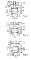
- the valve member 20 is mounted axially displaceably on a lifting rod 26 and is secured to the, the valve seat 24 facing the end of the lifting rod 26 by a locking plate 28 on the lifting rod 26.
- a damper ring 30 On the side facing away from the valve seat 24 of the valve member 20 is a damper ring 30 in the form of a mechanical stop plate 32 which is fixedly connected to the lifting rod 26 and limiter limits the axial mobility of the valve member 20 along the lifting rod 26.
- armature 34 On the lifting rod 26 also a scraper ring 33 and an armature 34 is fixed, which cooperates with a magnetic coil 36 and forms the electromagnetic actuator 60 for the valve according to the invention in the embodiment of Figure 1.
- the armature 34 is guided in an armature space 38 of the actuator 60 by a guide bush 40 axially displaceable.
- FIG. 2 shows a detailed view of a valve 1 10 according to the invention in the region of its valve chamber 218.
- An inlet channel 214 and an outlet channel 216 lead into the valve chamber 218, which in this exemplary embodiment is formed by a one-piece valve chamber unit 221.
- the connection between the inlet channel 214 and the outlet channel 216 is mediated by a valve member 220 which cooperates with a valve seat 224 of the valve chamber 218.
- the valve seat 242 is integrally formed with the valve housing 248.
- Other embodiments of the valve seat of a valve 10 according to the invention are of course also possible.
- the valve member 220 is actuated via a lifting rod 226 by an actuator, not shown, which does not necessarily have to be a magnetic activator.
- an actuator not shown, which does not necessarily have to be a magnetic activator.
- On the lifting rod 226 is also located in the region of the valve member 220, a locking plate 228, which limits the axial movement of the valve member 220 on the lifting rod 226 on one side.
- the elastic valve ring 250 may be integrally formed with the valve cone 222 and, for example, also consist of the same elastic sealing rubber material as the valve cone 222.
- valve member 220 On the valve seat 224 facing side of the lifting rod 226, the valve member 220 is countered by means of the securing plate 228 on the lifting rod.
- the valve member 220 on the stop plate 228, which has a larger diameter than the lifting rod 226 in the embodiment, are slipped.
- the stop plate 228 may be integrally formed with the lifting rod 226 or else fixed by common connection method to the lifting rod.
- a stop plate 232 serving as a limiter is fixed on the lifting rod 226 such that relative movement of the valve member 220 between the securing plate 228 and this stop plate 232 is possible.
- the stop plate 232 may be both integral with the lifting rod, as well as in other, well-known to those skilled species, be firmly connected to the lifting rod.
- the stop plate 232 On its underside 252 facing the valve member 220, as can be seen in particular in FIG. 6, the stop plate 232 has a spoke-shaped surface structure 254 which protrudes from the surface 256 of the underside 252 of the stop plate.
- FIG. 2 A perspective detail view of the stop plate 232, for clarity and clarity with the valve member removed, is shown in FIG.
- the stop plate 232 mounted on the lifting rod 226 has three spoke-shaped from the lifting rod 226 radially outwardly facing elevations 258, which in the direction of the valve member 220, or in the direction of the fuse plate 228, pointed and over in their height the surface 256 of the bottom 252 of the stop plate 232, starting from the lifting rod 226, radially to the outside.
- valve member 220 is spaced from the bottom 252 of the stop plate 232 on the lifting rod. If the valve is closed by actuation of its actuator, the valve cone 222 first settles on the valve seat 224 through the intermediary of the lifting rod 226, as is also shown in FIG. The further closing movement of the lifting rod 226 then leads to a relative movement of the lifting rod 226 with its attached stop plate 232 against the valve member 220. In this case, the surface contour 254 dives on the bottom 252 of the stop plate 232 in the elastic material of the valve member 220 a. The downward movement of the lifting rod 226 is thereby braked and a possible noise during the closing of the valve significantly reduced.
- the surface contour 254 on the underside 252 of the stop plate 232 is characterized in the embodiment shown in Figure 6 by a continuous increase of the cross section against the working direction of the lifting rod 226.
- the surface contour 254 of the stop plate 232 in the elastic material of the valve ring 250 therefore results in a progressive damping characteristic.
- the damping behavior of the valve according to the invention and thus also its noise during operation of the valve can be positively influenced.
- This can be done in an advantageous manner without changing the material properties of the actual valve cone 222.
- the valve ring 250 another Material than the poppet 222 have. It is also possible to separate the valve ring 250 from the valve plug 222, and to make the valve member 220 in multiple pieces, so that an additional relative movement between these two elements of the valve member 220 is possible.
- the underside 252 of the stop plate 232 lies almost flat on the surface of the valve ring 250.
- valve according to the invention is not limited to the embodiments shown in Figures 1 to 6.
- valve according to the invention is not limited to an embodiment as an electromagnetically activated timing valve. Hydraulic or pneumatic actuators are also possible, for example, in addition to other embodiments for the valve according to the invention.
- valve according to the invention is not limited to the presence of only one valve member with associated stop plate, but can be used in an advantageous manner for valves with, for example, two outlet channels with correspondingly associated two valve seats.
- an embodiment of the valve according to the invention with two valve members may be provided with the respective associated stop plates.
- valve according to the invention is not limited to the flow direction of the fluid to be controlled, which is illustrated in the exemplary embodiment of FIG.
- the valve according to the invention is in particular not limited to the shape of the surface contour of the stop plate for the valve member shown in the exemplary embodiments.
- this surface contour is not limited in its shape to the embodiment shown in FIG.
- tapered or pointed to the valve member tapered surface structures can be realized depending on the desired damping behavior as well for the valve according to the invention.
- valve according to the invention is also not limited to an application in liquid-controlled heating and / or cooling systems for motor vehicles.
Landscapes
- Engineering & Computer Science (AREA)
- General Engineering & Computer Science (AREA)
- Mechanical Engineering (AREA)
- Chemical & Material Sciences (AREA)
- Combustion & Propulsion (AREA)
- Magnetically Actuated Valves (AREA)
- Details Of Valves (AREA)
- Lift Valve (AREA)
Claims (13)
- Soupape, notamment pour une installation de chauffage et/ou de refroidissement à fluide, régulée, d'un véhicule automobile, comportant une chambre (18, 218) reliée à au moins un canal d'entrée (14, 214) et à au moins un canal de sortie (16, 216) ainsi qu'une tige de translation (26, 226) commandée par un actionneur, au moins un organe de soupape (20, 220) porté par la tige de translation (26, 226), et coopérant avec au moins un siège de soupape (24, 224) de la chambre (18, 218), et au moins un élément amortisseur (20, 220) prévu pour réduire la vitesse de la tige de translation (26, 226) lors de la fermeture de la soupape (10, 12) et servir en même temps d'organe d'obturation (20, 220),
caractérisée en ce qu'
au moins un élément amortisseur (20, 220) est coulissant axialement par rapport à la tige de translation (26, 226), notamment sur la tige de translation (26, 226). - Soupape selon la revendication 1,
caractérisée en ce que
l'élément amortisseur (20, 220) est un organe au moins en partie élastique installé sur la tige de translation (26, 226). - Soupape selon la revendication 1,
caractérisée en ce que
la tige de translation (26, 226) comporte des moyens (28, 30, 32, 228, 232) limitant la mobilité de l'élément amortisseur (20, 220) par rapport à la tige de translation (26, 226). - Soupape selon la revendication 3,
caractérisée en ce que
les moyens (28, 30, 32, 228, 232) sont réalisés sous la forme d'une butée mécanique. - Soupape selon la revendication 4,
caractérisée en ce qu'
au moins une butée mécanique (30, 32, 232) comporte sur son côté (252) tourné vers l'élément amortisseur (20, 220), un contour de surface (254) dirigé vers l'élément amortisseur (20, 220) et qui lors de la fermeture de la soupape (10, 12) pénètre successivement dans l'élément amortisseur (20, 220). - Soupape selon la revendication 5,
caractérisée en ce que
le contour de surface (254) d'au moins une butée mécanique (30, 32, 232) de l'élément amortisseur (20, 220) est réalisé de façon à avoir une courbe caractéristique d'amortissement progressif pour la tige de translation (26, 226) de la soupape (10, 12). - Soupape selon la revendication 5 ou 6,
caractérisée en ce que
le contour de surface (252) de la butée mécanique (32, 232) a une forme rayonnante avec une structure de base dirigée radialement vers l'extérieur à partir de la tige de translation. - Soupape selon l'une des revendications 5 à 7,
caractérisée en ce que
le contour de surface (2524) de la butée mécanique (30, 32, 232) se termine en pointe en direction de l'élément amortisseur (20, 220). - Soupape selon l'une des revendications 3 à 8,
caractérisée en ce que
les moyens (28, 30, 32, 228, 232) sont réalisés en une seule pièce avec la tige de translation (26, 226). - Soupape selon l'une des revendications précédentes,
caractérisée en ce que
la tige de translation (26, 226) est fabriquée principalement en matière plastique. - Soupape selon la revendication 10,
caractérisée en ce qu'
au moins un organe de soupape (20, 220) est pressé de force directement sur la tige de translation (26, 226). - Soupape selon l'une des revendications précédentes,
caractérisée en ce que
la soupape (10, 12) comporte un actionneur électromagnétique (60). - Soupape selon l'une des revendications précédentes,
caractérisée en ce qu'
un second canal de sortie muni d'un siège de soupape et d'un organe de soupape est issu de la chambre de soupape (18, 218) de la soupape (10, 12).
Applications Claiming Priority (3)
| Application Number | Priority Date | Filing Date | Title |
|---|---|---|---|
| DE10160970 | 2001-12-11 | ||
| DE10160970A DE10160970A1 (de) | 2001-12-11 | 2001-12-11 | Ventil mit Dämfungselement |
| PCT/DE2002/004502 WO2003054428A1 (fr) | 2001-12-11 | 2002-12-10 | Soupape dotee d'un element d'amortissement |
Publications (2)
| Publication Number | Publication Date |
|---|---|
| EP1456570A1 EP1456570A1 (fr) | 2004-09-15 |
| EP1456570B1 true EP1456570B1 (fr) | 2006-10-04 |
Family
ID=7708900
Family Applications (1)
| Application Number | Title | Priority Date | Filing Date |
|---|---|---|---|
| EP02794981A Expired - Lifetime EP1456570B1 (fr) | 2001-12-11 | 2002-12-10 | Soupape dotee d'un element d'amortissement |
Country Status (5)
| Country | Link |
|---|---|
| US (1) | US6951330B2 (fr) |
| EP (1) | EP1456570B1 (fr) |
| KR (1) | KR20040070213A (fr) |
| DE (2) | DE10160970A1 (fr) |
| WO (1) | WO2003054428A1 (fr) |
Families Citing this family (10)
| Publication number | Priority date | Publication date | Assignee | Title |
|---|---|---|---|---|
| DE102004030976A1 (de) * | 2004-06-26 | 2006-01-19 | Robert Bosch Gmbh | Taktventil |
| WO2007092778A2 (fr) * | 2006-02-03 | 2007-08-16 | Stoneridge, Inc. | Valve solenoide |
| US20070227512A1 (en) * | 2006-02-03 | 2007-10-04 | Stoneridge, Inc. | Solenoid Valve |
| WO2010106361A1 (fr) * | 2009-03-16 | 2010-09-23 | Artemis Intelligent Power Limited | Soupapes contrôlées électroniquement |
| DE102009046822A1 (de) * | 2009-11-18 | 2011-05-19 | Robert Bosch Gmbh | Schaltventil mit einem in einem Gehäuse bewegbaren Ventilelement |
| DE102011090006B4 (de) * | 2011-12-28 | 2015-03-26 | Continental Automotive Gmbh | Ventil |
| DE102012214920A1 (de) * | 2012-08-22 | 2014-02-27 | Continental Automotive Gmbh | Dämpfungsoberfläche an Ventilkomponenten |
| DE102013225392A1 (de) * | 2013-12-10 | 2015-06-11 | Robert Bosch Gmbh | Elektromagnet eines elektromagnetisch betätigten Fluidventils |
| US10302223B2 (en) | 2015-12-21 | 2019-05-28 | Baker Hughes, A Ge Company, Llc | Anti-chattering valve cone and methods for using same |
| DE102016201474B4 (de) * | 2016-02-01 | 2026-03-05 | Robert Bosch Gmbh | Ventilanker für ein Magnetventil und Ventilpatrone für ein Magnetventil |
Family Cites Families (8)
| Publication number | Priority date | Publication date | Assignee | Title |
|---|---|---|---|---|
| FR2479942A1 (fr) | 1980-04-02 | 1981-10-09 | Electricite De France | Dispositif d'isolement a soupape de surete taree |
| DE3431037A1 (de) * | 1984-08-23 | 1986-03-06 | Leybold-Heraeus GmbH, 5000 Köln | Magnetventil fuer die vakuumanwendung |
| DE9014763U1 (de) | 1990-10-25 | 1991-01-10 | Schultz, Wolfgang E., Dipl.-Ing., 8940 Memmingen | Elektromagnet |
| US5579741A (en) * | 1995-11-30 | 1996-12-03 | Siemens Electric Limited | Vapor purge valve having tapered bead armature seal |
| FR2745058B1 (fr) * | 1996-02-15 | 1999-02-26 | Eaton Sa Monaco | Electrovanne de regulation pour circuit de fluide, notamment gazeux |
| DE19707666C2 (de) * | 1997-02-26 | 1999-12-02 | Ford Global Tech Inc | Elektromagnetventil, insbesondere für Heizungsanlagen in Kraftfahrzeugen |
| DE19754257A1 (de) | 1997-12-06 | 1999-06-10 | Bosch Gmbh Robert | Magnetventil für eine flüssigkeitsgeregelte Heiz- und/oder Kühlanlage |
| DE10017030B4 (de) * | 2000-03-31 | 2005-05-19 | Rausch & Pausch Gmbh | Magnetventil |
-
2001
- 2001-12-11 DE DE10160970A patent/DE10160970A1/de not_active Withdrawn
-
2002
- 2002-12-10 DE DE50208363T patent/DE50208363D1/de not_active Expired - Lifetime
- 2002-12-10 US US10/467,132 patent/US6951330B2/en not_active Expired - Fee Related
- 2002-12-10 WO PCT/DE2002/004502 patent/WO2003054428A1/fr not_active Ceased
- 2002-12-10 KR KR10-2004-7008897A patent/KR20040070213A/ko not_active Ceased
- 2002-12-10 EP EP02794981A patent/EP1456570B1/fr not_active Expired - Lifetime
Also Published As
| Publication number | Publication date |
|---|---|
| EP1456570A1 (fr) | 2004-09-15 |
| WO2003054428A1 (fr) | 2003-07-03 |
| US20040155212A1 (en) | 2004-08-12 |
| KR20040070213A (ko) | 2004-08-06 |
| US6951330B2 (en) | 2005-10-04 |
| DE50208363D1 (de) | 2006-11-16 |
| DE10160970A1 (de) | 2003-06-18 |
Similar Documents
| Publication | Publication Date | Title |
|---|---|---|
| EP2718603B1 (fr) | Soupape à commande electromagnetique | |
| EP2501967B1 (fr) | Soupape de commande avec un organe mobile dans le corps de soupape | |
| DE4208886A1 (de) | Daempfkraftveraenderbarer schwingungsdaempfer mit notbetriebseinstellung | |
| DE102012200156A1 (de) | Elektromagnetventil | |
| DE102010008773A1 (de) | Betätigungselement einer elektromagnetischen Stelleinheit eines Hydraulikventils | |
| EP1062420A1 (fr) | Vanne pour l'admission dosee d'un carburant volatil | |
| EP1456570B1 (fr) | Soupape dotee d'un element d'amortissement | |
| DE10118162C2 (de) | Brennstoffeinspritzventil | |
| WO2001088650A1 (fr) | Procede de regulation de la pression dans un circuit hydraulique | |
| EP2327903A2 (fr) | Dispositif de robinet de vapeur doté d'une ligne de référence de force motrice de la vapeur à plusieurs étapes | |
| EP1771675B1 (fr) | Soupape a commande electrique | |
| DE102004057573B4 (de) | Elektromagnetisch ansteuerbares Wegeventil | |
| DE102005023547A1 (de) | Elektrisch ansteuerbares Ventil | |
| DE102020213592A1 (de) | Frequenzselektive Dämpfventilanordnung | |
| EP1477344B1 (fr) | Soupape | |
| DE10248070B4 (de) | Elektromagnetische Ventilbetätigung mit weichem Anschlag an den Ventilsitz | |
| WO2020043329A1 (fr) | Soupape | |
| DE102004037269B3 (de) | Elektropneumatisches Ventil mit pneumatisch betätigtem Steuerkolben | |
| DE4423526C1 (de) | Schwingungsdämpfer mit verstellbarer Dämpfkraft | |
| DE102016107766A1 (de) | Elektromagnetventil sowie Betriebsverfahren | |
| DE102011085532A1 (de) | Elektromagnetventil | |
| DE10118161A1 (de) | Brennstoffeinspritzventil | |
| DE102023112046B3 (de) | Elektromagnetischer Aktuator mit Durchflussbegrenzungsmittel | |
| DE102005043969A1 (de) | Ventilvorrichtung zum Steuern eines Fluidstroms | |
| DE102018008410A1 (de) | Elektromagnetisches Ventil, Verfahren zum Betrieb eines elektromagnetischen Ventils |
Legal Events
| Date | Code | Title | Description |
|---|---|---|---|
| PUAI | Public reference made under article 153(3) epc to a published international application that has entered the european phase |
Free format text: ORIGINAL CODE: 0009012 |
|
| 17P | Request for examination filed |
Effective date: 20040712 |
|
| AK | Designated contracting states |
Kind code of ref document: A1 Designated state(s): AT BE BG CH CY CZ DE DK EE ES FI FR GB GR IE IT LI LU MC NL PT SE SK TR |
|
| 17Q | First examination report despatched |
Effective date: 20050602 |
|
| GRAP | Despatch of communication of intention to grant a patent |
Free format text: ORIGINAL CODE: EPIDOSNIGR1 |
|
| GRAS | Grant fee paid |
Free format text: ORIGINAL CODE: EPIDOSNIGR3 |
|
| GRAA | (expected) grant |
Free format text: ORIGINAL CODE: 0009210 |
|
| AK | Designated contracting states |
Kind code of ref document: B1 Designated state(s): CZ DE FR |
|
| REF | Corresponds to: |
Ref document number: 50208363 Country of ref document: DE Date of ref document: 20061116 Kind code of ref document: P |
|
| ET | Fr: translation filed | ||
| PLBE | No opposition filed within time limit |
Free format text: ORIGINAL CODE: 0009261 |
|
| STAA | Information on the status of an ep patent application or granted ep patent |
Free format text: STATUS: NO OPPOSITION FILED WITHIN TIME LIMIT |
|
| 26N | No opposition filed |
Effective date: 20070705 |
|
| PGFP | Annual fee paid to national office [announced via postgrant information from national office to epo] |
Ref country code: FR Payment date: 20120103 Year of fee payment: 10 Ref country code: CZ Payment date: 20111129 Year of fee payment: 10 |
|
| PGFP | Annual fee paid to national office [announced via postgrant information from national office to epo] |
Ref country code: DE Payment date: 20120221 Year of fee payment: 10 |
|
| PG25 | Lapsed in a contracting state [announced via postgrant information from national office to epo] |
Ref country code: CZ Free format text: LAPSE BECAUSE OF NON-PAYMENT OF DUE FEES Effective date: 20121210 |
|
| REG | Reference to a national code |
Ref country code: FR Ref legal event code: ST Effective date: 20130830 |
|
| REG | Reference to a national code |
Ref country code: DE Ref legal event code: R119 Ref document number: 50208363 Country of ref document: DE Effective date: 20130702 |
|
| PG25 | Lapsed in a contracting state [announced via postgrant information from national office to epo] |
Ref country code: DE Free format text: LAPSE BECAUSE OF NON-PAYMENT OF DUE FEES Effective date: 20130702 |
|
| PG25 | Lapsed in a contracting state [announced via postgrant information from national office to epo] |
Ref country code: FR Free format text: LAPSE BECAUSE OF NON-PAYMENT OF DUE FEES Effective date: 20130102 |