EP1456576B1 - Dispositif permettant de reguler l'ecoulement d'un fluide, notamment pour les electrovannes - Google Patents
Dispositif permettant de reguler l'ecoulement d'un fluide, notamment pour les electrovannes Download PDFInfo
- Publication number
- EP1456576B1 EP1456576B1 EP02788351A EP02788351A EP1456576B1 EP 1456576 B1 EP1456576 B1 EP 1456576B1 EP 02788351 A EP02788351 A EP 02788351A EP 02788351 A EP02788351 A EP 02788351A EP 1456576 B1 EP1456576 B1 EP 1456576B1
- Authority
- EP
- European Patent Office
- Prior art keywords
- wall
- flow
- section
- chamber
- bottom wall
- Prior art date
- Legal status (The legal status is an assumption and is not a legal conclusion. Google has not performed a legal analysis and makes no representation as to the accuracy of the status listed.)
- Expired - Lifetime
Links
Images


Classifications
-
- F—MECHANICAL ENGINEERING; LIGHTING; HEATING; WEAPONS; BLASTING
- F16—ENGINEERING ELEMENTS AND UNITS; GENERAL MEASURES FOR PRODUCING AND MAINTAINING EFFECTIVE FUNCTIONING OF MACHINES OR INSTALLATIONS; THERMAL INSULATION IN GENERAL
- F16K—VALVES; TAPS; COCKS; ACTUATING-FLOATS; DEVICES FOR VENTING OR AERATING
- F16K31/00—Actuating devices; Operating means; Releasing devices
- F16K31/12—Actuating devices; Operating means; Releasing devices actuated by fluid
- F16K31/36—Actuating devices; Operating means; Releasing devices actuated by fluid in which fluid from the circuit is constantly supplied to the fluid motor
- F16K31/40—Actuating devices; Operating means; Releasing devices actuated by fluid in which fluid from the circuit is constantly supplied to the fluid motor with electrically-actuated member in the discharge of the motor
- F16K31/402—Actuating devices; Operating means; Releasing devices actuated by fluid in which fluid from the circuit is constantly supplied to the fluid motor with electrically-actuated member in the discharge of the motor acting on a diaphragm
- F16K31/404—Actuating devices; Operating means; Releasing devices actuated by fluid in which fluid from the circuit is constantly supplied to the fluid motor with electrically-actuated member in the discharge of the motor acting on a diaphragm the discharge being effected through the diaphragm and being blockable by an electrically-actuated member making contact with the diaphragm
-
- F—MECHANICAL ENGINEERING; LIGHTING; HEATING; WEAPONS; BLASTING
- F16—ENGINEERING ELEMENTS AND UNITS; GENERAL MEASURES FOR PRODUCING AND MAINTAINING EFFECTIVE FUNCTIONING OF MACHINES OR INSTALLATIONS; THERMAL INSULATION IN GENERAL
- F16K—VALVES; TAPS; COCKS; ACTUATING-FLOATS; DEVICES FOR VENTING OR AERATING
- F16K47/00—Means in valves for absorbing fluid energy
- F16K47/02—Means in valves for absorbing fluid energy for preventing water-hammer or noise
-
- G—PHYSICS
- G05—CONTROLLING; REGULATING
- G05D—SYSTEMS FOR CONTROLLING OR REGULATING NON-ELECTRIC VARIABLES
- G05D7/00—Control of flow
- G05D7/01—Control of flow without auxiliary power
- G05D7/0106—Control of flow without auxiliary power the sensing element being a flexible member, e.g. bellows, diaphragm, capsule
- G05D7/012—Control of flow without auxiliary power the sensing element being a flexible member, e.g. bellows, diaphragm, capsule the sensing element being deformable and acting as a valve
Definitions
- the present invention relates to a device for regulating the flow of a fluid, in particular for solenoid valves, of the type indicated in the preamble of the attached Claim 1.
- Known flow regulators usually comprise a cylindrical body made of plastic material, which defines an axial passage for the liquid, and supporting means, set at one end of said passage, for supporting an elastically deformable membrane. Said membrane, when subjected to the action of the flow, undergoes deformation in a pre-defined way so as to regulate the passage of the liquid and the corresponding flow rate.
- the body of the flow regulator is usually positioned within the inlet connection of a solenoid valve during fabrication of the latter.
- the regulator and the insert are typically held in position just by interference with the internal surface of the pipe which houses them.
- the relative positioning of the two components can occasionally be modified by the flow and/or by pressure jumps, with possible alteration of their pre-defined functional characteristics.
- the purpose of the present invention is to overcome the aforesaid drawbacks by means of a new flow-regulator device of simple construction, reliable operation, and above all contained cost both in terms of production and in terms of assembly.
- the reference number 1 designates, as a whole, a solenoid valve of the unbalancing type, or of the type servo-assisted by the pressure of the liquid, which integrates a flow-regulator device built according to the present invention. It may be assumed, by way of non-limiting example, that the solenoid valve 1 will be used for controlling the delivery of water to a generic washing machine for domestic purposes.
- the solenoid valve 1 has a main body 2 comprising an inlet pipe 3, which can be connected by means of a pipe (not illustrated) to a tap of the water mains, and an outlet pipe 4, which can be connected to the washing machine.
- a pipe not illustrated
- an outlet pipe 4 which can be connected to the washing machine.
- a flange 5 for fixing to the washing machine.
- a flow regulator built according to the invention designated, as a whole, by RF.
- Said regulator RF is set downstream of a filter 6 of a type in itself known.
- the solenoid valve 1 comprises a solenoid 7 made up of an induction coil consisting of an electrically conductive wire wound on a hollow bobbin 7A and provided with a magnetic yoke 8. The ends of the induction coil are electrically connected to two supply terminals, one of which is visible in Figure 1 and is designated by 9.
- the reference number 10 designates a first open/close element or plug inserted in one end of a mobile core 11 of the solenoid 7.
- the number 12 designates a passage or central hole present in a support or cup 13, which is integral with a second open/close element or membrane 14, the latter being constrained along its outer diameter between the body 2 of the solenoid valve 1 and an element 15 in which the mobile core 11 is positioned.
- the solenoid 7 is not supplied at its electrical terminals 9, the plug 10, by means of the mobile core 11, is held by a spring 16 in the position for closing the hole or central passage 12.
- the membrane 14 has calibrated holes, which, in combination with a respective passage made in the cup 13, are designed to set in communication an area A of the pipe 3 extending between the regulator RF and the membrane 14 with a chamber C delimited between the membrane 14 and the element 15.
- the aforementioned calibrated holes of the membrane 14 and the aforesaid pipes of the cup 13 are not shown in the figure.
- the aforesaid hole or passage 12 made in the cup 13 enables, instead, the area A to be set in communication with the outlet connector 4 when the mobile core 11 is operated by the solenoid 7 in order to create a reduction in the pressure inside the chamber C such as to enable actuation of the valve 1 into the opening condition under the thrust of the incoming fluid, in accordance with the prior art.
- the aforesaid reduction in the pressure may occur by virtue of the fact that the cross section of the passage of the hole 12 is greater than the sum of the cross sections of the individual calibrated holes in the membrane 14.
- the solenoid 7 is enclosed within a protective coating 17 obtained by moulding of thermoplastic material and fitted on the element 15. The latter has a threaded part, which is screwed into a threaded open seat made in the body 2 of the solenoid valve 1.
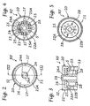
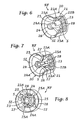
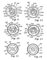
- the flow regulator RF is illustrated in various views in Figures 2 to 8.
- the said regulator is represented without its own membrane for regulating the flow (hereinafter designated by 26).
- the flow regulator RF is of the variable-section type, which exploits deformation of an elastically deformable membrane, which is subjected to the action of the flow for self-regulation of passage of the liquid.
- the body itself of the regulator RF is shaped for silencing the flow of the liquid that passes.
- the flow regulator RF has a body 20 with a substantially cylindrical outer wall, designated by 21. From an intermediate area of the wall 21 there branches off, towards the inside of the body 20 an annular wall, designated by 22A, which extends substantially at right angles to the cylindrical wall 21. From the internal end of the annular wall 22A, there then branches off a tubular wall 22B, which extends towards the bottom end of the body 20, basically at right angles to the annular wall 22A.
- the internal diameter of the outer wall 21 decreases progressively from the top end of the body 20 up to the annular wall 22A. Instead, the internal diameter of the outer wall 21 increases progressively from the annular wall 22A up to the bottom end of the body 20.
- the tubular wall 22B which has an external diameter that decreases progressively, terminates in a bottom wall 23 of the body 20, which extends substantially parallel to the stretch of annular wall 22A.
- a substantially circular second wall which is designed to form a pin 24 having a substantially cylindrical shape and having an internal blind hole.
- the supports 25 have a cross section shaped substantially like an arc of circumference and are formed in areas set opposite with reference to the pin 24.
- each support 25 there extends a respective baffle or radial diaphragm designated by 25A.
- the reference number 26 designates an elastically deformable membrane having an annular shape, the central hole 26A of which is fitted on the pin 24.
- the membrane 26 is positioned so that the part of its bottom surface close to the central hole 26A is resting on the top surface of the supports 25. Maintenance of the position of the membrane 26 on the pin 24 is guaranteed by the presence of lateral retention appendages 24A defined on the end of the pin itself.
- the reference number 27 designates projections or spacers having a circular cross section, which rise with calibrated height and distribution from the wall 22 to provide resting points for the part of the bottom surface of the membrane 26 close to the external diameter of the latter.
- the projections 27 have the function of predetermining the value of the flow rate of liquid at which the regulator RF intervenes.
- the reference number 28 designates through holes of smaller cross section than that of the chamber S, i.e., the chamber which extends between 22B and 24-25.
- the holes 28 are defined in the area of the bottom wall 23 not occupied by the pin 24 and by the supports 25.
- the holes 28 preferably have a non-circular cross section, in particular a square cross section, as shown in the example provided in the figures, or a rectangular cross section.
- the cross section of the holes 28 is slightly flared at the ends thereof facing the inside of the chamber S, as may be noted, for instance, in Figures 3, 4 and 8.
- each of the two half-chambers defined by the diaphragms 25A is provided with an equal number of holes 28, namely five.
- the body 20 of the regulator RF has:
- the body 20 of the flow regulator RF is entirely obtained from thermoplastic material by means of a simple operation of moulding by virtue of the fact that the configuration proposed for the body 20 does not present a complex shape and/or complex undercuts. In order to obtain the body 20 it is therefore possible to use moulds for thermoplastic material of simple structure and contained cost.
- the liquid present in the inlet pipe 3 and in the area A is at the pressure of the mains supply, which is greater than the pressure existing in the outlet pipe 4.
- the liquid in the pipe 3 may reach, by means of the aforementioned calibrated holes of the membrane 14, the chamber C.
- the pressure, which is greater in the chamber C than in the outlet pipe 4 maintains the membrane 14 and the cup 13 in the condition which closes the passage that sets the area A in communication with the outlet pipe 4.
- the solenoid valve 1 which is of the normally closed type, must be activated in opening by supplying the solenoid 7.
- the solenoid valve 1 is electrically connected to the washing machine governed by it, which, by means of a programmer of its own, sees to controlling at the right moment (for example, at the start of a washing step) supply of the solenoid 7 by means of the terminals 9.
- the mobile core 11 When the solenoid 7 is supplied, the mobile core 11 is attracted, so opening the central hole 12 of the cup 13. This enables the liquid present in the chamber C to be brought to the same pressure as the one present in the outlet pipe 4 (which, as has been said, is at a pressure lower than the incoming liquid arriving from the pipe 3 and/or present in the area A), under the thrust of which the membrane 14 and the cup 13 move so as to open the passage between the area A and the outlet pipe 4.
- the fact that the flow regulator RF integrates directly the chamber S immediately downstream of the membrane 26, together with the plurality of holes 28 of small cross section in the bottom 23, enables the liquid passing in the flow regulator itself to assume a pressure that is intermediate between the pressures present in the pipes 3 and 4 and/or the flows to be stabilized, thus making it possible to render passage of the flow silent.
- the membrane 26 is supported centrally by the pin 24, and hence the flow of liquid entering the flow regulator RF enters the chamber S in a radial way passing underneath the membrane itself from its outer edge.
- the flow of liquid passing inside the regulator RF it is possible to identify a number of successive stretches, namely:
- the mobile core 11 When, subsequently, the solenoid 7 is de-energized, the mobile core 11 returns into its original position so that the plug 10 will close the central hole 12 of the cup 13 again. In this condition, the chamber C returns to a pressure higher than the one present in the outlet pipe 4, so causing a movement of the membrane 14 and of the cup 13 into the position where the passage between the chamber A and the outlet pipe 4 is closed. There is thus a return to the initial conditions.
- the diaphragms 25A may be provided should the aim be to contain or prevent formation of any turbulent or circular flow inside the flow regulator RF.
- the said diaphragms may therefore advantageously operate as a preliminary diffusor and may be appropriately shaped for this purpose, as well as possibly contributing to the reinforcement of the central pin 24.
- the diaphragms 25A could be completely omitted, given that the pin 24 and the supports 25 are, in any case, supported by the bottom 23, which is, in turn, integral with or fixed to the internal tubular wall 22B, the latter being supported or fixed by means of the annular wall 22A directly by the external wall 21 of the body 20.
- the annular wall 22A could have a thickness that is decidedly greater than the one illustrated in the attached figures so that its central or internal hole may replace the annular wall 22B.
- the bottom wall 23 would therefore be attached to the wall 22A or else to the outer wall 21.
- the device RF could envisage flow-regulating means of a different type, in accordance with techniques in themselves known, such as an O-ring or a mobile cup with a spring.
- the flow regulator RF could be conceived for operating also as a filter.
- the flow regulator RF in order to prevent any possible early clogging thereof, there could be provided an adequate or greater number of holes 28 within the chamber S.
- the said holes will be appropriately sized, as regards their number and their location, by possibly providing some of them also on the wall 22B of the chamber S (which may be more elongated than what is shown in the case of the example provided previously), as well as on the bottom 23.
- the bottom part of the outer wall 21 could be absent or else modified with respect to what has been illustrated.
Landscapes
- Engineering & Computer Science (AREA)
- General Engineering & Computer Science (AREA)
- Mechanical Engineering (AREA)
- Physics & Mathematics (AREA)
- General Physics & Mathematics (AREA)
- Automation & Control Theory (AREA)
- Fluid-Driven Valves (AREA)
- Magnetically Actuated Valves (AREA)
Claims (31)
- Dispositif permettant de réguler et stabiliser l'écoulement d'un fluide, en particulier pour des électrovannes, envisagé pour l'insertion dans un tuyau permettant le passage du fluide (3), ledit dispositif (RF) définissant de manière interne au moins :dans lequel ledit dispositif (RF) définit en outre, en aval dudit étranglement (22A) et dudit moyen de régulation de débit (26), une chambre (S) ayant une section transversale inférieure à celle dudit passage d'entrée (SI), ladite chambre (S) étant délimitée à son extrémité longitudinale opposée audit moyen de régulation de débit (26) par une paroi inférieure (23),un passage d'entrée (SI), ayant une première section ;une section d'étranglement (22A) en aval dudit passage d'entrée (SI), un moyen de régulation de débit (26) étant fourni en correspondance avec ledit étranglement, en particulier une membrane d'étanchéité (26) ; etun moyen de support (24, 25) pour ledit moyen de régulation de débit (26), en correspondance avec ledit étranglement (22A) ;
caractérisé en ce que ledit dispositif (RF) comprend un corps unique (20), ledit passage d'entrée (SI) est défini par une paroi externe (21) dudit corps unique (20), en particulier une paroi sensiblement tubulaire ou cylindrique, qui entoure au moins en partie ledit moyen de régulation de débit (26), et ladite chambre (S) est munie d'une pluralité de passages de sortie (28) ayant une section inférieure à celle de ladite chambre (S). - Dispositif selon la revendication 1, caractérisé en ce qu'une pluralité desdits passages de sortie (28) est définie dans ladite paroi inférieure (23).
- Dispositif selon la revendication 1, caractérisé en ce que lesdits moyens de support (24, 25) comprennent au moins un élément formant broche (24), qui s'élève à partir de ladite paroi inférieure (23) en direction de l'intérieur dudit corps (20).
- Dispositif selon la revendication 1, caractérisé en ce que lesdits moyens de support (24, 25) comprennent au moyen un élément formant broche (24), supporté par ladite paroi inférieure (23).
- Dispositif selon la revendication 1, caractérisé en ce que lesdits moyens de support (24, 25) définissent d'une manière interne au moins un trou borgne.
- Dispositif selon la revendication 1 ou la revendication 3, caractérisé en ce que lesdits moyens de support (24, 25) comprennent une ou plusieurs projections (25), qui s'élèvent à partir de ladite paroi inférieure (23) en direction de l'intérieur dudit corps (20), dans lequel, en particulier, au moins une partie dudit moyen de régulation (26) est fixée ou s'étend en haut desdites projections (25).
- Dispositif selon la revendication 4 et la revendication 6, caractérisé en ce que lesdites projections (15) sont formées dans des zones opposées audit élément formant broche (24).
- Dispositif selon la revendication 1 ou la revendication 2, caractérisé en ce que lesdits passages de sortie (28) sont définis dans des zones latérales de ladite paroi inférieure (23), lesdits moyens de support (24, 25) s'élevant à partir de la zone centrale de ladite paroi inférieure (23).
- Dispositif selon la revendication 1 ou la revendication 2, caractérisé en ce que lesdits passages de sortie (28) ont une section transversale non circulaire, en particulier une section transversale rectangulaire ou carrée, et/ou en ce que leur section transversale est évasée à l'extrémité de celle-ci faisant face à l'intérieur de ladite chambre (S).
- Dispositif selon la revendication 1, caractérisé en ce que ladite chambre (25) a au moins un élément de subdivision interne (25A), dans lequel en particulier un certain nombre d'éléments de subdivision est fourni, sous la forme de diaphragmes internes (25A) de ladite chambre (S), chacun s'étendant de manière radiale à partir desdits moyens de support (24, 25).
- Dispositif selon la revendication 10, caractérisé en ce que ladite chambre (S) est divisée, au moyen de deux desdits éléments de subdivision (25A) voire davantage, en deux demi-chambres voire davantage.
- Dispositif selon la revendication 11, caractérisé en ce que lesdites demi-chambres ont un nombre égal de dits passages de sortie (28).
- Dispositif selon la revendication 11, caractérisé en ce que lesdites demi-chambres ont un nombre différent de dits passages de sortie (28).
- Dispositif selon la revendication 3 et la revendication 4, caractérisé en ce que lesdits moyens de régulation comprennent une membrane d'étanchéité (26) ayant un trou central (26A) sur ledit élément de broche (24), dans lequel une partie de la surface inférieure de ladite membrane d'étanchéité (26) proche dudit trou (26A) repose localement sur la surface supérieure desdites projections (25).
- Dispositif selon la revendication 1, caractérisé en ce que, s'élevant à partir d'une surface dudit étranglement (22A), se trouvent des dégagements ou entretoises (27) pour lesdits moyens de régulation (26), ayant en particulier une section transversale circulaire.
- Dispositif selon les revendications 14 et 15, caractérisé en ce que lesdits dégagements (27) constituent des points de support local pour au moins une partie de la surface inférieure de ladite membrane d'étanchéité (26) proche du diamètre externe de cette dernière.
- Dispositif selon la revendication 15, caractérisé en ce que le nombre desdits passages de sortie (28) est plus concentré dans les zones de ladite paroi inférieure (23) auxquelles correspondent des zones dudit étranglement (22A) où les dégagements (27) sont définis.
- Dispositif selon la revendication 1, caractérisé en ce qu'une paroi annulaire (22A) s'écarte de ladite paroi externe (21), en direction de l'intérieur dudit corps (20), ladite paroi annulaire (22A) définissant ledit étranglement, ladite paroi annulaire s'étendant dans une direction sensiblement perpendiculaire à ladite paroi externe (21).
- Dispositif selon la revendication 18, caractérisé en ce que, de l'extrémité interne de ladite paroi annulaire (22A), une paroi tubulaire (22B) s'écarte, et s'étend en direction de l'extrémité dudit corps (20) opposée à celle dans laquelle lesdits moyens de régulation (26) sont positionnés, dans laquelle en particulierladite paroi tubulaire (22B) est sensiblement perpendiculaire à ladite paroi annulaire (22A), et/ouladite paroi inférieure (23) est prévue au niveau de l'extrémité inférieure de ladite paroi tubulaire (22B).
- Dispositif selon la revendication 2, caractérisé en ce qu'au moins une paroi (24, 25) dudit corps (20) s'élève de manière centrale à partir de ladite paroi inférieure (23) dans ladite chambre (S), lesdits passages de sortie (28) étant définis dans une zone de ladite paroi inférieure (23) non occupée par ladite au moins une paroi (24, 25).
- Dispositif selon la revendication 18, caractérisé en ce quela section de passage ou le diamètre interne de ladite paroi externe (21) diminue progressivement à partir de la partie dudit corps (20) dans laquelle lesdits moyens de régulation (26) sont agencés contre ladite paroi annulaire (22A), et/oule diamètre interne de ladite paroi externe (21) augmente progressivement à partir de ladite paroi annulaire (22A) jusqu'à la partie dudit corps (20) opposée à celle dans laquelle lesdits moyens de régulation (26) sont agencés.
- Dispositif selon la revendication 19, caractérisé en ce que la section ou le diamètre externe de ladite paroi tubulaire (22B) diminue progressivement à partir de ladite paroi annulaire (22A) jusqu'à la paroi inférieure (23).
- Dispositif selon la revendication 1, caractérisé en ce que ledit corps (20) est entièrement obtenu en une seule pièce de matériau thermoplastique moulé.
- Dispositif selon la revendication 18, caractérisé en ce que, entre ladite paroi inférieure (23) et ladite paroi externe (21), des éléments de raccord radiaux ou chicanes sont fournis.
- Dispositif selon la revendication 19, caractérisé en ce que, entre ladite paroi tubulaire (22B) et ladite paroi externe (21), des éléments de raccord radiaux ou chicanes sont fournis.
- Dispositif selon la revendication 1 ou la revendication 2, caractérisé en ce que lesdits passages de sortie (28) sont également prévus dans le but de filtrer le fluide.
- Dispositif selon la revendication 1 ou la revendication 19, caractérisé en ce que les passages de sortie sont également prévus sur au moins une paroi latérale (22B) de ladite chambre (S) ou dans ladite paroi annulaire (22B).
- Vanne hydraulique ayant un corps respectif définissant un tuyau d'entrée (3), un tuyau de sortie (4), des moyens d'ouverture/fermeture (13, 14) installés de manière opérationnelle entre ledit tuyau d'entrée (3) et ledit tuyau de sortie (4), des moyens d'actionnement (7), qui sont opérationnels pour assurer une commutation desdits moyens d'ouverture/fermeture (13, 14), caractérisée en ce qu'elle comprend, à l'intérieur d'au moins un desdits tuyaux (3, 4), un dispositif permettant de réguler et stabiliser l'écoulement d'un fluide (RF) construit selon une ou plusieurs des revendications précédentes.
- Vanne selon la revendication 28, caractérisée en ce qu'elle est une électrovanne du type déséquilibré ou piloté.
- Vanne selon la revendication 28 ou la revendication 29, caractérisée en ce que, en amont dudit dispositif régulateur de débit (RF), se trouve un filtre (6) dans ledit tuyau (3).
- Procédé de régulation et/ou de stabilisation d'écoulement d'un fluide, avec la diminution simultanée du bruit de ce dernier, au moyen d'un régulateur de débit (RF) ayant un corps (20) qui est monté dans un tuyau (3) et a une direction axiale dans ledit tuyau (3), dans lequel, à l'intérieur du corps (20) du régulateur de débit (RF), un écoulement du fluide est induit pour suivre :caractérisé en ce que l'écoulement du fluide, à l'extrémité de la troisième section de trajet, est divisé en un certain nombre d'écoulements partiels, au moyen d'une pluralité d'ouvertures (27) définies dans un fond (23) de ladite chambre (S), lesdits écoulements partiels se recombinant à la sortie desdites ouvertures (27).une première section de trajet, qui s'étend de manière axiale dans un passage d'entrée (SI) du corps (20) du régulateur (RF) ;une deuxième section de trajet, qui s'étend de manière radiale, en particulier à partir de l'extérieur en direction du centre du corps (20) du régulateur (RF), entre une section d'étranglement (22A) qui se trouve en aval du passage d'entrée (SI) et le moyen de régulation de débit (26) ; etune troisième section de trajet, qui s'étend de manière axiale dans une chambre (S) qui a une section plus petite que celle du passage d'entrée (SI) et est définie en aval du moyen de régulation (26) et de la section d'étranglement (22A) ;
Applications Claiming Priority (3)
| Application Number | Priority Date | Filing Date | Title |
|---|---|---|---|
| IT2001TO001206A ITTO20011206A1 (it) | 2001-12-21 | 2001-12-21 | Dispositivo regolatore del flusso di un fluido, in particolare per elettrovalvole. |
| ITTO20011206 | 2001-12-21 | ||
| PCT/IB2002/005376 WO2003054436A1 (fr) | 2001-12-21 | 2002-12-13 | Dispositif permettant de reguler l'ecoulement d'un fluide, notamment pour les electrovannes |
Publications (2)
| Publication Number | Publication Date |
|---|---|
| EP1456576A1 EP1456576A1 (fr) | 2004-09-15 |
| EP1456576B1 true EP1456576B1 (fr) | 2005-11-09 |
Family
ID=11459349
Family Applications (1)
| Application Number | Title | Priority Date | Filing Date |
|---|---|---|---|
| EP02788351A Expired - Lifetime EP1456576B1 (fr) | 2001-12-21 | 2002-12-13 | Dispositif permettant de reguler l'ecoulement d'un fluide, notamment pour les electrovannes |
Country Status (7)
| Country | Link |
|---|---|
| US (1) | US7143992B2 (fr) |
| EP (1) | EP1456576B1 (fr) |
| AU (1) | AU2002353330A1 (fr) |
| DE (1) | DE60207296T2 (fr) |
| ES (1) | ES2252528T3 (fr) |
| IT (1) | ITTO20011206A1 (fr) |
| WO (1) | WO2003054436A1 (fr) |
Families Citing this family (20)
| Publication number | Priority date | Publication date | Assignee | Title |
|---|---|---|---|---|
| WO2004005628A2 (fr) * | 2002-06-24 | 2004-01-15 | Arichell Technologies, Inc. | Systemes de distribution d'eau automatises a commande asservie |
| US8113225B2 (en) * | 2007-03-07 | 2012-02-14 | Zurn Industries, Llc | Flush valve actuator for low-flow urinal |
| JP5307517B2 (ja) * | 2008-11-14 | 2013-10-02 | カヤバ工業株式会社 | ソレノイド |
| AU2009332751B2 (en) * | 2008-12-22 | 2014-01-30 | Artemis Intelligent Power Limited | Valve assembly |
| KR101093683B1 (ko) * | 2009-08-28 | 2011-12-15 | 우성전기공업 주식회사 | 전자석식 급수밸브 |
| KR101285748B1 (ko) * | 2011-09-27 | 2013-07-18 | 우성전기공업 주식회사 | 유수 제어기능을 갖는 전자석 밸브 |
| ITTO20130002A1 (it) | 2013-01-02 | 2014-07-03 | Indesit Co Spa | Procedimento per controllare il riempimento con acqua di un elettrodomestico a conduzione d'acqua |
| ITTO20130003A1 (it) | 2013-01-02 | 2014-07-03 | Indesit Co Spa | Procedimento per controllare il riempimento con acqua di un elettrodomestico a conduzione d'acqua |
| ITTO20130039A1 (it) | 2013-01-17 | 2014-07-18 | Indesit Co Spa | Procedimento per controllare il riempimento di acqua in un elettrodomestico a conduzione d'acqua |
| DE102014216443A1 (de) * | 2014-08-19 | 2016-02-25 | Robert Bosch Gmbh | Elektromagnetisch betätigbares Ventil zum Eindosieren eines Gases sowie Verfahren zur Herstellung eines solchen Ventils |
| US9822885B2 (en) | 2014-08-29 | 2017-11-21 | Automatic Switch Company | Flow rib in valves |
| KR20160031596A (ko) * | 2014-09-12 | 2016-03-23 | 동부대우전자 주식회사 | 감압 및 필터 기능을 갖는 세탁기 급수밸브용 통합장치 및 그 제조방법 |
| FR3054609A1 (fr) * | 2016-07-29 | 2018-02-02 | Plastic Omnium Advanced Innovation & Res | Regulateur de debit de ventilation pour un reservoir pressurise de vehicule. |
| DE202017101427U1 (de) * | 2017-03-13 | 2018-06-14 | Neoperl Gmbh | Durchflussmengenregler |
| DE102017105273A1 (de) | 2017-03-13 | 2018-09-13 | Neoperl Gmbh | Durchflussmengenregler |
| US11255399B2 (en) * | 2018-03-14 | 2022-02-22 | Zf Friedrichshafen Ag | Damping valve for a vibration damper |
| US12007038B2 (en) * | 2019-09-23 | 2024-06-11 | Jiangmen Tiandi Electrical Appliance Co., Ltd | Water inlet solenoid valve capable of improving electromagnetic attraction and implementing method therefor |
| CN112539292B (zh) * | 2019-09-23 | 2022-02-11 | 江门市甜的电器有限公司 | 一种可提升电磁吸力的进水电磁阀及实现方法 |
| US12443208B2 (en) | 2023-02-08 | 2025-10-14 | Rain Bird Corporation | Control zone devices, systems and methods |
| US12498049B2 (en) | 2024-03-29 | 2025-12-16 | Rain Bird Corporation | Zone control devices, systems and methods |
Family Cites Families (10)
| Publication number | Priority date | Publication date | Assignee | Title |
|---|---|---|---|---|
| US2489542A (en) * | 1946-07-26 | 1949-11-29 | Dole Valve Co | Flow control means and method |
| US4105721A (en) * | 1975-06-16 | 1978-08-08 | Schliebe Rae D | Venturi fitting for the aeration of water |
| JPS5635832A (en) | 1979-08-27 | 1981-04-08 | Kayaba Ind Co Ltd | Hydraulic shock absorber |
| US4248270A (en) * | 1980-01-11 | 1981-02-03 | The Singer Company | Reduced noise water valve provided with flow control |
| GB8819838D0 (en) | 1988-08-20 | 1988-09-21 | Eaton Sa Monaco | Noise limiter |
| US5070909A (en) | 1990-06-11 | 1991-12-10 | Davenport Robert G | Low recovery rotary control valve |
| US5487528A (en) * | 1993-04-22 | 1996-01-30 | Emerson Electric Co. | Quiet appliance water valve |
| JP3130450B2 (ja) | 1995-06-30 | 2001-01-31 | 株式会社クボタ | 流量制御弁 |
| US5813500A (en) | 1996-03-25 | 1998-09-29 | Tenneco Automotive Inc. | Anti-swish mechanism for a damper |
| US5813652A (en) * | 1996-10-22 | 1998-09-29 | Emerson Electric Co. | Apparatus for suppressing noise generated by a flow of water through a water valve |
-
2001
- 2001-12-21 IT IT2001TO001206A patent/ITTO20011206A1/it unknown
-
2002
- 2002-12-13 EP EP02788351A patent/EP1456576B1/fr not_active Expired - Lifetime
- 2002-12-13 DE DE60207296T patent/DE60207296T2/de not_active Expired - Lifetime
- 2002-12-13 ES ES02788351T patent/ES2252528T3/es not_active Expired - Lifetime
- 2002-12-13 WO PCT/IB2002/005376 patent/WO2003054436A1/fr not_active Ceased
- 2002-12-13 AU AU2002353330A patent/AU2002353330A1/en not_active Abandoned
- 2002-12-13 US US10/498,996 patent/US7143992B2/en not_active Expired - Fee Related
Also Published As
| Publication number | Publication date |
|---|---|
| ITTO20011206A0 (it) | 2001-12-21 |
| EP1456576A1 (fr) | 2004-09-15 |
| AU2002353330A1 (en) | 2003-07-09 |
| DE60207296D1 (de) | 2005-12-15 |
| ES2252528T3 (es) | 2006-05-16 |
| DE60207296T2 (de) | 2006-07-27 |
| WO2003054436A1 (fr) | 2003-07-03 |
| ITTO20011206A1 (it) | 2003-06-21 |
| US7143992B2 (en) | 2006-12-05 |
| US20050082504A1 (en) | 2005-04-21 |
Similar Documents
| Publication | Publication Date | Title |
|---|---|---|
| EP1456576B1 (fr) | Dispositif permettant de reguler l'ecoulement d'un fluide, notamment pour les electrovannes | |
| EP1038134B1 (fr) | Vanne a ecoulement proportionnel a large plage de debits | |
| US5368071A (en) | Wash-basin faucet | |
| US5145145A (en) | Pilot operated electrically actuated value assembly | |
| CA1317583C (fr) | Robinet a commande electrique | |
| US4981155A (en) | Electrically operated valve assembly | |
| CA1270238A (fr) | Clapet a solenoide | |
| KR20100022652A (ko) | 전자제어 현가장치용 솔레노이드 밸브 | |
| JP7532078B2 (ja) | 電磁弁 | |
| KR20110027040A (ko) | 솔레노이드 밸브 | |
| US3062992A (en) | Unitized fluid control valve | |
| CN219102058U (zh) | 一种电磁阀 | |
| CN217520074U (zh) | 调水装置及热水器 | |
| JP2002213634A (ja) | 電磁弁構造 | |
| CN223447802U (zh) | 灌溉阀 | |
| JPS605162Y2 (ja) | 複動電磁弁 | |
| CN218178044U (zh) | 一种龙头易安装结构 | |
| KR200416106Y1 (ko) | 동축 유동형 솔레노이드 밸브 | |
| CN218236189U (zh) | 双特性流量调节阀 | |
| CN219493221U (zh) | 一种增加比例阀电磁力的结构 | |
| KR200407000Y1 (ko) | 온수분배기용 자동 온도조절밸브 조립체 | |
| JP7387244B2 (ja) | 電磁弁 | |
| KR20110027043A (ko) | 솔레노이드 밸브 | |
| JP2001235045A (ja) | 多連式電磁給水弁装置 | |
| JPH0861544A (ja) | 流体制御弁における弁構造 |
Legal Events
| Date | Code | Title | Description |
|---|---|---|---|
| PUAI | Public reference made under article 153(3) epc to a published international application that has entered the european phase |
Free format text: ORIGINAL CODE: 0009012 |
|
| 17P | Request for examination filed |
Effective date: 20040709 |
|
| AK | Designated contracting states |
Kind code of ref document: A1 Designated state(s): AT BE BG CH CY CZ DE DK EE ES FI FR GB GR IE IT LI LU MC NL PT SE SI SK TR |
|
| AX | Request for extension of the european patent |
Extension state: AL LT LV MK RO |
|
| RIN1 | Information on inventor provided before grant (corrected) |
Inventor name: SASSONE, LUIGI Inventor name: SAVINI, PAOLO |
|
| GRAP | Despatch of communication of intention to grant a patent |
Free format text: ORIGINAL CODE: EPIDOSNIGR1 |
|
| GRAS | Grant fee paid |
Free format text: ORIGINAL CODE: EPIDOSNIGR3 |
|
| GRAA | (expected) grant |
Free format text: ORIGINAL CODE: 0009210 |
|
| AK | Designated contracting states |
Kind code of ref document: B1 Designated state(s): DE ES FR IT |
|
| REF | Corresponds to: |
Ref document number: 60207296 Country of ref document: DE Date of ref document: 20051215 Kind code of ref document: P |
|
| REG | Reference to a national code |
Ref country code: ES Ref legal event code: FG2A Ref document number: 2252528 Country of ref document: ES Kind code of ref document: T3 |
|
| ET | Fr: translation filed | ||
| PLBE | No opposition filed within time limit |
Free format text: ORIGINAL CODE: 0009261 |
|
| STAA | Information on the status of an ep patent application or granted ep patent |
Free format text: STATUS: NO OPPOSITION FILED WITHIN TIME LIMIT |
|
| 26N | No opposition filed |
Effective date: 20060810 |
|
| PGFP | Annual fee paid to national office [announced via postgrant information from national office to epo] |
Ref country code: IT Payment date: 20101206 Year of fee payment: 9 |
|
| PGFP | Annual fee paid to national office [announced via postgrant information from national office to epo] |
Ref country code: DE Payment date: 20101208 Year of fee payment: 9 |
|
| PGFP | Annual fee paid to national office [announced via postgrant information from national office to epo] |
Ref country code: FR Payment date: 20111219 Year of fee payment: 10 |
|
| PGFP | Annual fee paid to national office [announced via postgrant information from national office to epo] |
Ref country code: ES Payment date: 20120116 Year of fee payment: 10 |
|
| REG | Reference to a national code |
Ref country code: FR Ref legal event code: ST Effective date: 20130830 |
|
| REG | Reference to a national code |
Ref country code: DE Ref legal event code: R119 Ref document number: 60207296 Country of ref document: DE Effective date: 20130702 |
|
| PG25 | Lapsed in a contracting state [announced via postgrant information from national office to epo] |
Ref country code: DE Free format text: LAPSE BECAUSE OF NON-PAYMENT OF DUE FEES Effective date: 20130702 |
|
| PG25 | Lapsed in a contracting state [announced via postgrant information from national office to epo] |
Ref country code: FR Free format text: LAPSE BECAUSE OF NON-PAYMENT OF DUE FEES Effective date: 20130102 |
|
| PG25 | Lapsed in a contracting state [announced via postgrant information from national office to epo] |
Ref country code: IT Free format text: LAPSE BECAUSE OF NON-PAYMENT OF DUE FEES Effective date: 20121213 |
|
| REG | Reference to a national code |
Ref country code: ES Ref legal event code: FD2A Effective date: 20140527 |
|
| PG25 | Lapsed in a contracting state [announced via postgrant information from national office to epo] |
Ref country code: ES Free format text: LAPSE BECAUSE OF NON-PAYMENT OF DUE FEES Effective date: 20121214 |