EP1456690B1 - Appareil de mesure de distance laser - Google Patents
Appareil de mesure de distance laser Download PDFInfo
- Publication number
- EP1456690B1 EP1456690B1 EP02798259A EP02798259A EP1456690B1 EP 1456690 B1 EP1456690 B1 EP 1456690B1 EP 02798259 A EP02798259 A EP 02798259A EP 02798259 A EP02798259 A EP 02798259A EP 1456690 B1 EP1456690 B1 EP 1456690B1
- Authority
- EP
- European Patent Office
- Prior art keywords
- unit
- frequency
- sideband modulation
- oscillator
- generated
- Prior art date
- Legal status (The legal status is an assumption and is not a legal conclusion. Google has not performed a legal analysis and makes no representation as to the accuracy of the status listed.)
- Expired - Lifetime
Links
- 238000000034 method Methods 0.000 claims 2
- 238000004519 manufacturing process Methods 0.000 claims 1
- 238000005259 measurement Methods 0.000 description 3
- 239000013598 vector Substances 0.000 description 2
- 230000005540 biological transmission Effects 0.000 description 1
- 238000011156 evaluation Methods 0.000 description 1
- 238000009434 installation Methods 0.000 description 1
- 230000002452 interceptive effect Effects 0.000 description 1
- 230000005693 optoelectronics Effects 0.000 description 1
- 238000001228 spectrum Methods 0.000 description 1
Images


Classifications
-
- G—PHYSICS
- G01—MEASURING; TESTING
- G01S—RADIO DIRECTION-FINDING; RADIO NAVIGATION; DETERMINING DISTANCE OR VELOCITY BY USE OF RADIO WAVES; LOCATING OR PRESENCE-DETECTING BY USE OF THE REFLECTION OR RERADIATION OF RADIO WAVES; ANALOGOUS ARRANGEMENTS USING OTHER WAVES
- G01S17/00—Systems using the reflection or reradiation of electromagnetic waves other than radio waves, e.g. lidar systems
- G01S17/02—Systems using the reflection of electromagnetic waves other than radio waves
- G01S17/06—Systems determining position data of a target
- G01S17/08—Systems determining position data of a target for measuring distance only
- G01S17/32—Systems determining position data of a target for measuring distance only using transmission of continuous waves, whether amplitude-, frequency-, or phase-modulated, or unmodulated
- G01S17/36—Systems determining position data of a target for measuring distance only using transmission of continuous waves, whether amplitude-, frequency-, or phase-modulated, or unmodulated with phase comparison between the received signal and the contemporaneously transmitted signal
-
- G—PHYSICS
- G01—MEASURING; TESTING
- G01S—RADIO DIRECTION-FINDING; RADIO NAVIGATION; DETERMINING DISTANCE OR VELOCITY BY USE OF RADIO WAVES; LOCATING OR PRESENCE-DETECTING BY USE OF THE REFLECTION OR RERADIATION OF RADIO WAVES; ANALOGOUS ARRANGEMENTS USING OTHER WAVES
- G01S7/00—Details of systems according to groups G01S13/00, G01S15/00, G01S17/00
- G01S7/48—Details of systems according to groups G01S13/00, G01S15/00, G01S17/00 of systems according to group G01S17/00
- G01S7/491—Details of non-pulse systems
-
- G—PHYSICS
- G01—MEASURING; TESTING
- G01S—RADIO DIRECTION-FINDING; RADIO NAVIGATION; DETERMINING DISTANCE OR VELOCITY BY USE OF RADIO WAVES; LOCATING OR PRESENCE-DETECTING BY USE OF THE REFLECTION OR RERADIATION OF RADIO WAVES; ANALOGOUS ARRANGEMENTS USING OTHER WAVES
- G01S7/00—Details of systems according to groups G01S13/00, G01S15/00, G01S17/00
- G01S7/48—Details of systems according to groups G01S13/00, G01S15/00, G01S17/00 of systems according to group G01S17/00
- G01S7/491—Details of non-pulse systems
- G01S7/4911—Transmitters
Definitions
- the invention relates to a laser distance measuring device according to the preamble of claim 1.
- Laser distance measuring devices which have a transmitter unit with a laser, a receiver unit and a single sideband modulation unit.
- a modulation frequency of the transmitter unit can be generated with a single-sideband modulation frequency generated by an oscillator unit which simultaneously corresponds to a low frequency or a useful frequency for phase determination, and with a carrier frequency.
- the demodulation frequency of the receiver unit uses the original carrier frequency.
- a laser range finder which comprises a transmitter unit with a laser and a receiver unit. It also includes an SSB filter (Single-sideband filter or single-sideband modulation filter), which generates a one-sideband modulation frequency in combination with a carrier frequency in the provision of a transmission signal. After receiving the transmitted signal reflected in the receiving unit in the receiver unit is a LF useful frequency by the difference of Modulation frequency given with the carrier frequency.
- SSB filter Single-sideband filter or single-sideband modulation filter
- the invention is based on a laser distance measuring device which has a transmitter unit with at least one laser and a receiver unit and a single-sideband modulation unit with which a first single-sideband modulation frequency generated by an oscillator unit and with a carrier frequency a modulation frequency of the transmitter unit designed as a sideband can be generated.
- At least one further frequency can be generated by means of the oscillator unit, and a demodulation frequency of the receiver unit designed as a sideband can be generated via the single-sideband modulation unit with the further frequency, wherein an AF useful signal can be generated by mixing the modulation frequency and the demodulation frequency.
- a distance between the carrier frequency and the modulation frequency and the demodulation frequency can be selected independently of a useful frequency, and although this can be selected to be larger than the useful frequency in particular.
- Disturbance variables can be easily eliminated or filtered out, in particular if at least one second single-sideband modulation frequency can be generated with the oscillator unit, and a demodulation frequency of the receiver unit can be generated via the single-sideband modulation unit having the second single-sideband modulation frequency. It can be achieved with a low-cost laser rangefinder highly accurate results. Instead of having a second single-sideband modulation frequency, the demodulation frequency could also be generated with a second carrier frequency.
- the oscillator unit a single highly accurate oscillator, from which at least both single-sideband modulation frequencies can be generated and / or the oscillator unit is coupled with at least two dividers with different factors over which the Einurgibandmodulationsfrequenzen be generated, particularly compact, cost-effective and easy Laserentfernungsmeß maretz can be achieved.
- the oscillator unit has at least one LF generator or low-frequency generator and at least one single-sideband modulation frequency can be generated via a synthetic frequency shift, a high degree of flexibility in frequency generation can be achieved.
- the oscillator unit has a PLL unit or a phase-locked loop unit for generating the carrier frequency, whereby it can be generated with a cost-effective circuit.
- at least two carrier frequencies can be generated from an oscillator unit having at least two PLL units.
- a sinusoidal signal can be generated via the oscillator unit and the single-sideband modulation unit.
- other signal forms which appear reasonable to the person skilled in the art are also conceivable.
- filters can be at least reduced or completely avoided with sinusoidal signals. Additional components, space, weight, installation costs and costs can be saved.
- the solution according to the invention is suitable for all laser distance measuring devices which appear to be suitable to the person skilled in the art, but in particular for hand-held laser distance measuring devices, which nevertheless can be made cost-effective and compact with the solution according to the invention with a high measuring accuracy.
- Fig. 1 shows a laser rangefinder with a housing 30 arranged in the transmitter unit 10 for emitting a laser measurement signal ( Fig. 1 and 2 ).
- the transmitter unit 10 has a laser diode not shown in detail and a collimating lens, with the aid of which the measurement signal can be bundled through an outlet channel.
- the laser rangefinder has a receiver unit 12 with a lens, not shown, which captures reflected on an object Meßsignal shares and directs to an opto-electronic converter.
- the converter which is preferably designed as an avalanche photodiode, receives the measured signal components and supplies them in electrical form to a likewise unillustrated arithmetic unit or evaluation unit.
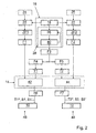
- the laser distance measuring device has a single-sideband modulation unit 14 with which a modulation frequency S1 is generated by a single-sideband modulation frequency ZF1 generated by an oscillator unit 16 and a carrier frequency T1.
- the transmitter unit 10 can be generated ( Fig. 2 and 3 ).
- a second single-sideband modulation frequency ZF2 can be generated with the oscillator unit 16, wherein the single-sideband modulation unit 14 has the second single-sideband modulation frequency ZF2 a demodulation frequency S2 of the receiver unit 12 can be generated.
- the oscillator unit 16 has a single highly accurate oscillator 18, from which the single-sideband modulation frequencies ZF1, ZF2 can be generated, via two dividers 20, 22 with different factors, which are coupled to the oscillator unit 16.
- the single-sideband modulation frequency ZF1 and / or ZF2 could also be generated synthetically by means of an LF generator 24, 26, as shown in FIG Fig. 2 is indicated.
- the dividers 20, 22 could be provided with the same factor.
- the carrier frequency T1 for the transmitter unit 10 and a carrier frequency T2. can be generated for the receiver unit 12, via a PLL unit 28 of the oscillator unit 16, which has a PLL block 38 or a phase-locked loop block and a VCO block 40 or a voltage-controlled oscillator block having.
- the carrier frequencies T1, T2 could also be generated from separate oscillators.
- the single-sideband modulation unit 14 which has a first single-sideband modulator 42 for the transmitter unit 10 and a second single sideband modulator 44 for the receiver unit 12, are respectively connected in the path 46 of the transmitter unit 10 and in the path 48 of the receiver unit 12, filters F1, F2, to select from the single-sideband modulation frequencies ZF1 , ZF2, which may also be referred to as intermediate frequencies, to filter out unwanted frequencies.
- the oscillator unit 16 are three filters downstream F3, F4, F5, namely a zen-traler Filter F3 immediately after the VCO block 40 and a respective filter F4 and F5 for the path 46 of the transmitter unit 10 and the path 48 of the receiver unit 12. Further, after the single-sideband modulation unit 14 of the transmitter unit 10 and the receiver unit 12 are each a filter F6, F7 pre-activated.
- the paths 46, 48 for the transmitter unit 10 and the receiver unit 12 could also be interchanged or the frequency S2 for modulation of the transmitter unit 10 and the frequency S1 for demodulation of the receiver unit 12 could be used.
- filters F1 F5 could simply be saved.
- filters may be required in various arrangements and combinations that appear appropriate to those skilled in the art, particularly in paths 46, 48 of transmitter unit 10 and receiver unit 12. Filters F1-F5 are particularly useful to achieve a particular measurement accuracy and limit the bandwidth.
- the single-sideband modulator 42 of the single-sideband modulation unit 14 displaces the carrier frequency T1 with the single-sideband modulation frequency ZF1, resulting in the modulation frequency S1 of the transmitter unit 10, the frequency S1 'or sidebands S1 and S1' and the carrier frequency T1 *.
- the single-sideband modulator 44 of the single-sideband modulation unit 14 the carrier frequency T2 with the One sideband modulation frequency ZF2 shifted, whereby this demodulation frequency S2 of the receiver unit 12, the frequency S2 'and the sidebands S2 and S2' and the carrier frequency T1 * arise.
- the carrier frequencies T1, T2 have a greater amplitude than the carrier frequencies T1 *, T2 *, otherwise the carrier frequencies T1, T2, T1 *, T2 * are identical.
- the carrier frequencies T1 and T2 would coincide.
- the suppressed frequencies S1 ', S2' and the suppressed sidebands are approximately 40 dB below the modulation frequency S1 of the transmitter unit 10 and the demodulation frequency S2 of the receiver unit 12. Furthermore, the suppressed carrier frequencies T1 *, T2 * are typically approximately 40 dB below the modulation frequency S1 of the transmitter unit 10 and the demodulation frequency S2 of the receiver unit 12.
- the vectors lie by multiplying the frequency S1 'and the carrier frequency T2 * and by multiplying the frequency S2' and the carrier frequency T1 * arise, with a suitable choice of the single-sideband modulation frequencies ZF1, ZF2 far above the frequency of the LF useful signal, which is produced by mixing the modulation frequency S1 and the demodulation frequency S2 and in this embodiment is about 4 kHz.
Landscapes
- Engineering & Computer Science (AREA)
- Physics & Mathematics (AREA)
- Computer Networks & Wireless Communication (AREA)
- General Physics & Mathematics (AREA)
- Radar, Positioning & Navigation (AREA)
- Remote Sensing (AREA)
- Electromagnetism (AREA)
- Optical Radar Systems And Details Thereof (AREA)
Claims (7)
- Appareil de télémétrie à laser qui présente une unité d'émission (10) comprenant au moins un laser et une unité de réception (12) ainsi qu'une unité de modulation à bande latérale unique (14) qui permet de générer, avec une première fréquence de modulation à bande latérale unique (ZF1) générée par une unité à oscillateur (16) et avec une fréquence porteuse (T1), une fréquence de modulation (S1) de l'unité d'émission (10) configurée sous la forme d'une bande latérale, caractérisé en ce que l'unité à oscillateur (16) permet de générer au moins une deuxième fréquence de modulation à bande latérale unique (ZF2) et en ce qu'une fréquence de démodulation (S2) de l'unité de réception (12) configurée sous la forme d'une bande latérale peut être générée par le biais de l'unité de modulation à bande latérale unique (14) avec la deuxième fréquence de modulation à bande latérale unique (ZF2), un signal utile BF pouvant être généré en mélangeant la fréquence de modulation (S1) et la fréquence de démodulation (S2).
- Appareil de télémétrie à laser selon la revendication 1, caractérisé en ce que l'unité à oscillateur (16) présente un unique oscillateur (18) de grande précision à partir duquel peuvent être générées au moins les deux fréquences de modulation à bande latérale unique (ZF1, ZF2).
- Appareil de télémétrie à laser selon la revendication 1 ou 2, caractérisé en ce que l'unité à oscillateur (16) est connectée avec deux diviseurs (20, 22) ayant des facteurs différents par le biais desquels peuvent être générées les fréquences de modulation à bande latérale unique (ZF1, ZF2).
- Appareil de télémétrie à laser selon l'une des revendications précédentes, caractérisé en ce que l'unité à oscillateur (16) présente au moins un générateur BF (24, 26) et en ce qu'au moins une fréquence de modulation à bande latérale unique (ZF1, ZF2) peut être générée par le biais d'un décalage de fréquence synthétique.
- Appareil de télémétrie à laser selon l'une des revendications précédentes, caractérisé en ce que l'unité à oscillateur (16) présente une unité à PLL (28) pour générer la fréquence porteuse (T1, T2).
- Appareil de télémétrie à laser selon l'une des revendications précédentes, caractérisé en ce qu'un signal sinusoïdal peut être généré par le biais de l'unité à oscillateur (16) et l'unité de modulation à bande latérale unique (14).
- Procédé pour générer un signal d'un appareil de télémétrie à laser comprenant une unité d'émission (10) une unité de réception (12), une fréquence de modulation (S1) de l'unité d'émission (10) configurée sous la forme d'une bande latérale étant générée avec une unité de modulation à bande latérale unique (14) avec une première fréquence de modulation à bande latérale unique (ZF1) générée par une unité à oscillateur (16) et une fréquence porteuse (T1), caractérisé en ce qu'au moins une deuxième fréquence de modulation à bande latérale unique (ZF2) est générée avec l'unité à oscillateur (16) et en ce qu'une fréquence de démodulation (S2) de l'unité de réception (12) configurée sous la forme d'une bande latérale est générée par le biais de l'unité de modulation à bande latérale unique (14) avec la deuxième fréquence de modulation à bande latérale unique (ZF2) et en ce qu'un signal utile BF est produit en mélangeant la fréquence de modulation (S1) et la fréquence de démodulation (S2).
Applications Claiming Priority (3)
| Application Number | Priority Date | Filing Date | Title |
|---|---|---|---|
| DE10160439 | 2001-12-08 | ||
| DE10160439A DE10160439A1 (de) | 2001-12-08 | 2001-12-08 | Laserentfernungsmeßgerät |
| PCT/DE2002/004460 WO2003050564A1 (fr) | 2001-12-08 | 2002-12-05 | Appareil de mesure de distance laser |
Publications (2)
| Publication Number | Publication Date |
|---|---|
| EP1456690A1 EP1456690A1 (fr) | 2004-09-15 |
| EP1456690B1 true EP1456690B1 (fr) | 2008-12-31 |
Family
ID=7708568
Family Applications (1)
| Application Number | Title | Priority Date | Filing Date |
|---|---|---|---|
| EP02798259A Expired - Lifetime EP1456690B1 (fr) | 2001-12-08 | 2002-12-05 | Appareil de mesure de distance laser |
Country Status (5)
| Country | Link |
|---|---|
| US (1) | US7075626B2 (fr) |
| EP (1) | EP1456690B1 (fr) |
| JP (1) | JP4047813B2 (fr) |
| DE (2) | DE10160439A1 (fr) |
| WO (1) | WO2003050564A1 (fr) |
Families Citing this family (22)
| Publication number | Priority date | Publication date | Assignee | Title |
|---|---|---|---|---|
| US6967573B1 (en) * | 1997-12-24 | 2005-11-22 | Parakan Pty Ltd. | Transmitter and a method for transmitting data |
| USD538188S1 (en) * | 2005-06-09 | 2007-03-13 | Nanjing Chervon Industry Co., Ltd. | Distance finder |
| CA113637S (en) * | 2005-06-09 | 2006-11-16 | Nanjing Chervon Ind Co Ltd | Distance finder target |
| TWD110769S1 (zh) * | 2005-06-10 | 2006-05-11 | 亞洲光學股份有限公司 | 雷射測距儀 |
| DE202005021588U1 (de) * | 2005-09-05 | 2008-10-09 | Robert Bosch Gmbh | Laser-Entfernungsmessgerät |
| USD538690S1 (en) * | 2006-01-16 | 2007-03-20 | Robert Bosch Gmbh | Optical range finder |
| WO2008121919A1 (fr) * | 2007-03-30 | 2008-10-09 | Faro Technologies, Inc. | Appareil de mesure de distance absolue |
| USD574276S1 (en) * | 2007-06-01 | 2008-08-05 | Leica Geosystems Ag | Distance measuring device |
| USD582303S1 (en) * | 2007-07-13 | 2008-12-09 | Chervon Limited | Laser distance finder |
| USD576895S1 (en) * | 2007-09-18 | 2008-09-16 | Leica Geosystems Ag | Laser distance measurement device |
| DE102007055771A1 (de) * | 2007-12-12 | 2009-06-18 | Hilti Aktiengesellschaft | Laserdistanzmesser |
| US8555721B2 (en) * | 2007-12-27 | 2013-10-15 | Scott Taillet | Sound measuring device |
| USD584973S1 (en) * | 2008-04-17 | 2009-01-20 | Spintso International Ab | Digital chronometer and length measurement device |
| CN101881833A (zh) * | 2009-05-07 | 2010-11-10 | 南京德朔实业有限公司 | 光电测距装置 |
| US20110098924A1 (en) * | 2009-10-28 | 2011-04-28 | Callaway Golf Company | Method and device for determining a distance |
| USD670582S1 (en) | 2010-12-07 | 2012-11-13 | Hilti Aktiengesellschaft | Laser distance measurement device |
| USD673062S1 (en) * | 2012-05-18 | 2012-12-25 | Fluke Corporation | Laser distance meter |
| USD716160S1 (en) * | 2012-12-20 | 2014-10-28 | Leica Geosystems Ag | Laser distance measurement device |
| USD724455S1 (en) * | 2014-01-14 | 2015-03-17 | Hilti Aktiengesellschaft | Laser range meter |
| US9606228B1 (en) | 2014-02-20 | 2017-03-28 | Banner Engineering Corporation | High-precision digital time-of-flight measurement with coarse delay elements |
| US10830655B2 (en) | 2018-01-19 | 2020-11-10 | E-Longation, Llc | Method and apparatus for performing field elongation measurements |
| USD931127S1 (en) * | 2020-02-04 | 2021-09-21 | Aukey Technology Co., Ltd | Distance measuring apparatus |
Family Cites Families (13)
| Publication number | Priority date | Publication date | Assignee | Title |
|---|---|---|---|---|
| US3713155A (en) * | 1958-06-23 | 1973-01-23 | Hughes Aircraft Co | Monopulse radar receiver |
| US3644831A (en) * | 1967-10-09 | 1972-02-22 | Gen Electric | Modulation system |
| US3778159A (en) * | 1970-03-10 | 1973-12-11 | Laser Systems & Electronics | Distance measuring apparatus and method utilizing phase comparison of modulated light beams |
| US3733129A (en) * | 1971-02-01 | 1973-05-15 | Hughes Aircraft Co | Laser distance detector |
| US4310920A (en) * | 1977-01-05 | 1982-01-12 | Hayes William A | Single sideband AM-FM stereo modulation system |
| US5152005A (en) * | 1990-01-22 | 1992-09-29 | Motorola, Inc. | High resolution frequency synthesis |
| US5082364A (en) * | 1990-08-31 | 1992-01-21 | Russell James T | Rf modulated optical beam distance measuring system and method |
| US5204642A (en) * | 1991-10-31 | 1993-04-20 | Advanced Micro Devices, Inc. | Frequency controlled recursive oscillator having sinusoidal output |
| JP2584875Y2 (ja) * | 1992-05-26 | 1998-11-11 | 株式会社ニコン | 光波測距装置 |
| US5920840A (en) * | 1995-02-28 | 1999-07-06 | Motorola, Inc. | Communication system and method using a speaker dependent time-scaling technique |
| DE19708163A1 (de) * | 1997-02-28 | 1998-09-10 | Bosch Gmbh Robert | Schaltung zur Signalaufbereitung von in einem Heterodyninterferometer auftretenden Signalen |
| DE19855296C1 (de) | 1998-12-01 | 2000-08-31 | Bosch Gmbh Robert | Vorrichtung zur Entfernungsmessung mittels eines Halbleiterlasers im sichtbaren Wellenlängenbereich nach dem Laufzeitverfahren |
| TW200811179A (en) * | 2006-05-05 | 2008-03-01 | Astrazeneca Ab | mGluR5 modulators VI |
-
2001
- 2001-12-08 DE DE10160439A patent/DE10160439A1/de not_active Withdrawn
-
2002
- 2002-12-05 DE DE50213181T patent/DE50213181D1/de not_active Expired - Lifetime
- 2002-12-05 EP EP02798259A patent/EP1456690B1/fr not_active Expired - Lifetime
- 2002-12-05 WO PCT/DE2002/004460 patent/WO2003050564A1/fr not_active Ceased
- 2002-12-05 US US10/470,429 patent/US7075626B2/en not_active Expired - Lifetime
- 2002-12-05 JP JP2003551565A patent/JP4047813B2/ja not_active Expired - Fee Related
Also Published As
| Publication number | Publication date |
|---|---|
| US20040070747A1 (en) | 2004-04-15 |
| DE10160439A1 (de) | 2003-06-26 |
| DE50213181D1 (de) | 2009-02-12 |
| EP1456690A1 (fr) | 2004-09-15 |
| JP2005512096A (ja) | 2005-04-28 |
| JP4047813B2 (ja) | 2008-02-13 |
| WO2003050564A1 (fr) | 2003-06-19 |
| US7075626B2 (en) | 2006-07-11 |
Similar Documents
| Publication | Publication Date | Title |
|---|---|---|
| EP1456690B1 (fr) | Appareil de mesure de distance laser | |
| DE19811550C2 (de) | Verfahren und Schaltungsanordnung zur Erzeugung von Frequenzsignalen | |
| DE19855296C1 (de) | Vorrichtung zur Entfernungsmessung mittels eines Halbleiterlasers im sichtbaren Wellenlängenbereich nach dem Laufzeitverfahren | |
| EP0977973A1 (fr) | Montage pour la mise en forme de signaux apparaissant dans un interferometre heterodyne | |
| DE10022054B4 (de) | Optischer Distanzsensor | |
| EP1130411B1 (fr) | Générateur de fréquence pour usage de RMN avec synthèse numérique directe de fréquence (DDS) | |
| DE112010002587B4 (de) | Elektrooptischer Abstandsmesser | |
| WO2004021037A1 (fr) | Telemetre | |
| DE2819321B2 (de) | Laser-Entfernungs- und Geschwindigkeitsmesser | |
| DE2635952A1 (de) | Wegmessystem fuer streckengebundene fahrzeuge unter verwendung eines doppler- radargeraetes | |
| EP0612976B1 (fr) | Interféromètre à modulation de phase | |
| EP0768531A1 (fr) | Procédé et dispositif pour la mesure de grandeurs physiques de particules mobiles diffusant la lumière en utilisant un anémomètre laserdoppler | |
| DE2229339B2 (de) | Zur Fein- und Grobmessung umschaltender elektrooptischer Entfernungsmesser | |
| DE60220507T2 (de) | Steuerung einer optischen Quelle unter Verwendung einer Schwebungsfrequenz | |
| DE2222735C3 (de) | System zur Übertragung von Phasenkorrekturen in einem Radionavigationssystem, insbesondere einem Differential-OMEGA-System | |
| EP1540374B1 (fr) | Procede pour determiner une distance et appareil telemetrique a resolution effective amelioree du convertisseur analogique-numerique par modulation de phase du signal d'evaluation | |
| EP0113890A2 (fr) | Dispositif pour mesurer la vitesse de rotation | |
| DE2756413B2 (de) | Gerät zur Messung des Abstandes und der Näherungsgeschwindigkeit oder der Entfernungsgeschwindigkeit eines beweglichen Zieles | |
| DE10350489B4 (de) | Optischer Sensor | |
| EP0614067B1 (fr) | Interféromètre à modulation en phase | |
| DE4305458C2 (de) | Phasenmoduliertes Interferometer | |
| EP0669005B1 (fr) | Module doppler a micro-ondes | |
| WO2005031377A1 (fr) | Procede pour determiner la reponse frequentielle d'un composant electro-optique | |
| DE4306884C2 (de) | Phasenmoduliertes Interferometer | |
| DE1934618A1 (de) | Elektronenoptisches Praezisions-Laengenmessgeraet |
Legal Events
| Date | Code | Title | Description |
|---|---|---|---|
| PUAI | Public reference made under article 153(3) epc to a published international application that has entered the european phase |
Free format text: ORIGINAL CODE: 0009012 |
|
| 17P | Request for examination filed |
Effective date: 20040708 |
|
| AK | Designated contracting states |
Kind code of ref document: A1 Designated state(s): AT BE BG CH CY CZ DE DK EE ES FI FR GB GR IE IT LI LU MC NL PT SE SI SK TR |
|
| 17Q | First examination report despatched |
Effective date: 20041220 |
|
| 17Q | First examination report despatched |
Effective date: 20041220 |
|
| GRAP | Despatch of communication of intention to grant a patent |
Free format text: ORIGINAL CODE: EPIDOSNIGR1 |
|
| GRAS | Grant fee paid |
Free format text: ORIGINAL CODE: EPIDOSNIGR3 |
|
| GRAA | (expected) grant |
Free format text: ORIGINAL CODE: 0009210 |
|
| AK | Designated contracting states |
Kind code of ref document: B1 Designated state(s): CH DE FR GB IT LI |
|
| REG | Reference to a national code |
Ref country code: GB Ref legal event code: FG4D Free format text: NOT ENGLISH Ref country code: CH Ref legal event code: EP |
|
| REF | Corresponds to: |
Ref document number: 50213181 Country of ref document: DE Date of ref document: 20090212 Kind code of ref document: P |
|
| PLBE | No opposition filed within time limit |
Free format text: ORIGINAL CODE: 0009261 |
|
| STAA | Information on the status of an ep patent application or granted ep patent |
Free format text: STATUS: NO OPPOSITION FILED WITHIN TIME LIMIT |
|
| 26N | No opposition filed |
Effective date: 20091001 |
|
| PGFP | Annual fee paid to national office [announced via postgrant information from national office to epo] |
Ref country code: IT Payment date: 20131219 Year of fee payment: 12 |
|
| REG | Reference to a national code |
Ref country code: FR Ref legal event code: PLFP Year of fee payment: 14 |
|
| PG25 | Lapsed in a contracting state [announced via postgrant information from national office to epo] |
Ref country code: IT Free format text: LAPSE BECAUSE OF NON-PAYMENT OF DUE FEES Effective date: 20141205 |
|
| PGFP | Annual fee paid to national office [announced via postgrant information from national office to epo] |
Ref country code: GB Payment date: 20151221 Year of fee payment: 14 |
|
| REG | Reference to a national code |
Ref country code: FR Ref legal event code: PLFP Year of fee payment: 15 |
|
| GBPC | Gb: european patent ceased through non-payment of renewal fee |
Effective date: 20161205 |
|
| PG25 | Lapsed in a contracting state [announced via postgrant information from national office to epo] |
Ref country code: GB Free format text: LAPSE BECAUSE OF NON-PAYMENT OF DUE FEES Effective date: 20161205 |
|
| REG | Reference to a national code |
Ref country code: FR Ref legal event code: PLFP Year of fee payment: 16 |
|
| PGFP | Annual fee paid to national office [announced via postgrant information from national office to epo] |
Ref country code: FR Payment date: 20191219 Year of fee payment: 18 |
|
| PGFP | Annual fee paid to national office [announced via postgrant information from national office to epo] |
Ref country code: CH Payment date: 20191220 Year of fee payment: 18 |
|
| PGFP | Annual fee paid to national office [announced via postgrant information from national office to epo] |
Ref country code: DE Payment date: 20200221 Year of fee payment: 18 |
|
| REG | Reference to a national code |
Ref country code: DE Ref legal event code: R119 Ref document number: 50213181 Country of ref document: DE |
|
| REG | Reference to a national code |
Ref country code: CH Ref legal event code: PL |
|
| PG25 | Lapsed in a contracting state [announced via postgrant information from national office to epo] |
Ref country code: FR Free format text: LAPSE BECAUSE OF NON-PAYMENT OF DUE FEES Effective date: 20201231 |
|
| PG25 | Lapsed in a contracting state [announced via postgrant information from national office to epo] |
Ref country code: LI Free format text: LAPSE BECAUSE OF NON-PAYMENT OF DUE FEES Effective date: 20201231 Ref country code: DE Free format text: LAPSE BECAUSE OF NON-PAYMENT OF DUE FEES Effective date: 20210701 Ref country code: CH Free format text: LAPSE BECAUSE OF NON-PAYMENT OF DUE FEES Effective date: 20201231 |