EP1456902B1 - Brennstoffzelle und verfahren zur herstellung einer solchen mit grosser aktiver oberfläche und mit verringertem volumen - Google Patents
Brennstoffzelle und verfahren zur herstellung einer solchen mit grosser aktiver oberfläche und mit verringertem volumen Download PDFInfo
- Publication number
- EP1456902B1 EP1456902B1 EP02803056A EP02803056A EP1456902B1 EP 1456902 B1 EP1456902 B1 EP 1456902B1 EP 02803056 A EP02803056 A EP 02803056A EP 02803056 A EP02803056 A EP 02803056A EP 1456902 B1 EP1456902 B1 EP 1456902B1
- Authority
- EP
- European Patent Office
- Prior art keywords
- fuel cell
- producing
- cell according
- holes
- hole
- Prior art date
- Legal status (The legal status is an assumption and is not a legal conclusion. Google has not performed a legal analysis and makes no representation as to the accuracy of the status listed.)
- Expired - Lifetime
Links
- 239000000446 fuel Substances 0.000 title claims abstract description 56
- 238000000034 method Methods 0.000 title claims abstract description 46
- 230000008569 process Effects 0.000 claims abstract description 24
- 238000009826 distribution Methods 0.000 claims abstract description 23
- 239000000758 substrate Substances 0.000 claims abstract description 12
- 239000000376 reactant Substances 0.000 claims abstract 4
- 239000010410 layer Substances 0.000 claims description 93
- 239000012528 membrane Substances 0.000 claims description 35
- 238000005304 joining Methods 0.000 claims description 15
- 239000000463 material Substances 0.000 claims description 14
- 238000000151 deposition Methods 0.000 claims description 12
- 239000002356 single layer Substances 0.000 claims description 9
- 230000008021 deposition Effects 0.000 claims description 8
- 230000000873 masking effect Effects 0.000 claims description 8
- VYPSYNLAJGMNEJ-UHFFFAOYSA-N Silicium dioxide Chemical compound O=[Si]=O VYPSYNLAJGMNEJ-UHFFFAOYSA-N 0.000 claims description 7
- 238000005530 etching Methods 0.000 claims description 6
- 229910052581 Si3N4 Inorganic materials 0.000 claims description 5
- HQVNEWCFYHHQES-UHFFFAOYSA-N silicon nitride Chemical compound N12[Si]34N5[Si]62N3[Si]51N64 HQVNEWCFYHHQES-UHFFFAOYSA-N 0.000 claims description 5
- 229910052814 silicon oxide Inorganic materials 0.000 claims description 5
- 239000004642 Polyimide Substances 0.000 claims description 4
- 238000004026 adhesive bonding Methods 0.000 claims description 4
- 230000001070 adhesive effect Effects 0.000 claims description 4
- 229920001721 polyimide Polymers 0.000 claims description 4
- 229920000642 polymer Polymers 0.000 claims description 4
- 229910021426 porous silicon Inorganic materials 0.000 claims description 4
- OKTJSMMVPCPJKN-UHFFFAOYSA-N Carbon Chemical compound [C] OKTJSMMVPCPJKN-UHFFFAOYSA-N 0.000 claims description 3
- 239000000919 ceramic Substances 0.000 claims description 3
- 150000002118 epoxides Chemical class 0.000 claims description 3
- 229910002804 graphite Inorganic materials 0.000 claims description 3
- 239000010439 graphite Substances 0.000 claims description 3
- 230000010070 molecular adhesion Effects 0.000 claims description 3
- 229920000058 polyacrylate Polymers 0.000 claims description 3
- 229920001296 polysiloxane Polymers 0.000 claims description 3
- 229910052710 silicon Inorganic materials 0.000 claims description 3
- 239000010703 silicon Substances 0.000 claims description 3
- 239000000853 adhesive Substances 0.000 claims description 2
- 238000000608 laser ablation Methods 0.000 claims description 2
- 239000003153 chemical reaction reagent Substances 0.000 description 23
- OKKJLVBELUTLKV-UHFFFAOYSA-N Methanol Chemical compound OC OKKJLVBELUTLKV-UHFFFAOYSA-N 0.000 description 12
- PXHVJJICTQNCMI-UHFFFAOYSA-N Nickel Chemical compound [Ni] PXHVJJICTQNCMI-UHFFFAOYSA-N 0.000 description 12
- 238000004519 manufacturing process Methods 0.000 description 11
- 239000003054 catalyst Substances 0.000 description 10
- 239000010408 film Substances 0.000 description 7
- 229920000557 Nafion® Polymers 0.000 description 6
- 230000008901 benefit Effects 0.000 description 6
- 239000001257 hydrogen Substances 0.000 description 6
- 229910052739 hydrogen Inorganic materials 0.000 description 6
- 229910052759 nickel Inorganic materials 0.000 description 6
- 239000004020 conductor Substances 0.000 description 4
- 239000003792 electrolyte Substances 0.000 description 4
- UFHFLCQGNIYNRP-UHFFFAOYSA-N Hydrogen Chemical compound [H][H] UFHFLCQGNIYNRP-UHFFFAOYSA-N 0.000 description 3
- 238000005516 engineering process Methods 0.000 description 3
- 230000009477 glass transition Effects 0.000 description 3
- 229910052751 metal Inorganic materials 0.000 description 3
- 239000002184 metal Substances 0.000 description 3
- XUIMIQQOPSSXEZ-UHFFFAOYSA-N Silicon Chemical compound [Si] XUIMIQQOPSSXEZ-UHFFFAOYSA-N 0.000 description 2
- 241000397921 Turbellaria Species 0.000 description 2
- 239000003638 chemical reducing agent Substances 0.000 description 2
- 238000005229 chemical vapour deposition Methods 0.000 description 2
- 238000007598 dipping method Methods 0.000 description 2
- 239000007789 gas Substances 0.000 description 2
- 238000010438 heat treatment Methods 0.000 description 2
- 150000002431 hydrogen Chemical class 0.000 description 2
- 230000003647 oxidation Effects 0.000 description 2
- 238000007254 oxidation reaction Methods 0.000 description 2
- 230000001590 oxidative effect Effects 0.000 description 2
- 230000035699 permeability Effects 0.000 description 2
- 238000000206 photolithography Methods 0.000 description 2
- 238000005240 physical vapour deposition Methods 0.000 description 2
- 238000001020 plasma etching Methods 0.000 description 2
- -1 porous silicon Chemical compound 0.000 description 2
- 230000009467 reduction Effects 0.000 description 2
- 229920005989 resin Polymers 0.000 description 2
- 239000011347 resin Substances 0.000 description 2
- 238000007789 sealing Methods 0.000 description 2
- 239000007787 solid Substances 0.000 description 2
- 238000001771 vacuum deposition Methods 0.000 description 2
- 238000004804 winding Methods 0.000 description 2
- 239000004793 Polystyrene Substances 0.000 description 1
- 239000004809 Teflon Substances 0.000 description 1
- 229920006362 Teflon® Polymers 0.000 description 1
- 241001080024 Telles Species 0.000 description 1
- GWEVSGVZZGPLCZ-UHFFFAOYSA-N Titan oxide Chemical compound O=[Ti]=O GWEVSGVZZGPLCZ-UHFFFAOYSA-N 0.000 description 1
- DSVGQVZAZSZEEX-UHFFFAOYSA-N [C].[Pt] Chemical compound [C].[Pt] DSVGQVZAZSZEEX-UHFFFAOYSA-N 0.000 description 1
- 230000002378 acidificating effect Effects 0.000 description 1
- PNEYBMLMFCGWSK-UHFFFAOYSA-N aluminium oxide Inorganic materials [O-2].[O-2].[O-2].[Al+3].[Al+3] PNEYBMLMFCGWSK-UHFFFAOYSA-N 0.000 description 1
- 230000000712 assembly Effects 0.000 description 1
- 238000000429 assembly Methods 0.000 description 1
- QVGXLLKOCUKJST-UHFFFAOYSA-N atomic oxygen Chemical compound [O] QVGXLLKOCUKJST-UHFFFAOYSA-N 0.000 description 1
- 230000003416 augmentation Effects 0.000 description 1
- 230000015572 biosynthetic process Effects 0.000 description 1
- 238000003486 chemical etching Methods 0.000 description 1
- 238000006243 chemical reaction Methods 0.000 description 1
- 239000000470 constituent Substances 0.000 description 1
- 230000007797 corrosion Effects 0.000 description 1
- 238000005260 corrosion Methods 0.000 description 1
- 230000007547 defect Effects 0.000 description 1
- 238000009792 diffusion process Methods 0.000 description 1
- 239000006185 dispersion Substances 0.000 description 1
- 230000000694 effects Effects 0.000 description 1
- 238000003487 electrochemical reaction Methods 0.000 description 1
- 239000011532 electronic conductor Substances 0.000 description 1
- 230000003203 everyday effect Effects 0.000 description 1
- 239000004744 fabric Substances 0.000 description 1
- 239000007970 homogeneous dispersion Substances 0.000 description 1
- 125000004435 hydrogen atom Chemical group [H]* 0.000 description 1
- 229910010272 inorganic material Inorganic materials 0.000 description 1
- 239000011147 inorganic material Substances 0.000 description 1
- 238000009413 insulation Methods 0.000 description 1
- 238000010849 ion bombardment Methods 0.000 description 1
- 150000002500 ions Chemical class 0.000 description 1
- 239000007788 liquid Substances 0.000 description 1
- 238000010297 mechanical methods and process Methods 0.000 description 1
- 230000005226 mechanical processes and functions Effects 0.000 description 1
- 239000006262 metallic foam Substances 0.000 description 1
- 238000004377 microelectronic Methods 0.000 description 1
- 229910021421 monocrystalline silicon Inorganic materials 0.000 description 1
- 239000007800 oxidant agent Substances 0.000 description 1
- 239000001301 oxygen Substances 0.000 description 1
- 229910052760 oxygen Inorganic materials 0.000 description 1
- 238000005498 polishing Methods 0.000 description 1
- 229920001643 poly(ether ketone) Polymers 0.000 description 1
- 229920000052 poly(p-xylylene) Polymers 0.000 description 1
- 229920002492 poly(sulfone) Polymers 0.000 description 1
- 229920000412 polyarylene Polymers 0.000 description 1
- 229920002480 polybenzimidazole Polymers 0.000 description 1
- 229920006393 polyether sulfone Polymers 0.000 description 1
- 239000005518 polymer electrolyte Substances 0.000 description 1
- 229920005597 polymer membrane Polymers 0.000 description 1
- 229920000307 polymer substrate Polymers 0.000 description 1
- 229920002223 polystyrene Polymers 0.000 description 1
- 238000003825 pressing Methods 0.000 description 1
- 238000005215 recombination Methods 0.000 description 1
- 230000006798 recombination Effects 0.000 description 1
- 230000035945 sensitivity Effects 0.000 description 1
- 238000000926 separation method Methods 0.000 description 1
- 239000000377 silicon dioxide Substances 0.000 description 1
- 238000004528 spin coating Methods 0.000 description 1
- 238000005507 spraying Methods 0.000 description 1
- 229910001220 stainless steel Inorganic materials 0.000 description 1
- 239000010935 stainless steel Substances 0.000 description 1
- 230000000930 thermomechanical effect Effects 0.000 description 1
- 239000010409 thin film Substances 0.000 description 1
- OGIDPMRJRNCKJF-UHFFFAOYSA-N titanium oxide Inorganic materials [Ti]=O OGIDPMRJRNCKJF-UHFFFAOYSA-N 0.000 description 1
- XLYOFNOQVPJJNP-UHFFFAOYSA-N water Substances O XLYOFNOQVPJJNP-UHFFFAOYSA-N 0.000 description 1
- 238000003466 welding Methods 0.000 description 1
- 238000001039 wet etching Methods 0.000 description 1
Images


Classifications
-
- H—ELECTRICITY
- H01—ELECTRIC ELEMENTS
- H01M—PROCESSES OR MEANS, e.g. BATTERIES, FOR THE DIRECT CONVERSION OF CHEMICAL ENERGY INTO ELECTRICAL ENERGY
- H01M8/00—Fuel cells; Manufacture thereof
- H01M8/24—Grouping of fuel cells, e.g. stacking of fuel cells
- H01M8/2404—Processes or apparatus for grouping fuel cells
-
- H—ELECTRICITY
- H01—ELECTRIC ELEMENTS
- H01M—PROCESSES OR MEANS, e.g. BATTERIES, FOR THE DIRECT CONVERSION OF CHEMICAL ENERGY INTO ELECTRICAL ENERGY
- H01M8/00—Fuel cells; Manufacture thereof
- H01M8/10—Fuel cells with solid electrolytes
- H01M8/1007—Fuel cells with solid electrolytes with both reactants being gaseous or vaporised
-
- H—ELECTRICITY
- H01—ELECTRIC ELEMENTS
- H01M—PROCESSES OR MEANS, e.g. BATTERIES, FOR THE DIRECT CONVERSION OF CHEMICAL ENERGY INTO ELECTRICAL ENERGY
- H01M8/00—Fuel cells; Manufacture thereof
- H01M8/10—Fuel cells with solid electrolytes
- H01M8/1009—Fuel cells with solid electrolytes with one of the reactants being liquid, solid or liquid-charged
- H01M8/1011—Direct alcohol fuel cells [DAFC], e.g. direct methanol fuel cells [DMFC]
-
- H—ELECTRICITY
- H01—ELECTRIC ELEMENTS
- H01M—PROCESSES OR MEANS, e.g. BATTERIES, FOR THE DIRECT CONVERSION OF CHEMICAL ENERGY INTO ELECTRICAL ENERGY
- H01M8/00—Fuel cells; Manufacture thereof
- H01M8/10—Fuel cells with solid electrolytes
- H01M8/1097—Fuel cells applied on a support, e.g. miniature fuel cells deposited on silica supports
-
- H—ELECTRICITY
- H01—ELECTRIC ELEMENTS
- H01M—PROCESSES OR MEANS, e.g. BATTERIES, FOR THE DIRECT CONVERSION OF CHEMICAL ENERGY INTO ELECTRICAL ENERGY
- H01M8/00—Fuel cells; Manufacture thereof
- H01M8/24—Grouping of fuel cells, e.g. stacking of fuel cells
- H01M8/241—Grouping of fuel cells, e.g. stacking of fuel cells with solid or matrix-supported electrolytes
-
- H—ELECTRICITY
- H01—ELECTRIC ELEMENTS
- H01M—PROCESSES OR MEANS, e.g. BATTERIES, FOR THE DIRECT CONVERSION OF CHEMICAL ENERGY INTO ELECTRICAL ENERGY
- H01M8/00—Fuel cells; Manufacture thereof
- H01M8/24—Grouping of fuel cells, e.g. stacking of fuel cells
- H01M8/2455—Grouping of fuel cells, e.g. stacking of fuel cells with liquid, solid or electrolyte-charged reactants
-
- H—ELECTRICITY
- H01—ELECTRIC ELEMENTS
- H01M—PROCESSES OR MEANS, e.g. BATTERIES, FOR THE DIRECT CONVERSION OF CHEMICAL ENERGY INTO ELECTRICAL ENERGY
- H01M4/00—Electrodes
- H01M4/86—Inert electrodes with catalytic activity, e.g. for fuel cells
- H01M4/8605—Porous electrodes
-
- H—ELECTRICITY
- H01—ELECTRIC ELEMENTS
- H01M—PROCESSES OR MEANS, e.g. BATTERIES, FOR THE DIRECT CONVERSION OF CHEMICAL ENERGY INTO ELECTRICAL ENERGY
- H01M8/00—Fuel cells; Manufacture thereof
- H01M8/02—Details
- H01M8/0271—Sealing or supporting means around electrodes, matrices or membranes
- H01M8/028—Sealing means characterised by their material
- H01M8/0284—Organic resins; Organic polymers
-
- Y—GENERAL TAGGING OF NEW TECHNOLOGICAL DEVELOPMENTS; GENERAL TAGGING OF CROSS-SECTIONAL TECHNOLOGIES SPANNING OVER SEVERAL SECTIONS OF THE IPC; TECHNICAL SUBJECTS COVERED BY FORMER USPC CROSS-REFERENCE ART COLLECTIONS [XRACs] AND DIGESTS
- Y02—TECHNOLOGIES OR APPLICATIONS FOR MITIGATION OR ADAPTATION AGAINST CLIMATE CHANGE
- Y02E—REDUCTION OF GREENHOUSE GAS [GHG] EMISSIONS, RELATED TO ENERGY GENERATION, TRANSMISSION OR DISTRIBUTION
- Y02E60/00—Enabling technologies; Technologies with a potential or indirect contribution to GHG emissions mitigation
- Y02E60/30—Hydrogen technology
- Y02E60/50—Fuel cells
-
- Y—GENERAL TAGGING OF NEW TECHNOLOGICAL DEVELOPMENTS; GENERAL TAGGING OF CROSS-SECTIONAL TECHNOLOGIES SPANNING OVER SEVERAL SECTIONS OF THE IPC; TECHNICAL SUBJECTS COVERED BY FORMER USPC CROSS-REFERENCE ART COLLECTIONS [XRACs] AND DIGESTS
- Y02—TECHNOLOGIES OR APPLICATIONS FOR MITIGATION OR ADAPTATION AGAINST CLIMATE CHANGE
- Y02P—CLIMATE CHANGE MITIGATION TECHNOLOGIES IN THE PRODUCTION OR PROCESSING OF GOODS
- Y02P70/00—Climate change mitigation technologies in the production process for final industrial or consumer products
- Y02P70/50—Manufacturing or production processes characterised by the final manufactured product
-
- Y—GENERAL TAGGING OF NEW TECHNOLOGICAL DEVELOPMENTS; GENERAL TAGGING OF CROSS-SECTIONAL TECHNOLOGIES SPANNING OVER SEVERAL SECTIONS OF THE IPC; TECHNICAL SUBJECTS COVERED BY FORMER USPC CROSS-REFERENCE ART COLLECTIONS [XRACs] AND DIGESTS
- Y10—TECHNICAL SUBJECTS COVERED BY FORMER USPC
- Y10T—TECHNICAL SUBJECTS COVERED BY FORMER US CLASSIFICATION
- Y10T29/00—Metal working
- Y10T29/49—Method of mechanical manufacture
- Y10T29/49002—Electrical device making
- Y10T29/49108—Electric battery cell making
Definitions
- the present invention relates to a method of manufacturing a fuel cell with a large active surface and reduced volume.
- the invention thus relates to the field of fuel cells, and more particularly to fuel cells having a solid polymer membrane as electrolyte, such as PEMFC ("Protons Exchange Membrane Fuel Cell”) and DMFC ("Direct Methanol Fuel Cell”) cells. ").
- PEMFC Protons Exchange Membrane Fuel Cell
- DMFC Direct Methanol Fuel Cell
- Solid polymer electrolyte type fuel cells have applications in, inter alia, land, space and maritime transport, and more particularly in land vehicles, which are currently the subject of numerous development programs. to find alternatives to the use of batteries in electric vehicles.
- fuel cells consist of a stack of elementary cells. Each of these cells comprises an anode and a cathode placed on either side of an electrolyte.
- anode occurs oxidation of the fuel, such as hydrogen H 2 , for hydrogen fuel cells, thereby producing protons and electrons.
- the electrons join the outer electrical circuit, while the protons move towards the cathode through the electrolyte, which is usually in the form of an ionic conductive membrane.
- the cathode there is oxidation of the oxidant, such as oxygen in the air, accompanied by, in the case of hydrogen cells, water production resulting from the recombination of the ions produced by the reduction. and protons.
- the power densities obtained at the level of an elementary cell are very small and largely insufficient to allow the operation of electrical equipment. It is therefore essential to assemble a large number of these elementary cells, in order to access significant power.
- the assembly is carried out, generally by a stack of elementary cells, the separation between the cells being carried out by means of sealed plates, called bipolar plates.
- medium-power fuel cells ie 10 to 50 kW per cell
- medium-power fuel cells ie 10 to 50 kW per cell
- filter press combination of bipolar graphite or stainless steel plates and electrode-membrane-electrode assemblies obtained by pressing of two fabric electrodes and a proton conducting membrane made of NAFION ® .
- micro-fuel cells Low-power fuel cells, ie 0.5 to 50 W per cell, called micro-fuel cells, require, for their development, the development of architectures and processes, often derived from microelectronics technologies.
- the difficulty lies in assembling the microelectrode with the thin film of proton conductive material.
- the microelectrode must have a high electronic conductivity, a high gas permeability, especially hydrogen, in the case of a PEMFC architecture, for hydrogen / air cells, a high permeability to gas and methanol. in the case of a DMFC architecture for methanol / air cells, an ability to be formed into a thin layer on a small surface, a good thermomechanical resistance.
- the microelectrode must also have a surface suitable for depositing a catalyst in dispersed form.
- the patent JP 63 138667 [6] shows a method of producing a non-planar stack structure, said method of depositing a stack film on the inner surface of a portion of the holes of a grid support. It is also described the possibility of assembling several of these supports.
- the object of the present invention is therefore to propose a method of manufacturing a fuel cell, adapted to everyday equipment, which meets, inter alia, the need mentioned above, and which does not have the disadvantages, the disadvantages, defects and limitations of the prior art, and which allows in particular to achieve a battery having an active surface much higher than its floor occupation area.
- the object of the present invention is to provide a method for producing a fuel cell, which makes it possible to obtain a high-power battery while providing a large space for the production of a fuel cell. network for electrical connection and connection of reagents of said battery.
- the object of the present invention is finally to provide a fuel cell having a reduced volume, while having a large active surface.
- basic module refers to the assembly consisting of a support, in which elementary cell cells are produced, said cells being electrically connected to one another via networks of electrical connections and supplied by reagent distribution networks, said networks being made at at least one of the faces of the support, on which the holes are made.
- the lateral surface designates the surface of the walls delimiting the hole.
- the reagent distribution network designates the network, which will allow the supply of the oxidizing or reducing electrodes.
- support is meant, preferably, a support of substantially parallelepiped shape.
- active surface means, in what precedes and what follows, the surface occupied by the electrodes, which are the seat of the electrochemical reactions of the cell.
- holes according to the present invention may be holes of substantially frustoconical shape, or substantially shaped truncated pyramid.
- the advantage of this invention lies in assembling two or more base modules to further increase the active area of the resulting stack.
- the advantage of the present invention is to be able, in this way, to reduce the lateral surface of the holes, by arranging them vis-a-vis, by assembling at least two basic modules.
- the slope of the walls for example, for tapered holes, would be fixed by the geometry, including the support thickness, the cross-sectional areas, hole holes. In such a system, steep walls should be developed to gain an active surface.
- the system resulting from the assembly of several modules may consist of modules whose height is smaller (than if only one module is used) and therefore, the inner walls of the holes may have a less steep profile. As a result, it is easier, from this system, to realize the deposition of layers, in order to constitute the elementary cells.
- the holes, made in each support can be made by etching, or by laser ablation.
- the support may consist, according to the invention, of a material selected from a group consisting of silicon, such as porous silicon, graphite, ceramics, polymers.
- ceramics may be titanium oxide or alumina and polymers of Teflon ®, of Peek ® or polysulfones.
- each hole made in each support has a first orifice section and a second orifice section with surfaces smaller than the lateral surface of said hole, which has the advantage of dedicating a large surface area of the faces of the support to the realization of electrical connection networks and reagent distribution networks.
- the realization of elementary cells, at the holes made in each support, according to the invention is carried out by successive deposition on the lateral surface of each of said holes of at least three layers, to constitute the first electrode layer, the membrane layer and the second electrode layer.
- the tie layer is of identical constitution to the membrane layer.
- the tie layer may also be an adhesive other than the membrane layer chosen from a group consisting of epoxides, polyimides, silicones and acrylic polymers.
- the bonding layer is made of a material chosen from silicon oxide and silicon nitride.
- the joining of two basic modules can be done according to the invention by clamping.
- the joining of two basic modules can be done by gluing.
- the joining can be done by molecular adhesion.
- the step of masking, planarization, bonding and setting up of the bonding layer are performed simultaneously by placing a single layer.
- the single layer is a layer of identical constitution to the membrane layer.
- the single layer is a bonding layer made of a material chosen from silicon oxide and silicon nitride.
- Another object of the present invention is to provide a fuel cell obtainable by the method described above.
- the method of manufacturing a fuel cell comprises, successively, a step of producing a plurality of holes in at least two supports, followed by a step of producing cells.
- the step of producing the plurality of holes, at each support can be carried out according to any known method, for example, by means of an etching such as plasma etching or wet etching.
- an etching such as plasma etching or wet etching.
- elementary cell cells are placed on the lateral surface of each of these holes, for example by successive deposition on the lateral surface of each of said holes of a first electrode layer. a membrane layer and a second electrode layer, and optionally current collectors at each of the electrode layers.
- the deposition of the electrode layers can be carried out by any known method allowing access to deposits in the form of thin layers. This deposit may for example, by physical vapor deposition (PVD), chemical vapor deposition (CVD), spin-coating or dipping of layer based, for example, platinum carbon.
- the deposition of the membrane layer may be effected, for example, by a liquid route.
- the constituent material of the membrane may be chosen, for example, from a group consisting of polyimides, polyethersulfones, polystyrenes and their derivatives, polyetherketones and their derivatives, polybenzoaxoles, polybenzimidazoles and their derivatives, polyarylenes such as paraphenylenes and polyparaxylylenes.
- the method comprises a step of producing a network of electrical connections and a reagent distribution network on at least one of the faces of the support.
- photo-lithography techniques using photosensitive resin or photosensitive dry film can be used.
- Engraving techniques can also be envisaged, in particular heavy ion bombardment etching.
- the production of the reagent distribution network can be carried out by etching channels on at least one of the faces of the support, said channels ensuring the routing of the reagents and said routing being optimized by the setting up of a diffusion layer.
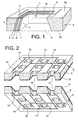
- FIG. 1 represents a hole 1 with a geometry according to the present invention, a hole on the walls of which layers constituting an elementary cell are arranged during a step of the method of the invention.
- the hole 1 has a truncated pyramidal shape, more precisely with a square base and opens on opposite sides of the opposite faces 9a, 9b of a support 9 by a first orifice section referenced 1a and a second orifice section 1b, the surface of the first orifice section being, in this particular case, smaller than any arbitrary sections of the hole taken in a plane parallel to the aforementioned opposite faces and said hole having a lateral surface 1c.
- This hole has a sloped inner profile, which contributes to facilitate the step of producing the elementary cells, with respect to a hole whose walls would be perpendicular to the opposite faces of said support.
- the support provided with holes, in which elementary cells are formed constitutes a basic module, said module being intended to be assembled with at least one other module, so as to form at least one cavity level.
- FIG. 2 makes it possible to understand, according to one particular embodiment of the invention, the manner in which two basic modules, referenced 9 ', are assembled.
- this figure shows two substantially identical parallelepiped-shaped supports 9, provided with three rows of holes 10, of truncated pyramidal shape with a square base.
- Each hole 10 constitutes an elementary cell as previously described in FIG. 1, the different cells being electrically connected in series by a network.
- electrical connections 11,12 (respectively anodic and cathodic) in the form of tracks, so as to add the active surfaces of each elementary cell.
- the electrical connection between the different cells can be done in parallel.
- the reagent distribution network is not shown in this figure.
- the faces devoid of networks of electrical connections and reagent distribution two basic modules are covered with a binding layer 13 impervious to reagents.
- This link layer may be, for example; the membrane layer, used in particular for its reagent-sealing properties but also a layer having adhesive properties, said layer consisting for example of a material selected from a group consisting of epoxides, polyimides, silicones acrylic polymers.
- the assembly of two basic modules must be done in such a way that the holes of a basic module are adjusted opposite the holes of the adjacent base module or modules, so as to add the active surface of the base module. a hole of a module with the active surface of the hole of the adjacent module or modules.
- the basic modules to be assembled are, for example, positioned using a double-sided positioning machine with level of each module, a positioning cross system.
- the assembly is finalized by a step of joining the two basic modules, said step being able to take place according to different techniques.
- the joining can also be done by gluing.
- bonding techniques that may be envisaged, there may be mentioned bonding by molecular adhesion, adhesive bonding or welding of polymeric materials of the same kind after treatment around the glass transition temperature.
- the bonding layer is of identical constitution to the membrane layer, said membrane being of polymeric material, the bonding can be obtained by heat treatment of the layer at a temperature greater than or equal to the glass transition temperature of the polymer .
- the assembly resulting from this step of joining two basic modules, constitutes, according to the terminology of the invention, a level of cavities.
- such an assembly advantageously comprises, where appropriate, a step of masking the networks of electrical connections and distribution of reagents of the faces, intended to be contiguous, by a waterproof and insulating layer, a planarization step of the the faces provided with said networks followed by a step of setting up a bonding layer on at least one of the faces, intended to be contiguous and finally a step of securing the faces in question.
- the masking step consists, as its name suggests, in masking the electrical connection networks and the reagent distribution networks, in order to avoid the problems of short circuits when joining the two faces and the problems leaking reagents.
- This step is, for example, provided by the establishment of a waterproof and insulating layer.
- the planarization step consists in flattening the surfaces of the faces provided with networks intended for joining, for example by placing a planarizing layer or by a mechanical process such as polishing. This planarization step is necessary, to avoid any problem of discontinuity of surfaces during assembly of the modules.
- a particularly advantageous embodiment of the invention consists in carrying out the step of masking, planarizing and setting up a bonding layer by placing a single layer, which is, for example, a layer of constitution identical to the membrane, constituted for example by Nafion ® , or a layer of inorganic material such as a material selected from silicon oxide, silicon nitride or a multilayer consisting of these different materials.
- FIG 3 illustrates a sectional view of a stack resulting from the joining of two levels of cavities, obtained according to a particular embodiment of the invention.
- the holes 14 made at these different basic modules are of frustoconical shape, which corresponds to a hole geometry according to the present invention.
- each hole 14 On the lateral surface 14a of each hole 14 there are superposed layers, namely a first electrode layer 15, a membrane layer 16 and a second electrode layer 17.
- the layer 18 is identical in constitution to the membrane layer 16. Note that according to this particular embodiment, the assembly of two base modules 19, to access a level of cavities 20, consists of assembling two faces without networks.
- the single layer 21 is of identical constitution to the membrane layer 16.
- the cells of the two cavity levels are electrically connected to one another via electrical connection networks 22, 23 in series.
- the assembly of two basic modules, to form a level of cavities, as well as two levels of cavities can be considered in different ways.
- each of the basic modules comprises a plurality of holes, said holes having a frustoconical shape.
- each of the two cavity levels 25 results from the assembly of two base modules 24, in particular by facing the holes 26 by their bases 27 (represented in solid lines in the figure), said levels being then assembled by facing the cavities thus constituted by their vertices 28 (shown in solid lines in the figure).
- each of the cavities 25 levels results from the assembly of two modules 24 in particular by facing the holes 26 by their vertices 28, said levels then being assembled in particular by facing the cavities thus constituted by their bases. 27.
- each of the cavities 25 levels results from the assembly of two base modules 24 by facing the holes 26 base 27 against the apex 28, said levels being then assembled by facing the cavities thus formed.
- the objective is to develop an active surface of 350 cm 2 for an apparent surface of 25 cm 2 and an energy of 10 Wh.
- the anode and cathode connection networks are made on one of the faces of the support, by photolithography techniques with photosensitive resins and dry photosensitive films, and the distribution network of the reagents by etching the channels. At the end of these steps, a basic module is obtained.
- the assembly of two basic modules is carried out via NAFION ® layers, glued after heat treatment at a temperature above the glass transition temperature. In this way, a level of cavities is obtained.
- the assembly of several cavity levels is provided by a silica layer and finalized by a molecular bonding step.
Landscapes
- Life Sciences & Earth Sciences (AREA)
- Engineering & Computer Science (AREA)
- Manufacturing & Machinery (AREA)
- Sustainable Development (AREA)
- Sustainable Energy (AREA)
- Chemical & Material Sciences (AREA)
- Chemical Kinetics & Catalysis (AREA)
- Electrochemistry (AREA)
- General Chemical & Material Sciences (AREA)
- Fuel Cell (AREA)
- Inert Electrodes (AREA)
Claims (20)
- Verfahren zur Herstellung einer Brennstoffzelle, wobei diese Brennstoffzelle eine Gruppe elektrisch miteinander verbundener Elementarzellen umfasst, jede Elementarzelle wenigstens drei Schichten aufweist, nämlich eine erste Elektrodenschicht, eine zweite Elektrodenschicht und eine dazwischen befindliche Membranschicht, und das genannte Verfahren sukzessive die folgenden Schritte umfasst:- einen Schritt zur Realisierung einer Vielzahl von Löchern (1, 10) in wenigstens zwei Trägern (9), wobei jedes Loch auf beiden der entgegengesetzten Seiten (9a, 9b) jedes Trägers mündet, mit einem ersten Öffnungsquerschnitt (1a) und einem zweiten Öffnungsquerschnitt (1b), und jedes Loch eine Seitenfläche (1 c) aufweist;- einen Schritt zur Realisierung von Elementarzellen auf der Seitenfläche (1c) von jedem der genannten Löcher;- einen Schritt zur Realisierung - auf wenigstens einer der genannten entgegengesetzten Seiten jedes Trägers - eines elektrischen Verbindungsnetzes (11, 12) und eines Reagenzienverteilungsnetzes, wobei die genannten Netze die Elementarzellen miteinander verbinden und das aus einem Träger, den Elementarzellen und den genannten Netzen bestehende Ganze einen Basismodul (9') bildet;- einen Schritt, in dem zwei Basismodule (9') so zusammengebaut werden, dass die Elementarzellen jedes Basismoduls den Elementarzellen des (der) angrenzenden Basismoduls (Basismodule) gegenüberstehen;dabei ist das genannte Verfahren dadurch gekennzeichnet, dass während des Schritts zur Realisierung der Vielzahl von Löchern jedes Loch so realisiert wird, dass wenigstens einer, d.h. der erste oder der zweite der genannten Öffnungsquerschnitte (1a, 1b) jedes Lochs eine Fläche aufweist, die kleiner ist als die Fläche von wenigstens einem Querschnitt des genannten Lochs in einer zu den genannten entgegengesetzten Seiten parallelen Ebene, und dadurch, dass für jedes Loch der erste oder der zweite Öffnungsquerschnitt eine Fläche aufweist, die kleiner ist als die Fläche des anderen Öffnungsquerschnitts.
- Verfahren zur Herstellung einer Brennstoffzelle nach Anspruch 1, dadurch gekennzeichnet, dass die Löcher im Wesentlichen kegelstumpfartig sind.
- Verfahren zur Herstellung einer Brennstoffzelle nach Anspruch 1, dadurch gekennzeichnet, dass die Löcher im Wesentlichen pyramidenstumpfförmig sind.
- Verfahren zur Herstellung einer Brennstoffzelle nach einem der Ansprüche 1 bis 3, dadurch gekennzeichnet, dass jedes in jedem Träger realisierte Loch einen ersten Öffnungsquerschnitt und einen zweiten Öffnungsquerschnitt mit kleineren Flächen als der Seitenfläche des genannten Lochs aufweist.
- Verfahren zur Herstellung einer Brennstoffzelle nach einem der Ansprüche 1 bis 4, dadurch gekennzeichnet, dass die Löcher in jedem Träger durch Ätzung realisiert werden.
- Verfahren zur Herstellung einer Brennstoffzelle nach einem der Ansprüche 1 bis 4, dadurch gekennzeichnet, dass die Löcher in jedem Träger durch Laserablation realisiert werden.
- Verfahren zur Herstellung einer Brennstoffzelle nach einem der vorangehenden Ansprüche, dadurch gekennzeichnet, dass der Träger durch ein aus einer Gruppe ausgewähltes Material gebildet wird, die Silicium wie etwa das poröse Silicium, Graphit, Keramiken und Polymere umfasst.
- Verfahren zur Herstellung einer Brennstoffzelle nach einem der vorangehenden Ansprüche, dadurch gekennzeichnet, dass die Realisierung der Elementarzellen durch sukzessive Abscheidungen auf der Seitenfläche jedes der genannten Löcher erfolgt, um die erste Elektrodenschicht, die Membranschicht und die zweite Elektrodenschicht auszubilden.
- Verfahren zur Herstellung einer Brennstoffzelle nach Anspruch 8, dadurch gekennzeichnet, dass die Realisierung der Elementarzellen außerdem das Abscheiden von Stromkollektoren in Höhe jeder Elektrodenschicht umfasst.
- Verfahren zur Herstellung einer Brennstoffzelle nach einem der Ansprüche 1 bis 9, dadurch gekennzeichnet, dass der Zusammenbau von zwei Basismodulen, bei dem zwei sich gegenüberstehende Seiten ohne die in Anspruch 1 definierten Netze zusammengebaut werden, die folgenden Schritte umfasst:- einen Schritt zur Abscheidung einer Verbindungsschicht (13) auf wenigstens einer der genannten netzlosen Seiten; und- einen Schritt zur Vereinigung der Basismodule mittels der genannten Seiten.
- Verfahren zur Herstellung einer Brennstoffzelle nach einem der Ansprüche 1 bis 9, dadurch gekennzeichnet, dass der Zusammenbau von wenigstens zwei Basismodulen mit sich gegenüberstehende Seiten, von denen wenigstens eine ein elektrisches Verbindungsnetz und/oder ein Reagenzienverteilungsnetz umfasst, die folgenden Schritte umfasst:- einen Schritt zur Maskierung der mit dem (den) genannten Netz(en) versehenen Seite(n) mit einer dichten und isolierenden Schicht;- einen Schritt zur Planarisierung der mit dem (den) genannten Netz(en) versehenen Seite(n);- einen Schritt zur Abscheidung einer Verbindungsschicht auf wenigstens einer der zusammenzufügenden Seiten;- einen Schritt zur Vereinigung der genannten zusammenzufügenden Seiten der genannten Basismodule.
- Herstellungsverfahren nach Anspruch 10 oder 11, dadurch gekennzeichnet, dass die Verbindungsschicht (13) eine Schicht mit derselben Konstitution bzw. Zusammensetzung wie die Membranschicht ist, oder eine Schicht aus einem Material ist, das aus der Gruppe ausgewählt wird, die das Siliciumoxid oder das Siliciumnitrid umfasst.
- Verfahren zur Herstellung einer Brennstoffzelle nach Anspruch 10 oder 11, dadurch gekennzeichnet, dass die Verbindungsschicht einem Adhäsiv entspricht, das ausgewählt wird unter den Epoxiden, den Polyimiden, den Siliconen, den Acrylpolymeren.
- Verfahren zur Herstellung einer Brennstoffzelle nach einem der Ansprüche 10 bis 13, dadurch gekennzeichnet, dass der Vereinigungsschritt eine Klemmung umfasst.
- Verfahren zur Herstellung einer Brennstoffzelle nach einem der Ansprüche 10 bis 13, dadurch gekennzeichnet, dass der Vereinigungsschritt eine molekulare Adhäsion umfasst.
- Verfahren zur Herstellung einer Brennstoffzelle nach einem der Ansprüche 10 bis 13, dadurch gekennzeichnet, dass der Vereinigungsschritt eine Klebung umfasst.
- Verfahren zur Herstellung einer Brennstoffzelle nach Anspruch 11, dadurch gekennzeichnet, dass der Maskierungsschritt, der Planarisierungsschritt und der Abscheidungsschritt der Verbindungsschicht simultan realisiert werden, durch das Abscheiden einer einzigen Schicht.
- Verfahren zur Herstellung einer Brennstoffzelle nach Anspruch 17, dadurch gekennzeichnet, dass die einzige Schicht die gleiche Konstitution bzw. Zusammensetzung wie die Membranschicht hat.
- Verfahren zur Herstellung einer Brennstoffzelle nach Anspruch 17, dadurch gekennzeichnet, dass die einzige Schicht aus einem Material ist, das ausgewählt wird aus der Gruppe, die Siliciumoxid und Siliciumnitrid umfasst.
- Brennstoffzelle, umfassend:- wenigstens zwei Träger (9) mit einer Vielzahl von Löchern (1, 10), wobei jedes Loch auf beiden der entgegengesetzten Seiten (9a, 9b) jedes Trägers mündet, mit einem ersten Öffnungsquerschnitt (1a) und einem zweiten Öffnungsquerschnitt (1b), und jedes Loch eine Seitenfläche (1c) aufweist;- Elementarzellen, realisiert auf der Seitenfläche (1c) von jedem der genannten Löcher;- auf wenigstens einer der genannten entgegengesetzten Seiten jedes Trägers ein elektrisches Verbindungsnetz (11, 12) und ein Reagenzienverteilungsnetz, wobei die genannten Netze die Elementarzellen miteinander verbinden und das aus einem Träger, den Elementarzellen und den genannten Netzen bestehende Ganze einen Basismodul bildet, und wenigstens zwei Basismodule so zusammengebaut werden, dass die Elementarzellen jedes Basismoduls den Elementarzellen des (der) angrenzenden Basismoduls (Basismodule) gegenüberstehen;dadurch gekennzeichnet, dass jedes Loch so realisiert wird, dass wenigstens einer, d.h. der erste oder der zweite der genannten Öffnungsquerschnitte (1a, 1b) jedes Lochs eine Fläche aufweist, die kleiner ist als die Fläche von wenigstens einem Querschnitt des genannten Lochs in einer zu den genannten entgegengesetzten Seiten parallelen Ebene, und dadurch, dass für jedes Loch der erste oder der zweite Öffnungsquerschnitt eine Fläche aufweist, die kleiner ist als die Fläche des anderen Öffnungsquerschnitts.
Applications Claiming Priority (3)
| Application Number | Priority Date | Filing Date | Title |
|---|---|---|---|
| FR0114841 | 2001-11-16 | ||
| FR0114841A FR2832549B1 (fr) | 2001-11-16 | 2001-11-16 | Pile a combustible a surface active importante et a volume reduit et son procede de fabrication |
| PCT/FR2002/003924 WO2003043117A2 (fr) | 2001-11-16 | 2002-11-15 | Procede de fabrication d'une pile a combustible a surface active importante et a volume reduit |
Publications (2)
| Publication Number | Publication Date |
|---|---|
| EP1456902A2 EP1456902A2 (de) | 2004-09-15 |
| EP1456902B1 true EP1456902B1 (de) | 2007-07-18 |
Family
ID=8869469
Family Applications (1)
| Application Number | Title | Priority Date | Filing Date |
|---|---|---|---|
| EP02803056A Expired - Lifetime EP1456902B1 (de) | 2001-11-16 | 2002-11-15 | Brennstoffzelle und verfahren zur herstellung einer solchen mit grosser aktiver oberfläche und mit verringertem volumen |
Country Status (9)
| Country | Link |
|---|---|
| US (1) | US7270686B2 (de) |
| EP (1) | EP1456902B1 (de) |
| JP (1) | JP4748937B2 (de) |
| CN (1) | CN100487968C (de) |
| AT (1) | ATE367659T1 (de) |
| DE (1) | DE60221281T2 (de) |
| ES (1) | ES2289179T3 (de) |
| FR (1) | FR2832549B1 (de) |
| WO (1) | WO2003043117A2 (de) |
Families Citing this family (17)
| Publication number | Priority date | Publication date | Assignee | Title |
|---|---|---|---|---|
| GB0323224D0 (en) * | 2003-10-03 | 2003-11-05 | Rolls Royce Plc | A module for a fuel cell stack |
| US7645537B2 (en) | 2003-10-15 | 2010-01-12 | Hewlett-Packard Development Company, L.P. | Multi-cell fuel cell layer and system |
| US7521145B2 (en) * | 2003-10-16 | 2009-04-21 | Wistron Corp. | Fuel cells for use in portable devices |
| JP2009502011A (ja) * | 2005-07-15 | 2009-01-22 | シンベット・コーポレイション | 軟質および硬質電解質層付き薄膜電池および方法 |
| US7776478B2 (en) | 2005-07-15 | 2010-08-17 | Cymbet Corporation | Thin-film batteries with polymer and LiPON electrolyte layers and method |
| US7871734B2 (en) * | 2005-08-23 | 2011-01-18 | Massachusetts Institute Of Technology | Micro fuel cell |
| FR2894720B1 (fr) * | 2005-12-09 | 2010-12-10 | Commissariat Energie Atomique | Pile a combustible avec collecteurs de courant integres a l'electrolyte solide et procede de fabrication d'une telle pile a combustible. |
| KR100702031B1 (ko) * | 2006-02-22 | 2007-03-30 | 삼성전자주식회사 | 배터리 결합 반도체소자 |
| JP2007323938A (ja) * | 2006-05-31 | 2007-12-13 | Sanyo Electric Co Ltd | 燃料電池および燃料電池モジュール |
| US20080061027A1 (en) * | 2006-09-12 | 2008-03-13 | Mangat Pawitter S | Method for forming a micro fuel cell |
| JP2010015974A (ja) * | 2008-03-28 | 2010-01-21 | Fuji Heavy Ind Ltd | 電極の製造方法、蓄電デバイス、および中間積層材 |
| US11996517B2 (en) | 2011-06-29 | 2024-05-28 | Space Charge, LLC | Electrochemical energy storage devices |
| US10658705B2 (en) | 2018-03-07 | 2020-05-19 | Space Charge, LLC | Thin-film solid-state energy storage devices |
| US9853325B2 (en) | 2011-06-29 | 2017-12-26 | Space Charge, LLC | Rugged, gel-free, lithium-free, high energy density solid-state electrochemical energy storage devices |
| US11527774B2 (en) | 2011-06-29 | 2022-12-13 | Space Charge, LLC | Electrochemical energy storage devices |
| US10601074B2 (en) | 2011-06-29 | 2020-03-24 | Space Charge, LLC | Rugged, gel-free, lithium-free, high energy density solid-state electrochemical energy storage devices |
| GB2549934A (en) | 2016-04-28 | 2017-11-08 | Reinhausen Maschf Scheubeck | Junction temperature and current sensing |
Family Cites Families (18)
| Publication number | Priority date | Publication date | Assignee | Title |
|---|---|---|---|---|
| DE2614728A1 (de) * | 1976-04-06 | 1977-10-20 | Bbc Brown Boveri & Cie | Bauteil fuer eine elektrochemische batterie |
| JPS63138667A (ja) * | 1986-11-29 | 1988-06-10 | Mitsubishi Heavy Ind Ltd | 固体電解質型燃料電池 |
| JPH05174852A (ja) * | 1991-12-17 | 1993-07-13 | Yoshida Kogyo Kk <Ykk> | 固体電解質燃料電池用導電性接続部材 |
| US5445903A (en) * | 1993-09-09 | 1995-08-29 | Technology Management, Inc. | Electrochemical apparatus |
| US5631099A (en) | 1995-09-21 | 1997-05-20 | Hockaday; Robert G. | Surface replica fuel cell |
| US6001500A (en) | 1996-06-05 | 1999-12-14 | Southwest Res Inst | Cylindrical proton exchange membrane fuel cells and methods of making same |
| US6007932A (en) | 1996-10-16 | 1999-12-28 | Gore Enterprise Holdings, Inc. | Tubular fuel cell assembly and method of manufacture |
| US5759712A (en) | 1997-01-06 | 1998-06-02 | Hockaday; Robert G. | Surface replica fuel cell for micro fuel cell electrical power pack |
| US6080501A (en) | 1998-06-29 | 2000-06-27 | Motorola, Inc. | Fuel cell with integral fuel storage |
| US6638654B2 (en) * | 1999-02-01 | 2003-10-28 | The Regents Of The University Of California | MEMS-based thin-film fuel cells |
| CA2370899A1 (en) * | 1999-05-06 | 2000-11-16 | Sandia Corporation | Fuel cell and membrane |
| US6312846B1 (en) * | 1999-11-24 | 2001-11-06 | Integrated Fuel Cell Technologies, Inc. | Fuel cell and power chip technology |
| US6528199B1 (en) * | 2000-04-14 | 2003-03-04 | Graftech Inc. | Graphite article useful as an electrode for an electrochemical fuel cell |
| US7008718B2 (en) * | 2000-05-08 | 2006-03-07 | Honda Giken Kogyo Kabushiki Kaisha | Fuel cell assembly |
| FR2814857B1 (fr) * | 2000-10-04 | 2004-11-26 | Sagem | Micropiles a combustible notamment utilisees dans les dispositifs electroniques portables, dans les equipements automobiles et dans les dispositifs de telecommunication |
| US6605379B1 (en) * | 2000-11-03 | 2003-08-12 | Grafttech Inc. | Hydrophobic fuel cell electrode |
| JP2002164062A (ja) * | 2000-11-28 | 2002-06-07 | Araco Corp | 燃料電池用セパレータおよびその製造方法 |
| US20030096146A1 (en) * | 2001-03-30 | 2003-05-22 | Foster Ronald B. | Planar substrate-based fuel cell Membrane Electrode Assembly and integrated circuitry |
-
2001
- 2001-11-16 FR FR0114841A patent/FR2832549B1/fr not_active Expired - Fee Related
-
2002
- 2002-11-15 US US10/495,251 patent/US7270686B2/en not_active Expired - Fee Related
- 2002-11-15 WO PCT/FR2002/003924 patent/WO2003043117A2/fr not_active Ceased
- 2002-11-15 ES ES02803056T patent/ES2289179T3/es not_active Expired - Lifetime
- 2002-11-15 AT AT02803056T patent/ATE367659T1/de not_active IP Right Cessation
- 2002-11-15 JP JP2003544838A patent/JP4748937B2/ja not_active Expired - Fee Related
- 2002-11-15 DE DE60221281T patent/DE60221281T2/de not_active Expired - Lifetime
- 2002-11-15 CN CNB028272161A patent/CN100487968C/zh not_active Expired - Fee Related
- 2002-11-15 EP EP02803056A patent/EP1456902B1/de not_active Expired - Lifetime
Non-Patent Citations (1)
| Title |
|---|
| None * |
Also Published As
| Publication number | Publication date |
|---|---|
| ATE367659T1 (de) | 2007-08-15 |
| FR2832549A1 (fr) | 2003-05-23 |
| CN1615557A (zh) | 2005-05-11 |
| WO2003043117A2 (fr) | 2003-05-22 |
| ES2289179T3 (es) | 2008-02-01 |
| CN100487968C (zh) | 2009-05-13 |
| US7270686B2 (en) | 2007-09-18 |
| FR2832549B1 (fr) | 2004-05-28 |
| JP2005510019A (ja) | 2005-04-14 |
| EP1456902A2 (de) | 2004-09-15 |
| DE60221281D1 (de) | 2007-08-30 |
| WO2003043117A3 (fr) | 2004-02-19 |
| JP4748937B2 (ja) | 2011-08-17 |
| DE60221281T2 (de) | 2008-04-10 |
| US20050019635A1 (en) | 2005-01-27 |
Similar Documents
| Publication | Publication Date | Title |
|---|---|---|
| EP1456902B1 (de) | Brennstoffzelle und verfahren zur herstellung einer solchen mit grosser aktiver oberfläche und mit verringertem volumen | |
| EP2061114B1 (de) | Brennstoffzelle, bestehend aus mehreren Elementarzellen, die durch Serienschaltung mit den Stromkollektoren miteinander verbunden sind | |
| WO2002054522A1 (fr) | Procede de fabrication d'un assemblage d'elements de base pour un etage de pile a combustible | |
| EP3482866B1 (de) | Verfahren, das einen laser zum verschweissen von zwei metallmaterialen oder zum sintern von pulver(n) verwendet, anwendung zur herstellung von bipolarplatten für pemfc-brennstoffzellen | |
| EP1915797A1 (de) | Polymerverbundmembran mit ionen-/elektronenleitfähigkeit, herstellungsverfahren dafür und kern einer planaren brennstoffzelle mit dieser membran | |
| EP1645006B1 (de) | Brennstoffzelle, in dem ein fluid im wesentlichen parallel zu der elektrolytischen membran zirkuliert und verfahren zur herstellung einer solchen brennstoffzelle | |
| FR2838870A1 (fr) | Element de base de pile a combustible limitant la traversee de l'electrolyte par le methanol | |
| FR2919760A1 (fr) | Procede de fabrication d'une pile a combustible sur un support poreux | |
| EP1282185A2 (de) | Verfahren zur Herstellung einer Brennstoffzelle mit zylindrischer Geometrie | |
| EP1645004A2 (de) | Brennstoffzelle mit in den stapel aus elektrode/membran/elektrode integrierten stromkollektoren | |
| FR2846797A1 (fr) | Module de base monobloc et a relief de pile a combustible miniature et son procede de fabrication | |
| EP2165381B1 (de) | Undurchlässiges poröses substrat für planare brennstoffzellen und integrierte verpackung dafür | |
| EP1982380B1 (de) | Integrierte brennstoffzelle und herstellungsverfahren | |
| FR2963483A1 (fr) | Pile a combustible comportant une pluralite de cellules elementaires connectees en serie et son procede de realisation | |
| EP1763100B1 (de) | Mikrobrennstoffzelle mit Verankerungselement verstärkte elektrolytische Membrane und Verfahren zu deren Herstellung | |
| WO2025012385A1 (fr) | Cellule électrochimique à électrode support structurée | |
| FR2894075A1 (fr) | Support de pile a combustible integree | |
| EP1532703A2 (de) | Miniatur-brennstoffzellenbasismodul mit mikrovolumen, die von einem von zwei reaktionsmitteln durchquert werden | |
| WO2007063257A1 (fr) | Pile a combustible integree empilable |
Legal Events
| Date | Code | Title | Description |
|---|---|---|---|
| PUAI | Public reference made under article 153(3) epc to a published international application that has entered the european phase |
Free format text: ORIGINAL CODE: 0009012 |
|
| 17P | Request for examination filed |
Effective date: 20040504 |
|
| AK | Designated contracting states |
Kind code of ref document: A2 Designated state(s): AT BE BG CH CY CZ DE DK EE ES FI FR GB GR IE IT LI LU MC NL PT SE SK TR |
|
| AX | Request for extension of the european patent |
Extension state: AL LT LV MK RO SI |
|
| RAP1 | Party data changed (applicant data changed or rights of an application transferred) |
Owner name: COMMISSARIAT A L'ENERGIE ATOMIQUE |
|
| RTI1 | Title (correction) |
Free format text: FUEL CELL AND METHOD FOR MAKING SUCH A CELL WITH LARGE ACTIVE SURFACE AND REDUCED VOLUME |
|
| GRAP | Despatch of communication of intention to grant a patent |
Free format text: ORIGINAL CODE: EPIDOSNIGR1 |
|
| GRAS | Grant fee paid |
Free format text: ORIGINAL CODE: EPIDOSNIGR3 |
|
| GRAA | (expected) grant |
Free format text: ORIGINAL CODE: 0009210 |
|
| AK | Designated contracting states |
Kind code of ref document: B1 Designated state(s): AT BE BG CH CY CZ DE DK EE ES FI FR GB GR IE IT LI LU MC NL PT SE SK TR |
|
| REG | Reference to a national code |
Ref country code: GB Ref legal event code: FG4D Free format text: NOT ENGLISH |
|
| REG | Reference to a national code |
Ref country code: CH Ref legal event code: EP |
|
| REF | Corresponds to: |
Ref document number: 60221281 Country of ref document: DE Date of ref document: 20070830 Kind code of ref document: P |
|
| REG | Reference to a national code |
Ref country code: IE Ref legal event code: FG4D Free format text: LANGUAGE OF EP DOCUMENT: FRENCH |
|
| GBT | Gb: translation of ep patent filed (gb section 77(6)(a)/1977) |
Effective date: 20071003 |
|
| PG25 | Lapsed in a contracting state [announced via postgrant information from national office to epo] |
Ref country code: BG Free format text: LAPSE BECAUSE OF FAILURE TO SUBMIT A TRANSLATION OF THE DESCRIPTION OR TO PAY THE FEE WITHIN THE PRESCRIBED TIME-LIMIT Effective date: 20071018 Ref country code: PT Free format text: LAPSE BECAUSE OF FAILURE TO SUBMIT A TRANSLATION OF THE DESCRIPTION OR TO PAY THE FEE WITHIN THE PRESCRIBED TIME-LIMIT Effective date: 20071218 |
|
| REG | Reference to a national code |
Ref country code: ES Ref legal event code: FG2A Ref document number: 2289179 Country of ref document: ES Kind code of ref document: T3 |
|
| PG25 | Lapsed in a contracting state [announced via postgrant information from national office to epo] |
Ref country code: AT Free format text: LAPSE BECAUSE OF FAILURE TO SUBMIT A TRANSLATION OF THE DESCRIPTION OR TO PAY THE FEE WITHIN THE PRESCRIBED TIME-LIMIT Effective date: 20070718 |
|
| REG | Reference to a national code |
Ref country code: IE Ref legal event code: FD4D |
|
| PG25 | Lapsed in a contracting state [announced via postgrant information from national office to epo] |
Ref country code: DK Free format text: LAPSE BECAUSE OF FAILURE TO SUBMIT A TRANSLATION OF THE DESCRIPTION OR TO PAY THE FEE WITHIN THE PRESCRIBED TIME-LIMIT Effective date: 20070718 Ref country code: GR Free format text: LAPSE BECAUSE OF FAILURE TO SUBMIT A TRANSLATION OF THE DESCRIPTION OR TO PAY THE FEE WITHIN THE PRESCRIBED TIME-LIMIT Effective date: 20071019 |
|
| PLBE | No opposition filed within time limit |
Free format text: ORIGINAL CODE: 0009261 |
|
| STAA | Information on the status of an ep patent application or granted ep patent |
Free format text: STATUS: NO OPPOSITION FILED WITHIN TIME LIMIT |
|
| PG25 | Lapsed in a contracting state [announced via postgrant information from national office to epo] |
Ref country code: CZ Free format text: LAPSE BECAUSE OF FAILURE TO SUBMIT A TRANSLATION OF THE DESCRIPTION OR TO PAY THE FEE WITHIN THE PRESCRIBED TIME-LIMIT Effective date: 20070718 Ref country code: IE Free format text: LAPSE BECAUSE OF FAILURE TO SUBMIT A TRANSLATION OF THE DESCRIPTION OR TO PAY THE FEE WITHIN THE PRESCRIBED TIME-LIMIT Effective date: 20070718 Ref country code: SK Free format text: LAPSE BECAUSE OF FAILURE TO SUBMIT A TRANSLATION OF THE DESCRIPTION OR TO PAY THE FEE WITHIN THE PRESCRIBED TIME-LIMIT Effective date: 20070718 |
|
| BERE | Be: lapsed |
Owner name: COMMISSARIAT A L'ENERGIE ATOMIQUE Effective date: 20071130 |
|
| 26N | No opposition filed |
Effective date: 20080421 |
|
| PG25 | Lapsed in a contracting state [announced via postgrant information from national office to epo] |
Ref country code: SE Free format text: LAPSE BECAUSE OF FAILURE TO SUBMIT A TRANSLATION OF THE DESCRIPTION OR TO PAY THE FEE WITHIN THE PRESCRIBED TIME-LIMIT Effective date: 20071018 Ref country code: MC Free format text: LAPSE BECAUSE OF NON-PAYMENT OF DUE FEES Effective date: 20071130 |
|
| PG25 | Lapsed in a contracting state [announced via postgrant information from national office to epo] |
Ref country code: CH Free format text: LAPSE BECAUSE OF NON-PAYMENT OF DUE FEES Effective date: 20071130 Ref country code: LI Free format text: LAPSE BECAUSE OF NON-PAYMENT OF DUE FEES Effective date: 20071130 |
|
| REG | Reference to a national code |
Ref country code: CH Ref legal event code: PL |
|
| PG25 | Lapsed in a contracting state [announced via postgrant information from national office to epo] |
Ref country code: BE Free format text: LAPSE BECAUSE OF NON-PAYMENT OF DUE FEES Effective date: 20071130 |
|
| PG25 | Lapsed in a contracting state [announced via postgrant information from national office to epo] |
Ref country code: EE Free format text: LAPSE BECAUSE OF FAILURE TO SUBMIT A TRANSLATION OF THE DESCRIPTION OR TO PAY THE FEE WITHIN THE PRESCRIBED TIME-LIMIT Effective date: 20070718 |
|
| PG25 | Lapsed in a contracting state [announced via postgrant information from national office to epo] |
Ref country code: CY Free format text: LAPSE BECAUSE OF FAILURE TO SUBMIT A TRANSLATION OF THE DESCRIPTION OR TO PAY THE FEE WITHIN THE PRESCRIBED TIME-LIMIT Effective date: 20070718 |
|
| PG25 | Lapsed in a contracting state [announced via postgrant information from national office to epo] |
Ref country code: LU Free format text: LAPSE BECAUSE OF NON-PAYMENT OF DUE FEES Effective date: 20071115 |
|
| PG25 | Lapsed in a contracting state [announced via postgrant information from national office to epo] |
Ref country code: TR Free format text: LAPSE BECAUSE OF FAILURE TO SUBMIT A TRANSLATION OF THE DESCRIPTION OR TO PAY THE FEE WITHIN THE PRESCRIBED TIME-LIMIT Effective date: 20070718 |
|
| PGFP | Annual fee paid to national office [announced via postgrant information from national office to epo] |
Ref country code: FI Payment date: 20121018 Year of fee payment: 11 |
|
| PGFP | Annual fee paid to national office [announced via postgrant information from national office to epo] |
Ref country code: NL Payment date: 20121016 Year of fee payment: 11 |
|
| REG | Reference to a national code |
Ref country code: NL Ref legal event code: V1 Effective date: 20140601 |
|
| PG25 | Lapsed in a contracting state [announced via postgrant information from national office to epo] |
Ref country code: NL Free format text: LAPSE BECAUSE OF NON-PAYMENT OF DUE FEES Effective date: 20140601 Ref country code: FI Free format text: LAPSE BECAUSE OF NON-PAYMENT OF DUE FEES Effective date: 20131115 |
|
| REG | Reference to a national code |
Ref country code: FR Ref legal event code: PLFP Year of fee payment: 14 |
|
| PGFP | Annual fee paid to national office [announced via postgrant information from national office to epo] |
Ref country code: IT Payment date: 20151118 Year of fee payment: 14 Ref country code: DE Payment date: 20151109 Year of fee payment: 14 Ref country code: GB Payment date: 20151116 Year of fee payment: 14 |
|
| PGFP | Annual fee paid to national office [announced via postgrant information from national office to epo] |
Ref country code: ES Payment date: 20151125 Year of fee payment: 14 Ref country code: FR Payment date: 20151130 Year of fee payment: 14 |
|
| REG | Reference to a national code |
Ref country code: DE Ref legal event code: R119 Ref document number: 60221281 Country of ref document: DE |
|
| GBPC | Gb: european patent ceased through non-payment of renewal fee |
Effective date: 20161115 |
|
| REG | Reference to a national code |
Ref country code: FR Ref legal event code: ST Effective date: 20170731 |
|
| PG25 | Lapsed in a contracting state [announced via postgrant information from national office to epo] |
Ref country code: IT Free format text: LAPSE BECAUSE OF NON-PAYMENT OF DUE FEES Effective date: 20161115 Ref country code: FR Free format text: LAPSE BECAUSE OF NON-PAYMENT OF DUE FEES Effective date: 20161130 |
|
| PG25 | Lapsed in a contracting state [announced via postgrant information from national office to epo] |
Ref country code: GB Free format text: LAPSE BECAUSE OF NON-PAYMENT OF DUE FEES Effective date: 20161115 Ref country code: DE Free format text: LAPSE BECAUSE OF NON-PAYMENT OF DUE FEES Effective date: 20170601 |
|
| PG25 | Lapsed in a contracting state [announced via postgrant information from national office to epo] |
Ref country code: ES Free format text: LAPSE BECAUSE OF NON-PAYMENT OF DUE FEES Effective date: 20161116 |
|
| REG | Reference to a national code |
Ref country code: ES Ref legal event code: FD2A Effective date: 20181119 |