EP1456979B1 - Compensateur de dispersion de mode de polarisation - Google Patents
Compensateur de dispersion de mode de polarisation Download PDFInfo
- Publication number
- EP1456979B1 EP1456979B1 EP02783475.3A EP02783475A EP1456979B1 EP 1456979 B1 EP1456979 B1 EP 1456979B1 EP 02783475 A EP02783475 A EP 02783475A EP 1456979 B1 EP1456979 B1 EP 1456979B1
- Authority
- EP
- European Patent Office
- Prior art keywords
- parameters
- accordance
- compensator
- computed
- optical
- Prior art date
- Legal status (The legal status is an assumption and is not a legal conclusion. Google has not performed a legal analysis and makes no representation as to the accuracy of the status listed.)
- Expired - Lifetime
Links
- 239000006185 dispersion Substances 0.000 title description 5
- 230000003287 optical effect Effects 0.000 claims description 48
- 238000000034 method Methods 0.000 claims description 28
- 230000010287 polarization Effects 0.000 claims description 23
- 239000013598 vector Substances 0.000 claims description 18
- 239000011159 matrix material Substances 0.000 claims description 11
- 239000013307 optical fiber Substances 0.000 claims description 9
- 239000000835 fiber Substances 0.000 claims description 7
- 230000003044 adaptive effect Effects 0.000 claims description 6
- 238000004891 communication Methods 0.000 claims description 5
- 230000009466 transformation Effects 0.000 claims description 2
- 230000005540 biological transmission Effects 0.000 description 4
- 230000009268 pathologic speech processing Effects 0.000 description 3
- 208000032207 progressive 1 supranuclear palsy Diseases 0.000 description 3
- 238000012546 transfer Methods 0.000 description 3
- 230000001934 delay Effects 0.000 description 2
- 230000000694 effects Effects 0.000 description 2
- 238000012512 characterization method Methods 0.000 description 1
- 230000001419 dependent effect Effects 0.000 description 1
- 238000013461 design Methods 0.000 description 1
- 238000010586 diagram Methods 0.000 description 1
- 238000012986 modification Methods 0.000 description 1
- 230000004048 modification Effects 0.000 description 1
- 238000010606 normalization Methods 0.000 description 1
Images

Classifications
-
- G—PHYSICS
- G02—OPTICS
- G02B—OPTICAL ELEMENTS, SYSTEMS OR APPARATUS
- G02B6/00—Light guides; Structural details of arrangements comprising light guides and other optical elements, e.g. couplings
- G02B6/24—Coupling light guides
- G02B6/26—Optical coupling means
- G02B6/27—Optical coupling means with polarisation selective and adjusting means
- G02B6/2726—Optical coupling means with polarisation selective and adjusting means in or on light guides, e.g. polarisation means assembled in a light guide
- G02B6/274—Optical coupling means with polarisation selective and adjusting means in or on light guides, e.g. polarisation means assembled in a light guide based on light guide birefringence, e.g. due to coupling between light guides
-
- G—PHYSICS
- G02—OPTICS
- G02B—OPTICAL ELEMENTS, SYSTEMS OR APPARATUS
- G02B6/00—Light guides; Structural details of arrangements comprising light guides and other optical elements, e.g. couplings
- G02B6/24—Coupling light guides
- G02B6/26—Optical coupling means
- G02B6/27—Optical coupling means with polarisation selective and adjusting means
- G02B6/2753—Optical coupling means with polarisation selective and adjusting means characterised by their function or use, i.e. of the complete device
- G02B6/278—Controlling polarisation mode dispersion [PMD], e.g. PMD compensation or emulation
-
- G—PHYSICS
- G02—OPTICS
- G02B—OPTICAL ELEMENTS, SYSTEMS OR APPARATUS
- G02B6/00—Light guides; Structural details of arrangements comprising light guides and other optical elements, e.g. couplings
- G02B6/24—Coupling light guides
- G02B6/26—Optical coupling means
- G02B6/28—Optical coupling means having data bus means, i.e. plural waveguides interconnected and providing an inherently bidirectional system by mixing and splitting signals
- G02B6/293—Optical coupling means having data bus means, i.e. plural waveguides interconnected and providing an inherently bidirectional system by mixing and splitting signals with wavelength selective means
- G02B6/29379—Optical coupling means having data bus means, i.e. plural waveguides interconnected and providing an inherently bidirectional system by mixing and splitting signals with wavelength selective means characterised by the function or use of the complete device
- G02B6/29395—Optical coupling means having data bus means, i.e. plural waveguides interconnected and providing an inherently bidirectional system by mixing and splitting signals with wavelength selective means characterised by the function or use of the complete device configurable, e.g. tunable or reconfigurable
-
- H—ELECTRICITY
- H04—ELECTRIC COMMUNICATION TECHNIQUE
- H04B—TRANSMISSION
- H04B10/00—Transmission systems employing electromagnetic waves other than radio-waves, e.g. infrared, visible or ultraviolet light, or employing corpuscular radiation, e.g. quantum communication
- H04B10/25—Arrangements specific to fibre transmission
- H04B10/2507—Arrangements specific to fibre transmission for the reduction or elimination of distortion or dispersion
- H04B10/2569—Arrangements specific to fibre transmission for the reduction or elimination of distortion or dispersion due to polarisation mode dispersion [PMD]
Definitions
- the present invention relates to methods of adaptive adjustment of PMD compensators in optical fiber communication systems.
- the present invention also relates to a compensator in accordance with said method.
- a method for the adaptive adjustment of a PMD compensator in optical fiber communication systems with the compensator comprising a cascade of adjustable optical devices over which passes an optical signal to be compensated comprising the steps of computing the Stokes parameters S0, S1, S2, S3 in a number Q of different frequencies of the signal output from the compensator, producing control signals for parameters of at least some of said adjustable optical devices so as to make virtually constant said Stokes parameters computed at the different frequencies.
- a PMD compensator in optical fiber communication systems applying the method and comprising a cascade of adjustable optical devices over which passes an optical signal to be compensated and an adjustment system which takes the components y 1 (t) and y 2 (t) on the two orthogonal polarizations at the compensator output with the adjustment system comprising a controller which on the basis of said components taken computes the Stokes parameters S 0 , S 1 , S 2 , S 3 in a number Q of different frequencies of the signal output from the compensator and which emits control signals for at least some of said adjustable optical devices so as to make virtually constant the Stokes parameters computed at the different frequencies.
- FIG 1 shows the structure of a PMD compensator designated as a whole by reference number 10.
- This structure consists of the cascade of some optical devices which receive the signal from the transmission fiber 11.
- the first optical device is a polarization controller 12 (PC) which allows modification of the optical signal polarization at its input.
- PC polarization controller
- PMF polarization maintaining fibers 13
- a PMF fiber is a fiber which introduces a predetermined differential unit delay (DGD) between the components of the optical signal on the two principal states of polarization (PSP) termed slow PSP and fast PSP.
- DDD differential unit delay
- the DGD delays at the frequency of the optical carrier introduced by the three PMFs are respectively ⁇ c , ⁇ c and (1- ⁇ ) ⁇ c with 0 ⁇ 1 and with ⁇ c and ⁇ which are design parameters.
- An optical rotator is a device which can change the polarization of the optical signal upon its input by an angle ⁇ i (the figure shows ⁇ i for the first rotator and ⁇ 2 for the second) on a maximum circle on the Poincarè sphere.
- An optical rotator is implemented in practice by means of a properly controlled PC.
- x 1 (t) and x 2 (t) designate the components on the two PSPs of the optical signal at the compensator input whereas similarly y 1 (t) and y 2 (t) are the components of the optical signal at the compensator output.
- the Jones transfer matrix of the PC is: h 1 h 2 - h 2 * h 1 * where h 1 e h 2 satisfy the condition
- 2 1 and are frequency independent.
- an optical rotator with rotation angle ⁇ i is characterized by the following Jones matrix: cos ⁇ i sin ⁇ i - sin ⁇ i cos ⁇ i
- the Jones transfer matrix of a PMF with DGD ⁇ i may be expressed as RDR -1 where D is defined as: D ⁇ e j ⁇ ⁇ ⁇ ⁇ i / 2 0 0 e - j ⁇ ⁇ ⁇ ⁇ i / 2 and R is a unitary rotation matrix accounting for the PSPs' orientation.
- This matrix R may be taken as the identity matrix I without loss of generality when the PSPs of all the PMFs are aligned.
- controller 15 is needed to produce optical device control signals of the compensator computed on the basis of the quantities sent to it by a controller pilot 16 termed controller driver (CD).
- CD controller driver
- the CD feeds the controller with the quantities needed to update the compensator optical device control parameters. As described below, these quantities will be extracted by the CD from the signals at the input and/or output of the compensator.
- the controller will operate following the criterion described below and will use one of the two algorithms described below.
- ⁇ (t n ) designates the value of the compensator parameters after the nth update.
- the criterion for adjusting the compensator parameters employs the so-called Stokes parameters. Computation of the Stokes parameters for an optical signal is well known to those skilled in the art and is not further described.
- the parameters ⁇ of the compensator are adjusted to make constant the Stokes parameters computed at different frequencies on the compensator output signal.
- the four Stokes parameters So, S 1 , S 2 e S 3 computed at the frequency f l are designated by: S 0 ⁇
- f f l ⁇ S 0 , l S 1 ⁇
- f f l ⁇ S 1 , l S 2 ⁇
- f f l ⁇ S 2 , l S 3 ⁇
- f f l ⁇ S 3 , l
- the Stokes parameters computed at the frequency fp are designated by S 0,p , S 1,p , S 2,p e S 3,p .
- a simplified version of (9) consists of an update by means of a constant norm vector and therefore an update which uses only the information on the direction of ⁇ G ( ⁇ ) .
- the update rule becomes.
- ⁇ ⁇ t n + 1 ⁇ t n ⁇ sign ⁇ G ⁇ ⁇
- ⁇ ⁇ t n
- sign (z) designates a vector with unitary components and of the same sign as the components or the vector z.
- the partial derivatives of the function with respect to the compensator control parameters are computed without knowledge of this relationship. Consequently if the control parameters are different from those assumed as an example and are for example some voltage or some other angle, we may similarly compute the partial derivative and update these different control parameters accordingly.
- the update rules can be expressed as a function of the signals on the two orthogonal polarizations at the compensator input and output.
- the PMD compensator shown in FIG 1 is equivalent to a two-dimensional transversal filter with four tapped delay lines (TDL) combining the signals on the two principal polarization states (PSP).
- TDL tapped delay lines
- FIG 2 This equivalent model is shown in FIG 2 where: c 1 ⁇ cos ⁇ 1 ⁇ cos ⁇ 2 ⁇ h 1 c 2 ⁇ - sin ⁇ 1 ⁇ sin ⁇ 2 ⁇ h 1 c 3 ⁇ - sin ⁇ 1 ⁇ cos ⁇ 2 ⁇ h 2 * c 4 ⁇ - cos ⁇ 1 ⁇ sin ⁇ 2 ⁇ h 2 * c 5 ⁇ cos ⁇ 1 ⁇ cos ⁇ 2 ⁇ h 2 c 6 ⁇ - sin ⁇ 1 ⁇ sin ⁇ 2 ⁇ h 2 c 7 ⁇ sin ⁇ 1 ⁇ cos ⁇ 2 ⁇ h 1 * c 8 ⁇ cos ⁇ 1 ⁇ sin ⁇ 2 ⁇ h 1 *
- ⁇ ⁇ t n
- control parameters are different from those taken as examples we will naturally have different relationships between these control parameters and the coefficients c i .
- the CD must receive the optical signals at the input and output of the compensator.
Landscapes
- Physics & Mathematics (AREA)
- General Physics & Mathematics (AREA)
- Optics & Photonics (AREA)
- Chemical & Material Sciences (AREA)
- Dispersion Chemistry (AREA)
- Electromagnetism (AREA)
- Engineering & Computer Science (AREA)
- Computer Networks & Wireless Communication (AREA)
- Signal Processing (AREA)
- Optical Communication System (AREA)
- Footwear And Its Accessory, Manufacturing Method And Apparatuses (AREA)
Claims (16)
- Procédé pour l'ajustement adaptatif d'un compensateur PMD (10) dans des systèmes de communication à fibre optique avec le compensateur comprenant une cascade de dispositifs optiques ajustables (12, 14) via lesquels passe un signal optique à compenser, le procédé étant caractérisé en ce qu'il comprend les étapes consistant à :- calculer informatiquement les paramètres de Stokes S0, S1, S2, S3 dans un nombre Q de fréquences différentes du signal de sortie de compensateur, et- produire des signaux de commande pour les paramètres d'au moins certains desdits dispositifs optiques ajustables (12, 14) de manière à rendre virtuellement constants lesdits paramètres de Stokes calculés informatiquement à des fréquences différentes.
- Procédé selon la revendication 1, comprenant les étapes consistant à calculer informatiquement des paramètres de Stokes dans des paires de fréquences fl et fp avec l,p=1,2,...,Q, obtenir à la lème et pème fréquences des fréquences Q les deux séries de paramètres de Stokes S0,1, S1,1, S2,1, S3,1 et S0,p, S1,p, S2,p, S3,p, calculer informatiquement une fonction de vecteur de chaque série de paramètres de Stokes et produire les signaux de commande d'une manière telle que lesdites fonctions de vecteurs des deux séries de paramètres soient virtuellement parallèles l'une à l'autre.
- Procédé selon la revendication 2, dans lequel lesdits vecteurs sont des vecteurs de norme unitaire avec des composants donnés par les paramètres de Stokes S1, S2, S3 normalisés aux paramètre de Stokes S0, c'est à dire :


- Procédé selon la revendication 3, dans lequel est définie la fonction :


- Procédé selon la revendication 4, dans lequel les dispositifs optiques comprennent un contrôleur de polarisation (12) avec angles contrôlables φ1, φ2 et deux rotateurs (14) avec angles de rotation contrôlables respectivement θ1 et θ2, et afin de minimiser la fonction G(θ), la mise à jour de φ1, φ2, θ1 et θ2 du compensateur observe les règles suivantes pour aller de la nème itération et à la n+1ème itération :


- Procédé selon la revendication 5, dans lequel les dérivées partielles de G(θ) pour θ=θ(tn) sont calculées informatiquement conformément aux étapes suivantes :- Etape 1 trouver la valeur de G[(tn)]=G[φ1(tn), φ2(tn), θ1(tn), θ2(tn)] à l' itération n ; pour ce faire, dans l'intervalle de temps (tn, tn+Tu/5) les paramètres de Stokes aux fréquences Q sont déduits et la valeur de la fonction G(θ) est calculée informatiquement,- Etape 2 trouver la dérivée partielle

 - Etape 3 trouver la dérivée partielle :
 - Etape 4 trouver la dérivée partielle :
 - Etape 5 trouver la dérivée partielle :

- Procédé selon la revendication 1, comprenant les étapes consistant à calculer informatiquement les paramètres de Stokes en paires de fréquences fl et fp avec l,p= 1,2, ..., Q, afin d'obtenir à la lème et pème fréquence des Q fréquences les deux séries de paramètres de Stokes S1,l, S2,l, S3,l, S1,p, S2,p, S3,p, en définissant la fonction :

avec
en en produisant lesdits signaux de commande afin de minimiser ladite fonction H(θ). - Procédé selon la revendication 7, dans lequel les dispositifs optiques comprennent un contrôleur de polarisation (12) avec des angles contrôlables φ1, φ2 et deux rotateurs (14) avec des angles de rotation contrôlables respectivement θ1 et θ2, et pour minimiser la fonction H(θ) la mise à jour de φ1, φ2, θ1 et θ2 du compensateur suit les règles suivantes pour passer de la nème itération à la n+1ème itération :

ou la règle simplifiée suivante :
avec ∇HLP (θ) égal au gradient de Hlp(θ) par rapport à θ□. - Procédé selon la revendication 1, dans lequel le compensateur PMD (10) est modélisé comme un filtre transversal en deux dimensions avec quatre lignes de retard à épaisseur décroissante combinant les signaux sur les deux principaux états de polarisation (PSP).
- Procédé selon la revendication, dans lequel le gradient ∇HLP(θ) par rapport à θ est calculé informatiquement comme :
 - où y1,l(t), Y2,l(t) et Y1,p(t), y2,p(t) sont respectivement les composants y1(t) e y2(t) sur les deux polarisations orthogonales du signal de sortie de compensateur filtré respectivement à travers un filtre à bande étroite centré sur la fréquence fl et fp ; et- al(t) et bl(t) sont les vecteurs :
avec x1,l(t) et x2,l(t) qui sont respectivement des signaux x1(t) et x2(t) sur les deux polarisations orthogonales du signal d'entrée de compensateur filtré avec un filtre à bande étroite centré sur la fréquence f1 (similairement al(t) et bl(t) pour y1,p(t) et y2,p(t)) avec la fréquence fl), et- J est la matrice Jacobienne sur la transformation
c=c(θ) définie comme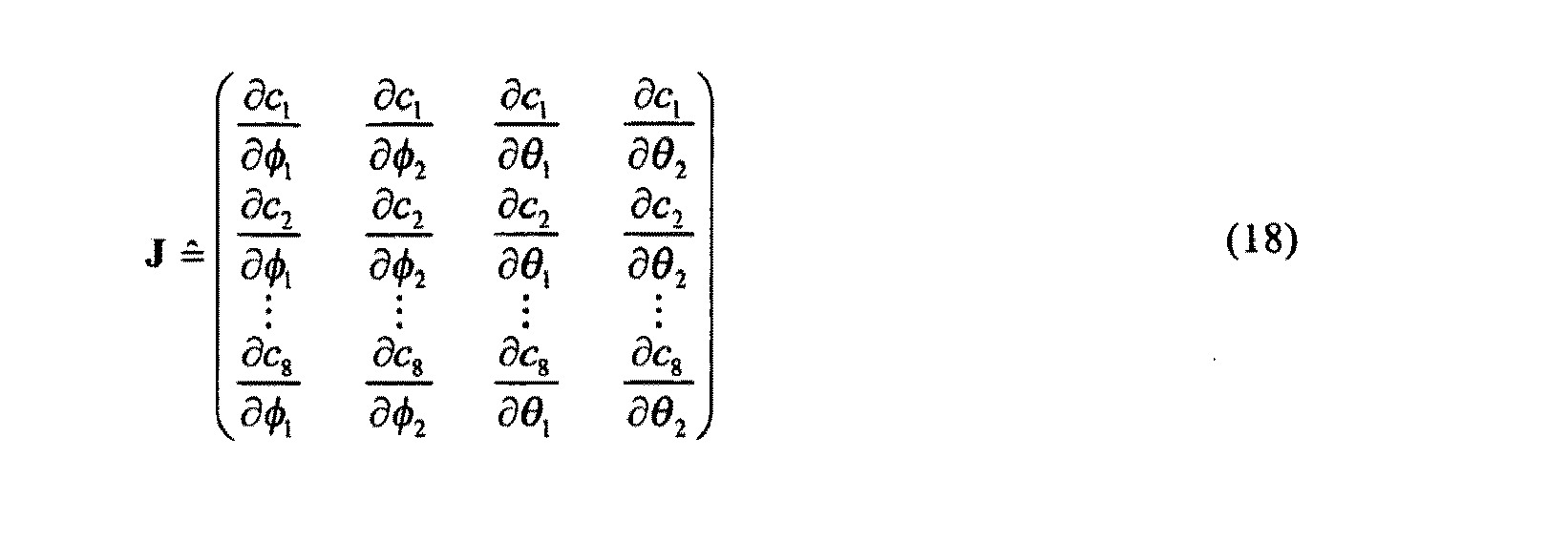
avec c1,..., c8 qui sont les coefficients de prise des quatre lignes de retard décroissante. - Procédé selon la revendication 7, dans lequel lesdits paramètres sont consolidés dans un vecteur θ qui est mise à jour conformément à la règle :

ou la règle simplifiée suivante sur la base seulement du signe
avec ∇HLP(θ) égal au gradient de Hlp(θ) par rapport à θ□. - Procédé selon la revendication 1, dans lequel lesdits dispositifs optiques comprennent un contrôleur de polarisation (12) avec des angles de contrôle φ1, φ2 et deux rotateurs optiques (14) avec des angles de rotation θ1 et θ2 et lesdits paramètres comprennent lesdits angles de contrôle φ1, φ2 et lesdits angles de rotation θ1, θ2.
- Procédé selon la revendication, dans lequel entre le contrôleur (12) et un rotateur optique (14) et entre les rotateurs optiques (14) se trouvent des fibres (13) qui induisent un retard d'unité différentiel prédéterminé maintenant la polarisation.
- Compensateur PMD (10) dans un système de communication à fibre optique adapté afin d'appliquer le procédé selon une quelconque des revendications ci-dessus et comprenant une cascade de dispositifs optiques ajustables (12, 14) via lesquels passe un signal optique à compenser et un système d'ajustement (15, 16) qui prend les composants y1(t) et y2(t) sur les deux polarisations orthogonales provenant du signal de sortie de compensateur avec le système d'ajustement comprenant un contrôleur (15, 16) qui sur la base desdits composants prélevés calcule les paramètres de Stokes S0, S1, S2, S3 dans un nombre Q de fréquences différentes du signal de sortie de compensateur et émet des signaux de commande pour au moins certains desdits dispositifs optiques ajustables (12, 14) de manière à rendre virtuellement constants les paramètres de Stokes calculés informatiquement aux différentes fréquences.
- Compensateur (10) selon la revendication 14, caractérisé en ce que lesdits dispositifs optiques (12, 14) comprennent un contrôleur de polarisation (12) avec des angles de contrôle φ1, φ2 et deux rotateurs optiques (14) avec des angles de rotation θ1 et θ2 et dans lequel lesdits paramètres qui sont ajustés consistent en lesdits angles de commande φ1, φ2 et lesdits angles de rotation θ1, θ2.
- Compensateur selon la revendication 15, caractérisé en ce que entre le contrôleur (12) et un rotateur optique (14) et entre les rotateurs optiques (14) se trouvent des fibres (13) qui induisent un retard d'unité différentielle prédéterminé maintenant la polarisation.
Applications Claiming Priority (3)
| Application Number | Priority Date | Filing Date | Title |
|---|---|---|---|
| IT2001MI002632A ITMI20012632A1 (it) | 2001-12-13 | 2001-12-13 | Metodo basato su parametri di stokes per la regolazione adattativa dicompensatori di pmd in sistemi di comunicazione a fibra ottica e compe |
| ITMI20012632 | 2001-12-13 | ||
| PCT/IB2002/005446 WO2003050984A1 (fr) | 2001-12-13 | 2002-11-29 | Compensateur de dispersion de mode de polarisation |
Publications (2)
| Publication Number | Publication Date |
|---|---|
| EP1456979A1 EP1456979A1 (fr) | 2004-09-15 |
| EP1456979B1 true EP1456979B1 (fr) | 2013-08-28 |
Family
ID=11448692
Family Applications (1)
| Application Number | Title | Priority Date | Filing Date |
|---|---|---|---|
| EP02783475.3A Expired - Lifetime EP1456979B1 (fr) | 2001-12-13 | 2002-11-29 | Compensateur de dispersion de mode de polarisation |
Country Status (8)
| Country | Link |
|---|---|
| US (1) | US7359582B2 (fr) |
| EP (1) | EP1456979B1 (fr) |
| JP (1) | JP2005512455A (fr) |
| CN (2) | CN1802804A (fr) |
| AU (1) | AU2002347546A1 (fr) |
| CA (1) | CA2468932A1 (fr) |
| IT (1) | ITMI20012632A1 (fr) |
| WO (1) | WO2003050984A1 (fr) |
Families Citing this family (12)
| Publication number | Priority date | Publication date | Assignee | Title |
|---|---|---|---|---|
| ITMI20040446A1 (it) * | 2004-03-09 | 2004-06-09 | Marconi Comm Spa | Sistema metodo e apparato per la compensazione della pmd e contemporanea demultiplazione di coppie di segnali multiplati ion polarizzazione |
| WO2005093975A1 (fr) | 2004-03-25 | 2005-10-06 | Fujitsu Limited | Compensateur de dispersion de mode de polarisation et procede de compensation de dispersion du mode de polarisation |
| ES2259267B1 (es) * | 2005-03-05 | 2007-10-01 | Universidad Politecnica De Valencia | Metodo y dispositivo de medida del estado de polarizacion y de la dispersion modal por polarizacion en sistemas fotonicos de transmision. |
| CN100362379C (zh) * | 2005-11-10 | 2008-01-16 | 北京北方烽火科技有限公司 | 自适应宽带偏振模色散补偿方法和装置 |
| CN1836603B (zh) * | 2006-04-14 | 2010-08-11 | 郑国宏 | 鞋楦定位固紧装置及其专用鞋楦 |
| GB2470963A (en) | 2009-06-12 | 2010-12-15 | Polariq Ltd | A polarisation controller |
| US9515745B2 (en) * | 2014-03-06 | 2016-12-06 | Cisco Technology, Inc. | Adaptive equalization in coherent receivers using a Stokes space update algorithm |
| CN104944120B (zh) * | 2015-07-02 | 2017-04-12 | 宁波慈星股份有限公司 | 一种用于机器人制鞋流水线的工装座 |
| CN104905493A (zh) * | 2015-07-02 | 2015-09-16 | 宁波慈星股份有限公司 | 一种用于机器人制鞋流水线的鞋底固定装置 |
| CN106360883B (zh) * | 2016-11-10 | 2019-05-03 | 张新利 | 自动勒楦机 |
| CN108433252B (zh) * | 2018-05-17 | 2020-10-09 | 浙江三益鞋业有限公司 | 一种压鞋底机 |
| CN119472087B (zh) * | 2024-10-28 | 2026-05-05 | 中山大学 | 一种基于雅可比矩阵的偏振控制方法以及系统 |
Family Cites Families (7)
| Publication number | Priority date | Publication date | Assignee | Title |
|---|---|---|---|---|
| US3559428A (en) * | 1969-06-02 | 1971-02-02 | Usm Corp | Shoe bottom roughing machines |
| US3775797A (en) * | 1972-02-18 | 1973-12-04 | Kamborian Jacob S Jr | Method and machine for lasting |
| SU967463A1 (ru) * | 1981-03-11 | 1982-10-23 | Киевский Филиал Ленинградского Специального Конструкторского Бюро По Проектированию Кожгалантерейных,Обувных,Меховых Машин И Средств Автоматизации | Машина дл формовани носочной части юфтевой обуви |
| US5227623A (en) | 1992-01-31 | 1993-07-13 | Hewlett-Packard Company | Method and apparatus for measuring polarization mode dispersion in optical devices |
| US6567167B1 (en) * | 2000-02-16 | 2003-05-20 | Massachusetts Institute Of Technology | Compensating polarization mode dispersion in fiber optic transmission system |
| ATE369672T1 (de) * | 2000-07-06 | 2007-08-15 | Alcatel Lucent | Kompensation der polarisationsmodendispersion |
| ITTO20020169A1 (it) * | 2002-02-28 | 2003-08-28 | Telecom Italia Lab Spa | Apparato per compensare gli effetti di dispersione di polarizzazione e metodo corrispondente. |
-
2001
- 2001-12-13 IT IT2001MI002632A patent/ITMI20012632A1/it unknown
-
2002
- 2002-11-29 AU AU2002347546A patent/AU2002347546A1/en not_active Abandoned
- 2002-11-29 CA CA002468932A patent/CA2468932A1/fr not_active Abandoned
- 2002-11-29 US US10/498,613 patent/US7359582B2/en not_active Expired - Fee Related
- 2002-11-29 CN CN02828028.8A patent/CN1802804A/zh active Pending
- 2002-11-29 EP EP02783475.3A patent/EP1456979B1/fr not_active Expired - Lifetime
- 2002-11-29 WO PCT/IB2002/005446 patent/WO2003050984A1/fr not_active Ceased
- 2002-11-29 JP JP2003551930A patent/JP2005512455A/ja active Pending
- 2002-12-13 CN CNB021560757A patent/CN1298267C/zh not_active Expired - Fee Related
Also Published As
| Publication number | Publication date |
|---|---|
| US20050141802A1 (en) | 2005-06-30 |
| AU2002347546A1 (en) | 2003-06-23 |
| AU2002347546A8 (en) | 2003-06-23 |
| CN1423983A (zh) | 2003-06-18 |
| WO2003050984A8 (fr) | 2003-08-28 |
| CA2468932A1 (fr) | 2003-06-19 |
| JP2005512455A (ja) | 2005-04-28 |
| CN1802804A (zh) | 2006-07-12 |
| EP1456979A1 (fr) | 2004-09-15 |
| ITMI20012632A1 (it) | 2003-06-13 |
| US7359582B2 (en) | 2008-04-15 |
| WO2003050984A1 (fr) | 2003-06-19 |
| CN1298267C (zh) | 2007-02-07 |
Similar Documents
| Publication | Publication Date | Title |
|---|---|---|
| US5930414A (en) | Method and apparatus for automatic compensation of first-order polarization mode dispersion (PMD) | |
| US20050175339A1 (en) | Dynamic broadband optical equalizer | |
| US6538787B1 (en) | Apparatus and method for polarization mode dispersion emulation and compensation | |
| US5793511A (en) | Optical receiver with an equalizing circuit for PMD-induced interference, and system with such an optical receiver | |
| US6016379A (en) | Method and facility for equalizing an electric signal distorted due to interference in the optical domain | |
| US7359582B2 (en) | Method based on stokes parameters for the adaptive adjustment of PMD compensators in optical fiber communication systems and compensator in accordance with said method | |
| US20060034614A1 (en) | Adaptive optical equalization for chromatic and/or polarization mode dispersion compensation and joint opto-electronic equalizer architecture | |
| US7403717B2 (en) | Method and apparatus for first-order polarization mode dispersion compensation | |
| Noé et al. | PMD in high-bit-rate transmission and means for its mitigation | |
| US7444082B2 (en) | Polarisation mode dispersion compensator using a mean square error technique | |
| EP1410538B1 (fr) | Systeme de communication optique et appareil de compensation ou d'emulation des effets de la pmd | |
| US6980744B1 (en) | Methods and systems for polarization mode dispersion compensation | |
| US7024058B2 (en) | Apparatus for compensating polarization mode dispersion | |
| US6996299B2 (en) | All-frequency PMD compensator and emulator | |
| WO2005013519A1 (fr) | Egaliseur optique adaptatif dynamique large bande | |
| EP1479181B1 (fr) | Appareil et procede destines a attenuer les effets de la dispersion de mode de polarisation | |
| US20030185578A1 (en) | Receiving device for disturbed optical signals with generation of a feedback signal by correlation, and method of generating such a feedback signal | |
| JP6273713B2 (ja) | 偏波障害エミュレータ及び偏波障害エミュレート方法 | |
| JPH06235880A (ja) | 光ファイバ偏波分散等化光回路 | |
| Sultanov et al. | Simulation of polarization mode dispersion compensation based on EMTY-model and nonlinear optimization | |
| EP1376909A1 (fr) | Compensateur de distorsion de signaux optiques avec un temps de réponse accéléré |
Legal Events
| Date | Code | Title | Description |
|---|---|---|---|
| PUAI | Public reference made under article 153(3) epc to a published international application that has entered the european phase |
Free format text: ORIGINAL CODE: 0009012 |
|
| 17P | Request for examination filed |
Effective date: 20040705 |
|
| AK | Designated contracting states |
Kind code of ref document: A1 Designated state(s): AT BE BG CH CY CZ DE DK EE ES FI FR GB GR IE IT LI LU MC NL PT SE SK TR |
|
| AX | Request for extension of the european patent |
Extension state: AL LT LV MK RO SI |
|
| RAP1 | Party data changed (applicant data changed or rights of an application transferred) |
Owner name: ERICSSON AB |
|
| RAP1 | Party data changed (applicant data changed or rights of an application transferred) |
Owner name: ERICSSON AB |
|
| 17Q | First examination report despatched |
Effective date: 20100115 |
|
| RAP1 | Party data changed (applicant data changed or rights of an application transferred) |
Owner name: ERICSSON AB |
|
| REG | Reference to a national code |
Ref country code: DE Ref legal event code: R079 Ref document number: 60245444 Country of ref document: DE Free format text: PREVIOUS MAIN CLASS: H04B0010180000 Ipc: H04B0010256900 |
|
| RIC1 | Information provided on ipc code assigned before grant |
Ipc: G02B 6/27 20060101ALI20130312BHEP Ipc: H04B 10/2569 20130101AFI20130312BHEP |
|
| GRAP | Despatch of communication of intention to grant a patent |
Free format text: ORIGINAL CODE: EPIDOSNIGR1 |
|
| INTG | Intention to grant announced |
Effective date: 20130502 |
|
| GRAP | Despatch of communication of intention to grant a patent |
Free format text: ORIGINAL CODE: EPIDOSNIGR1 |
|
| INTG | Intention to grant announced |
Effective date: 20130613 |
|
| GRAS | Grant fee paid |
Free format text: ORIGINAL CODE: EPIDOSNIGR3 |
|
| GRAA | (expected) grant |
Free format text: ORIGINAL CODE: 0009210 |
|
| AK | Designated contracting states |
Kind code of ref document: B1 Designated state(s): AT BE BG CH CY CZ DE DK EE ES FI FR GB GR IE IT LI LU MC NL PT SE SK TR |
|
| REG | Reference to a national code |
Ref country code: GB Ref legal event code: FG4D |
|
| REG | Reference to a national code |
Ref country code: CH Ref legal event code: EP |
|
| REG | Reference to a national code |
Ref country code: AT Ref legal event code: REF Ref document number: 629826 Country of ref document: AT Kind code of ref document: T Effective date: 20130915 |
|
| REG | Reference to a national code |
Ref country code: IE Ref legal event code: FG4D |
|
| REG | Reference to a national code |
Ref country code: DE Ref legal event code: R096 Ref document number: 60245444 Country of ref document: DE Effective date: 20131024 |
|
| REG | Reference to a national code |
Ref country code: AT Ref legal event code: MK05 Ref document number: 629826 Country of ref document: AT Kind code of ref document: T Effective date: 20130828 |
|
| REG | Reference to a national code |
Ref country code: NL Ref legal event code: VDEP Effective date: 20130828 |
|
| PG25 | Lapsed in a contracting state [announced via postgrant information from national office to epo] |
Ref country code: PT Free format text: LAPSE BECAUSE OF FAILURE TO SUBMIT A TRANSLATION OF THE DESCRIPTION OR TO PAY THE FEE WITHIN THE PRESCRIBED TIME-LIMIT Effective date: 20131230 Ref country code: SE Free format text: LAPSE BECAUSE OF FAILURE TO SUBMIT A TRANSLATION OF THE DESCRIPTION OR TO PAY THE FEE WITHIN THE PRESCRIBED TIME-LIMIT Effective date: 20130828 Ref country code: AT Free format text: LAPSE BECAUSE OF FAILURE TO SUBMIT A TRANSLATION OF THE DESCRIPTION OR TO PAY THE FEE WITHIN THE PRESCRIBED TIME-LIMIT Effective date: 20130828 Ref country code: CY Free format text: LAPSE BECAUSE OF FAILURE TO SUBMIT A TRANSLATION OF THE DESCRIPTION OR TO PAY THE FEE WITHIN THE PRESCRIBED TIME-LIMIT Effective date: 20130703 |
|
| REG | Reference to a national code |
Ref country code: NL Ref legal event code: VDEP Effective date: 20130828 |
|
| PG25 | Lapsed in a contracting state [announced via postgrant information from national office to epo] |
Ref country code: BE Free format text: LAPSE BECAUSE OF FAILURE TO SUBMIT A TRANSLATION OF THE DESCRIPTION OR TO PAY THE FEE WITHIN THE PRESCRIBED TIME-LIMIT Effective date: 20130828 Ref country code: FI Free format text: LAPSE BECAUSE OF FAILURE TO SUBMIT A TRANSLATION OF THE DESCRIPTION OR TO PAY THE FEE WITHIN THE PRESCRIBED TIME-LIMIT Effective date: 20130828 Ref country code: ES Free format text: LAPSE BECAUSE OF FAILURE TO SUBMIT A TRANSLATION OF THE DESCRIPTION OR TO PAY THE FEE WITHIN THE PRESCRIBED TIME-LIMIT Effective date: 20130828 Ref country code: GR Free format text: LAPSE BECAUSE OF FAILURE TO SUBMIT A TRANSLATION OF THE DESCRIPTION OR TO PAY THE FEE WITHIN THE PRESCRIBED TIME-LIMIT Effective date: 20131129 |
|
| PG25 | Lapsed in a contracting state [announced via postgrant information from national office to epo] |
Ref country code: CY Free format text: LAPSE BECAUSE OF FAILURE TO SUBMIT A TRANSLATION OF THE DESCRIPTION OR TO PAY THE FEE WITHIN THE PRESCRIBED TIME-LIMIT Effective date: 20130828 |
|
| PG25 | Lapsed in a contracting state [announced via postgrant information from national office to epo] |
Ref country code: EE Free format text: LAPSE BECAUSE OF FAILURE TO SUBMIT A TRANSLATION OF THE DESCRIPTION OR TO PAY THE FEE WITHIN THE PRESCRIBED TIME-LIMIT Effective date: 20130828 Ref country code: NL Free format text: LAPSE BECAUSE OF FAILURE TO SUBMIT A TRANSLATION OF THE DESCRIPTION OR TO PAY THE FEE WITHIN THE PRESCRIBED TIME-LIMIT Effective date: 20130828 Ref country code: CZ Free format text: LAPSE BECAUSE OF FAILURE TO SUBMIT A TRANSLATION OF THE DESCRIPTION OR TO PAY THE FEE WITHIN THE PRESCRIBED TIME-LIMIT Effective date: 20130828 Ref country code: DK Free format text: LAPSE BECAUSE OF FAILURE TO SUBMIT A TRANSLATION OF THE DESCRIPTION OR TO PAY THE FEE WITHIN THE PRESCRIBED TIME-LIMIT Effective date: 20130828 Ref country code: SK Free format text: LAPSE BECAUSE OF FAILURE TO SUBMIT A TRANSLATION OF THE DESCRIPTION OR TO PAY THE FEE WITHIN THE PRESCRIBED TIME-LIMIT Effective date: 20130828 |
|
| PG25 | Lapsed in a contracting state [announced via postgrant information from national office to epo] |
Ref country code: IT Free format text: LAPSE BECAUSE OF FAILURE TO SUBMIT A TRANSLATION OF THE DESCRIPTION OR TO PAY THE FEE WITHIN THE PRESCRIBED TIME-LIMIT Effective date: 20130828 |
|
| REG | Reference to a national code |
Ref country code: DE Ref legal event code: R097 Ref document number: 60245444 Country of ref document: DE |
|
| REG | Reference to a national code |
Ref country code: CH Ref legal event code: PL |
|
| PLBE | No opposition filed within time limit |
Free format text: ORIGINAL CODE: 0009261 |
|
| STAA | Information on the status of an ep patent application or granted ep patent |
Free format text: STATUS: NO OPPOSITION FILED WITHIN TIME LIMIT |
|
| GBPC | Gb: european patent ceased through non-payment of renewal fee |
Effective date: 20131129 |
|
| PG25 | Lapsed in a contracting state [announced via postgrant information from national office to epo] |
Ref country code: LI Free format text: LAPSE BECAUSE OF NON-PAYMENT OF DUE FEES Effective date: 20131130 Ref country code: CH Free format text: LAPSE BECAUSE OF NON-PAYMENT OF DUE FEES Effective date: 20131130 Ref country code: MC Free format text: LAPSE BECAUSE OF FAILURE TO SUBMIT A TRANSLATION OF THE DESCRIPTION OR TO PAY THE FEE WITHIN THE PRESCRIBED TIME-LIMIT Effective date: 20130828 |
|
| 26N | No opposition filed |
Effective date: 20140530 |
|
| REG | Reference to a national code |
Ref country code: DE Ref legal event code: R082 Ref document number: 60245444 Country of ref document: DE Representative=s name: BURCHARDI, THOMAS, DIPL.-ING. UNIV., DE |
|
| REG | Reference to a national code |
Ref country code: FR Ref legal event code: ST Effective date: 20140731 |
|
| REG | Reference to a national code |
Ref country code: IE Ref legal event code: MM4A |
|
| REG | Reference to a national code |
Ref country code: DE Ref legal event code: R097 Ref document number: 60245444 Country of ref document: DE Effective date: 20140530 |
|
| PG25 | Lapsed in a contracting state [announced via postgrant information from national office to epo] |
Ref country code: IE Free format text: LAPSE BECAUSE OF NON-PAYMENT OF DUE FEES Effective date: 20131129 |
|
| PG25 | Lapsed in a contracting state [announced via postgrant information from national office to epo] |
Ref country code: GB Free format text: LAPSE BECAUSE OF NON-PAYMENT OF DUE FEES Effective date: 20131129 Ref country code: FR Free format text: LAPSE BECAUSE OF NON-PAYMENT OF DUE FEES Effective date: 20131202 |
|
| PGFP | Annual fee paid to national office [announced via postgrant information from national office to epo] |
Ref country code: DE Payment date: 20141128 Year of fee payment: 13 |
|
| PG25 | Lapsed in a contracting state [announced via postgrant information from national office to epo] |
Ref country code: TR Free format text: LAPSE BECAUSE OF FAILURE TO SUBMIT A TRANSLATION OF THE DESCRIPTION OR TO PAY THE FEE WITHIN THE PRESCRIBED TIME-LIMIT Effective date: 20130828 |
|
| PG25 | Lapsed in a contracting state [announced via postgrant information from national office to epo] |
Ref country code: BG Free format text: LAPSE BECAUSE OF FAILURE TO SUBMIT A TRANSLATION OF THE DESCRIPTION OR TO PAY THE FEE WITHIN THE PRESCRIBED TIME-LIMIT Effective date: 20130828 Ref country code: LU Free format text: LAPSE BECAUSE OF NON-PAYMENT OF DUE FEES Effective date: 20131129 |
|
| REG | Reference to a national code |
Ref country code: DE Ref legal event code: R119 Ref document number: 60245444 Country of ref document: DE |
|
| PG25 | Lapsed in a contracting state [announced via postgrant information from national office to epo] |
Ref country code: DE Free format text: LAPSE BECAUSE OF NON-PAYMENT OF DUE FEES Effective date: 20160601 |