EP1457155A1 - Appareil de tomographie par ordinateur (ct) a rayons x - Google Patents
Appareil de tomographie par ordinateur (ct) a rayons x Download PDFInfo
- Publication number
- EP1457155A1 EP1457155A1 EP02783797A EP02783797A EP1457155A1 EP 1457155 A1 EP1457155 A1 EP 1457155A1 EP 02783797 A EP02783797 A EP 02783797A EP 02783797 A EP02783797 A EP 02783797A EP 1457155 A1 EP1457155 A1 EP 1457155A1
- Authority
- EP
- European Patent Office
- Prior art keywords
- ray
- fov size
- changing
- tomogram
- fov
- Prior art date
- Legal status (The legal status is an assumption and is not a legal conclusion. Google has not performed a legal analysis and makes no representation as to the accuracy of the status listed.)
- Withdrawn
Links
Images



Classifications
-
- A—HUMAN NECESSITIES
- A61—MEDICAL OR VETERINARY SCIENCE; HYGIENE
- A61B—DIAGNOSIS; SURGERY; IDENTIFICATION
- A61B6/00—Apparatus or devices for radiation diagnosis; Apparatus or devices for radiation diagnosis combined with radiation therapy equipment
- A61B6/44—Constructional features of apparatus for radiation diagnosis
- A61B6/4429—Constructional features of apparatus for radiation diagnosis related to the mounting of source units and detector units
- A61B6/4435—Constructional features of apparatus for radiation diagnosis related to the mounting of source units and detector units the source unit and the detector unit being coupled by a rigid structure
- A61B6/4441—Constructional features of apparatus for radiation diagnosis related to the mounting of source units and detector units the source unit and the detector unit being coupled by a rigid structure the rigid structure being a C-arm or U-arm
-
- A—HUMAN NECESSITIES
- A61—MEDICAL OR VETERINARY SCIENCE; HYGIENE
- A61B—DIAGNOSIS; SURGERY; IDENTIFICATION
- A61B6/00—Apparatus or devices for radiation diagnosis; Apparatus or devices for radiation diagnosis combined with radiation therapy equipment
- A61B6/04—Positioning of patients; Tiltable beds or the like
- A61B6/0478—Chairs
-
- A—HUMAN NECESSITIES
- A61—MEDICAL OR VETERINARY SCIENCE; HYGIENE
- A61B—DIAGNOSIS; SURGERY; IDENTIFICATION
- A61B6/00—Apparatus or devices for radiation diagnosis; Apparatus or devices for radiation diagnosis combined with radiation therapy equipment
- A61B6/46—Arrangements for interfacing with the operator or the patient
- A61B6/467—Arrangements for interfacing with the operator or the patient characterised by special input means
- A61B6/469—Arrangements for interfacing with the operator or the patient characterised by special input means for selecting a region of interest [ROI]
-
- A—HUMAN NECESSITIES
- A61—MEDICAL OR VETERINARY SCIENCE; HYGIENE
- A61B—DIAGNOSIS; SURGERY; IDENTIFICATION
- A61B6/00—Apparatus or devices for radiation diagnosis; Apparatus or devices for radiation diagnosis combined with radiation therapy equipment
- A61B6/50—Apparatus or devices for radiation diagnosis; Apparatus or devices for radiation diagnosis combined with radiation therapy equipment specially adapted for specific body parts; specially adapted for specific clinical applications
- A61B6/51—Apparatus or devices for radiation diagnosis; Apparatus or devices for radiation diagnosis combined with radiation therapy equipment specially adapted for specific body parts; specially adapted for specific clinical applications for dentistry
-
- A—HUMAN NECESSITIES
- A61—MEDICAL OR VETERINARY SCIENCE; HYGIENE
- A61B—DIAGNOSIS; SURGERY; IDENTIFICATION
- A61B6/00—Apparatus or devices for radiation diagnosis; Apparatus or devices for radiation diagnosis combined with radiation therapy equipment
- A61B6/06—Diaphragms
Definitions
- the present invention relates to an X-ray CT apparatus which radiates X-rays to a portion of an object to be examined and processes a projection image thereof to create a tomogram, more particularly to an X-ray CT apparatus which can create a tomogram on a portion of the object as in dental care.
- Such a problem can be solved by three-dimensionally observing the form of teethridge and nearby bones using a conventional X-ray CT apparatus.
- the conventional X-ray CT apparatus does not image only one portion of a section of a body such as teethridge and nearby bones, but radiates X-rays to the whole area and obtains a tomogram of a desired portion from the obtained whole-area image.
- the desired portion being the subject here is the form of teethridge and the nearby bones, the image thereof becomes small compared with the entire image. Therefore, when the desired portion is small, the extracted image is small and difficult to be recognized since the image thereof is extracted from the entire image.
- a tomogram of the desired portion can be easily imaged by constructing an X-ray CT apparatus so as to radiate X-rays only to the desired portion and create a projection image thereof.
- an X-ray CT apparatus so as to radiate X-rays only to the desired portion and create a projection image thereof.
- One example of the apparatus which radiates X-rays only to the desired portion to create a CT image thereof is described in Japanese Unexamined Patent Publication 2000-139902.
- Japanese Unexamined Patent Publication 2000-139902 because X-rays are locally radiated to a local portion by using an X-ray cone beam collimator, prevention of excessive radiation exposure of the object is taken into consideration.
- the collimator of an X-ray generator has to be set in every imaging and the selecting operation is complicated. Therefore, it is difficult to image an arbitrary portion of an arbitrary size of the object. This problem is not taken into consideration at all in Japanese Unexamined Patent Publication 2000-139902.
- An object of the present invention is to provide an X-ray CT apparatus which can image an arbitrary portion of an arbitrary size of the object.
- an X-ray CT apparatus includes: an X-ray generating means for generating X-rays; an X-ray detecting means arranged opposite to the X-ray generating means for two-dimensionally detecting a dose of X-rays passing through an object to be examined; means for holding the X-ray generating means and the X-ray detecting means so that the object is placed therebetween; rotation driving means for driving the holding means to rotate around the object; image processing means for producing a tomogram of the object on the basis of the X-ray dose detected by the X-ray detecting means; and display means for displaying the tomogram, further including means for changing a size of field of view (FOV) in accordance with a detecting portion of the object displayed on the display means.
- FOV field of view
- a tomogram of one tooth is created by image processing means from the X-ray dose based on a one-tooth FOV size, and displayed by the display means.
- FOV size is set for a whole jaw
- a tomogram of whole jaw is created by the image processing means from the X-ray dose based on a whole-jaw FOV size, and displayed by the display means.
- the FOV size changing means includes X-ray converting means for converting the X-rays into visible light; light receiving means for converting the visible light converted by the X-ray converting means into electrical signals; and means for changing a portion of the visible light of the X-ray converting means necessary for creating the tomogram.
- the X-ray detecting means which includes X-ray converting means such as an image intensifier (I.I.) device, light receiving means such as a CCD camera, and an optical system which forms an image of the image intensifier device on the CCD camera.
- the optical system includes an electric collimator for adjusting a light amount. When various areas are imaged, the optical system adjusts a size of image and brightness of the electric collimator, thus an optimum CT image can be obtained.
- the X-ray detecting means is a two-dimensional X-ray flat sensor
- the FOV size changing means includes means for changing the region necessary for creating the tomogram using electrical signals converted by the two-dimensional X-ray flat sensor.
- the FOV size changing means includes means for inputting a desired FOV size by moving a cursor of a pointing device to an FOV size changing switch displayed on the display means and control means for changing the FOV size to the size input by the input means.
- the input of FOV change can be certainly and promptly set by operating the FOV changing switch displayed on a monitor of the display means.
- an image of the input X-ray dose can be obtained under more preferable X-ray conditions of the X-ray detecting means changed due to change of FOV size, with adjustment of tube voltage, tube current, and radiation time of the X-ray generator.
- the apparatus includes means for adjusting a size of the tomogram displayed by the display means.
- a portion of an arbitrary size can be imaged.
- the adjusting means includes means for adjusting a distance between the X-ray generating means and the X-ray detecting means on the holding means.
- the adjusting means is designed to adjust the distance between the X-ray generating means and the X-ray detecting means by extending and retracting a part of the holding means.
- the distance therebetween can be adjusted by extending and retracting a part of the distance adjusting means.
- the holding means has a U-shaped arm and is provided with the X-ray generating means and the X-ray detecting means on each end of the arm, and the rotation driving means is designed to rotate the U-shaped arm around its intermediate portion.
- the rotation driving means rotates X-rays around the object by rotating the U-shaped arm around its intermediate portion, thus a fluoroscopic image necessary for creating a tomogram can be obtained.
- the apparatus includes means for extending a tomogram of the FOV size changed by the FOV size changing means.
- FOV size changing means By switching the FOV size, both the whole face and a single tooth can be enlarged in the image, whereby it becomes easy to make treatment plan of implant surgery and to observe passage after surgery.
- the apparatus includes means for determining a position of the object so that an arbitrary region of the object is located at the rotation center of the X-ray generating means and the X-ray detecting means.
- the position can be freely determined in a three-dimensional space by electrically moving the object up and down, back and forth, and from side to side, or rotating him/her.
- the imaging position thereof can be determined by moving the head back and forth and from side to side or rotating it in accordance with the shape thereof.
- Fig.1 is a front view of appearance of a scanner mechanism unit of an X-ray CT apparatus according to one embodiment of the invention.
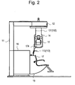
- Fig.2 is a left side view of Fig.1.
- Fig.3 is a top view of Fig.1.
- Fig.4 is a block diagram showing schematic structure of an X-ray CT apparatus according to one embodiment of the invention.
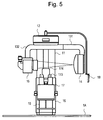
- Fig.5 is a diagram showing change of appearance of an X-ray CT apparatus when a different region is imaged.
- the X-ray CT apparatus includes the scanner mechanism unit 1 and the image processing unit 2.
- Fig.1 is a front view of appearance of the scanner mechanism unit 1 of the X-ray CT apparatus according to one embodiment of the invention.
- Fig.2 is a left side view of Fig.1, and
- Fig.3 is a top view of Fig.1.
- Fig.4 is a block diagram showing schematic structure of the X-ray CT apparatus according to one embodiment of the invention.
- Fig.5 is a diagram showing appearance of the X-ray CT apparatus when a relatively large portion is imaged.
- the scanner mechanism unit 1 includes the column 11, the U-shaped arm rotation driving unit 12, the U-shaped arms 131 and 132, the X-ray generator 14, the X-ray information inputting means 15, the control means 16, the chair 17, the console 18, the chair driving device 19, and the mat switch 1A.
- the column 11 has a reverse L shape and has the U-shaped arm driving unit 12 on the edge.
- the U-shaped arm driving unit 12 holds the suspended U-shaped arms 131 and 132 and rotates the U-shaped arms 131 and 132 at a predetermined speed with respect to the edge of the reverse L-shaped column 11 being a rotation center.
- the X-ray generator 14 is designed to generate X-rays and provided on the edge of the U-shaped arm 131.
- the X-ray information inputting means 15 is arranged opposite to the X-ray generator 14 and mounted on the edge of the U-shaped arm 132, which is designed to two-dimensionally detect X-ray dose passing through the object. That is, the X-ray generator 14 is arranged opposite to the X-ray information inputting means 15 in relation to the U-shaped arms 131 and 132.
- the U-shaped arms 131 and 132 are driven to rotate by approximately 405 degrees around the edge of the reverse L-shaped column 11 being the rotation center by the U-shaped arm rotation driving unit 12. Although the imaging range is 360 degrees, the rotation range is set to be wider by 45 degrees so as to begin imaging from the point where a rotation speed comes to be constant.
- the U-shaped arm 131 can be freely extended and retracted in a radius direction by sliding the inside thereof, and thus the distance between the X-ray generator 14 and the X-ray information inputting means 15 is adjusted.
- Fig.5 illustrates the state that the U-shaped arm 131 is extended to the maximum
- Fig.1 illustrates the state that it is retracted to the maximum.
- the X-ray generator 14 radiates X-rays in pulses in synchronism with image collection to reduce X-ray exposure. The timing thereof is controlled by a position detection encoder built in the U-shaped arm rotation driving unit 12.
- the X-ray information inputting means 15 includes the CCD camera 151, the electric collimator 152, and the image intensifier (I.I.) device 153.
- the I.I. device 153 converts incident X-rays passing through the object into visible light.
- the CCD camera 151 receives the visible light converted by the I.I. device 153 and converts it into electrical signals.
- the X-ray information inputting means 15 can switch the imaging range in accordance with the imaging portion.
- the optical system is constructed so that the FOV size is set to be small when teeth are imaged, and it is set to be large when jaw and face are imaged.
- the X-ray information inputting means 15 changes a pixel size of the CCD camera 151 by switching the FOV size of the I.I. device 153 using the optical system including the electric collimator 152, whereby an FOV of a small size can be observed in detail.
- the control device 16 for controlling the entire scanner mechanism unit 1 is provided below the column 11. The control unit 16 controls X-ray conditions, the scanner mechanism unit 1, and X-ray radiation according to control signals from the image processing unit 2. Meanwhile, instead of the I.I.
- an imaging plate a two-dimensional flat X-ray sensor, and the like also may be used.
- the two-dimensional flat X-ray detector is used, X-rays can be directly converted into electrical signals without through a CCD camera or the like, whereby it contributes to making the X-ray CT apparatus smaller and lighter.
- each element arranged in a direction of X-ray input is in a state of being activated or inactivated, and X-ray data is not obtained from the inactivated elements but from the activated elements.
- the chair 17 is provided so that the head of the object is located on a rotation center axis of the U-shaped arms 131 and 132.
- the chair 17 is attached to the side of the column 4, including the chair driving device 19 for adjusting an imaging position in response to difference of object's seated heights and finely adjusting an imaging position in response to an imaging portion, which can be electrically moved freely in a three-dimensional space, i.e., up and down, back and forth, and from side to side.
- the chair driving device 19 also can be moved in a three-dimensional space in X-, Y-, and Z-directions and driven to rotate around the head being the rotation center.
- the chair includes the chair position detecting unit 171 for detecting the height of its seat and the shoulder position detecting unit 172 for detecting the position of shoulders so that the object's shoulders do not touch the rotating X-ray information inputting means 15. Meanwhile, the chair position detecting unit 171 is not shown in Fig.1 to Fig.3.
- the chair 17 is provided with the shoulder pad 173 and the head pad 174.
- the shoulder pad 173 includes the built-in shoulder position detecting unit 172. Further, the shoulder pad 173 is designed to rotate above by 90 degrees so as not to hinder the object sitting on the chair 17.
- Position signals detected by the chair position detecting unit 171 and the shoulder position detecting unit 172 are transmitted to the control device 16 and signal-processed here.
- the head pad 174 has a band or the like for fixing the object's head in imaging. Further, an attaching position of the head pad 173 can be moved back and forth and from side to side to move the imaging portion in accordance with the shape of head.
- the mat switch 1A is a mat provided so as to surround a rotating area 133 of the U-shaped arms 131 and 132. When a person or something goes into the mat switch 1A, it shuts the interlock so that the U-shaped arms 131 and 132 cannot rotate.
- the image processing unit 2 includes the image processing device 21, the CRT 22, the keyboard 23, the mouse 24, and a pointing device such as a trackball and a touch panel.
- the image processing device 21 takes in 288 X-ray fluoroscopic images with a 360-degree FOV, reconstructs those images into a two-dimensional image, and displays it on the monitor (CRT) 22.
- Image reconstruction done by the image processing device 21 is a known technique of cone-beam CT, in which multiple vertical information can be read in during one rotation of the U-shaped arm around a patient.
- 3D display software built in the image processing device 21 a 3D image can be created and displayed on the basis of the information. Because the shape can be three-dimensionally understood, the image is useful in making a plan of implant surgery.
- a method of switching the FOV size of this X-ray CT apparatus will be described.
- a cursor is moved onto an FOV size changing switch displayed on the monitor 22 by using the mouse 24.
- a selected FOV size is instructed from the image processing device 21 to the control unit 16.
- the control unit 16 outputs change of X-ray conditions (tube voltage and tube current) on the basis of the instructed FOV size.
- the control unit 16 outputs a signal to the electric collimator 152 for adjusting an FOV size switching signal of the I.I. device 153 and a light amount of the CCD camera.
- the I.I. device 153 if an FOV size is reduced and the X-ray conditions are the same as in a large FOV size, a light amount output to the CCD camera decreases.
- an image displayed on the CRT becomes dark and its contrast is deteriorated. Therefore, it is necessary to improve the X-ray conditions and activate a collimator of the front of the CCD camera in an opening direction to display an image having the same contrast as that of a large FOV size.
- an FOV size of X-rays input into the I.I. device 153 is set for the whole jaw, a tomogram of the whole jaw of the object is created by the image processing device 21 from an X-ray dose based on a radiation area of the whole jaw, and a tomogram of one tooth is displayed on the CRT 22.
- an FOV size of X-rays input into the I.I. device 153 is set for one tooth, a tomogram of one tooth of the object is created, and the tomogram of one tooth is displayed on the CRT 22.
- the X-ray generator 14 can be moved from the position shown in Fig.5 to the I.I. device 153 by electrically or manually changing the arm length of the U-shaped arms 131 and 132 to which the X-ray generator is attached as shown in Fig.1 and thus an arbitrary FOV size can be chosen. Accordingly, a portion needed for the examination by a doctor can be enlarged.
- a telescopic system utilizing a mechanism which changes a length of a supporter, described in Japanese Unexamined Patent Publication Hei. 8-112272, is employed. If the system is electrically driven, the motor or the like is used. If the system is manually driven, an operator properly adjusts an extendable arm. The details of the mechanism are omitted here.
- an image can be displayed and so three-dimensional observation can be done for evaluation of lower jaw before surgery and following after surgery. Therefore, medical accident in implant surgery can be prevented and diagnostic efficiency can be improved. Further, a panoramic image and a cephalometric image obtained in conventional X-ray imaging also can be displayed and simultaneously used with a three-dimensional image, whereby more accurate diagnosis can be conducted.
- an object's arbitrary portion of an arbitrary size can be imaged.
Landscapes
- Health & Medical Sciences (AREA)
- Life Sciences & Earth Sciences (AREA)
- Engineering & Computer Science (AREA)
- Medical Informatics (AREA)
- Radiology & Medical Imaging (AREA)
- Molecular Biology (AREA)
- Biophysics (AREA)
- Nuclear Medicine, Radiotherapy & Molecular Imaging (AREA)
- Optics & Photonics (AREA)
- Pathology (AREA)
- Physics & Mathematics (AREA)
- Biomedical Technology (AREA)
- Heart & Thoracic Surgery (AREA)
- High Energy & Nuclear Physics (AREA)
- Surgery (AREA)
- Animal Behavior & Ethology (AREA)
- General Health & Medical Sciences (AREA)
- Public Health (AREA)
- Veterinary Medicine (AREA)
- Human Computer Interaction (AREA)
- Dentistry (AREA)
- Oral & Maxillofacial Surgery (AREA)
- Apparatus For Radiation Diagnosis (AREA)
Applications Claiming Priority (3)
| Application Number | Priority Date | Filing Date | Title |
|---|---|---|---|
| JP2001375131 | 2001-12-10 | ||
| JP2001375131A JP2003175027A (ja) | 2001-12-10 | 2001-12-10 | X線ct装置 |
| PCT/JP2002/012857 WO2003049616A1 (fr) | 2001-12-10 | 2002-12-09 | Appareil de tomographie par ordinateur (ct) a rayons x |
Publications (2)
| Publication Number | Publication Date |
|---|---|
| EP1457155A1 true EP1457155A1 (fr) | 2004-09-15 |
| EP1457155A4 EP1457155A4 (fr) | 2005-07-27 |
Family
ID=19183554
Family Applications (1)
| Application Number | Title | Priority Date | Filing Date |
|---|---|---|---|
| EP02783797A Withdrawn EP1457155A4 (fr) | 2001-12-10 | 2002-12-09 | Appareil de tomographie par ordinateur (ct) a rayons x |
Country Status (5)
| Country | Link |
|---|---|
| US (1) | US7269242B2 (fr) |
| EP (1) | EP1457155A4 (fr) |
| JP (1) | JP2003175027A (fr) |
| CN (1) | CN100348157C (fr) |
| WO (1) | WO2003049616A1 (fr) |
Cited By (8)
| Publication number | Priority date | Publication date | Assignee | Title |
|---|---|---|---|---|
| WO2006108920A1 (fr) * | 2005-04-11 | 2006-10-19 | Planmeca Oy | Appareil de tomographie informatique |
| EP1721574A1 (fr) | 2005-08-08 | 2006-11-15 | Vatech Co., Ltd. | Appareil combinant radiographie panoramique, cephalometrique et tomographie assistée par ordinateur |
| EP1752099A2 (fr) | 2005-08-08 | 2007-02-14 | Vatech Co., Ltd. | Dispositif de photographie panoramique et tomodensitométrique combinée |
| WO2008028988A1 (fr) * | 2006-09-05 | 2008-03-13 | Palodex Group Oy | Appareil d'imagerie radiologique MéDICALe |
| EP1868504A4 (fr) * | 2005-03-14 | 2009-11-04 | Planmeca Oy | Imagerie tomographique dentaire assistee par ordinateur |
| WO2009156591A1 (fr) * | 2008-06-27 | 2009-12-30 | Planmeca Oy | Appareil de soins dentaires |
| EP2063783A4 (fr) * | 2006-09-22 | 2010-07-21 | Ray Co Ltd | Système d'imagerie dentaire complexe |
| EP2286728A1 (fr) * | 2009-08-19 | 2011-02-23 | J. Morita Manufacturing Corporation | Appareil médical à rayons X |
Families Citing this family (26)
| Publication number | Priority date | Publication date | Assignee | Title |
|---|---|---|---|---|
| JP4756849B2 (ja) * | 2004-11-05 | 2011-08-24 | 朝日レントゲン工業株式会社 | 頭頸部用コーンビームx線ct撮影装置 |
| JP4549870B2 (ja) * | 2005-01-07 | 2010-09-22 | 株式会社日立メディコ | X線ct装置 |
| US7991242B2 (en) | 2005-05-11 | 2011-08-02 | Optosecurity Inc. | Apparatus, method and system for screening receptacles and persons, having image distortion correction functionality |
| US20090174554A1 (en) | 2005-05-11 | 2009-07-09 | Eric Bergeron | Method and system for screening luggage items, cargo containers or persons |
| US7899232B2 (en) | 2006-05-11 | 2011-03-01 | Optosecurity Inc. | Method and apparatus for providing threat image projection (TIP) in a luggage screening system, and luggage screening system implementing same |
| US8494210B2 (en) | 2007-03-30 | 2013-07-23 | Optosecurity Inc. | User interface for use in security screening providing image enhancement capabilities and apparatus for implementing same |
| US7486759B2 (en) * | 2006-10-12 | 2009-02-03 | J. Morita Manufacturing Corporation | X-ray computer tomography apparatus |
| US8290119B2 (en) * | 2007-01-24 | 2012-10-16 | Imaging Sciences International Llc | Adjustable scanner |
| JP5539729B2 (ja) * | 2007-11-16 | 2014-07-02 | 株式会社モリタ製作所 | X線ct撮影装置 |
| JP2009136363A (ja) * | 2007-12-04 | 2009-06-25 | Yoshida Dental Mfg Co Ltd | X線撮影時の肩当たり確認方法および肩当たり確認装置 |
| WO2009105695A1 (fr) * | 2008-02-20 | 2009-08-27 | Imaging Sciences International Llc | Dispositif de balayage réglable |
| KR101259700B1 (ko) * | 2011-02-25 | 2013-05-06 | 이화여자대학교 산학협력단 | 엑스선 ct촬영 장치 |
| ES2675308T3 (es) | 2011-09-07 | 2018-07-10 | Rapiscan Systems, Inc. | Sistema de inspección de rayos X que integra datos de manifiesto con procesamiento de obtención de imágenes/detección |
| JP6096418B2 (ja) * | 2012-04-12 | 2017-03-15 | 株式会社堀場製作所 | X線検出装置 |
| CN102783967B (zh) * | 2012-08-23 | 2014-06-04 | 汕头市超声仪器研究所有限公司 | 一种乳腺ct设备 |
| KR20140044174A (ko) * | 2012-10-04 | 2014-04-14 | 주식회사바텍 | 엑스선 촬영장치 및 촬영방법 |
| CN103462631B (zh) * | 2013-09-22 | 2015-10-21 | 江苏美伦影像系统有限公司 | 多角度锥束ct成像仪 |
| KR20150088679A (ko) * | 2014-01-24 | 2015-08-03 | 주식회사바텍 | Ct 촬영 장치 |
| CN105982689A (zh) * | 2015-02-28 | 2016-10-05 | 朱全祥 | 一种ct成像系统 |
| WO2017090994A1 (fr) * | 2015-11-24 | 2017-06-01 | 주식회사 바텍 | Dispositif d'acquisition d'images radiologiques céphaliques capable d'acquérir des images optiques faciales tridimensionnelles et des images radiologiques céphaliques |
| EP3772702A3 (fr) | 2016-02-22 | 2021-05-19 | Rapiscan Systems, Inc. | Procédés de traitement des images radiographiques |
| US11000256B2 (en) * | 2018-11-09 | 2021-05-11 | Palodex Group Oy | Calibrating an X-ray medical imaging device for cephalometric imaging |
| CN109363712A (zh) * | 2018-12-07 | 2019-02-22 | 余姚德诚科技咨询有限公司 | 射线投射时间设定平台 |
| CN109512453A (zh) * | 2019-01-22 | 2019-03-26 | 青岛市口腔医院 | 一种牙髓治疗用cbct拍摄装置 |
| US12064276B2 (en) * | 2021-05-11 | 2024-08-20 | Nihon University | Panoramic X-ray imaging apparatus |
| CN117092141B (zh) * | 2023-10-18 | 2024-01-05 | 广东天信电力工程检测有限公司 | 一种输电线路x射线无损探伤检测设备及其方法 |
Family Cites Families (16)
| Publication number | Priority date | Publication date | Assignee | Title |
|---|---|---|---|---|
| JPS6122842A (ja) * | 1984-07-10 | 1986-01-31 | 朝日レントゲン工業株式会社 | 歯科用全顎x線撮影装置 |
| JPH03176033A (ja) * | 1989-12-06 | 1991-07-31 | Toshiba Corp | X線撮影装置 |
| JPH03234242A (ja) * | 1990-02-09 | 1991-10-18 | Toshiba Corp | X線透視撮影装置 |
| JPH10136261A (ja) * | 1996-10-31 | 1998-05-22 | Shimadzu Corp | X線映像装置 |
| JPH10162990A (ja) * | 1996-11-29 | 1998-06-19 | Shimadzu Corp | X線透視撮影装置 |
| JP3807833B2 (ja) * | 1996-12-10 | 2006-08-09 | 株式会社モリタ製作所 | X線撮影装置 |
| DE19802850A1 (de) * | 1998-01-26 | 1999-07-29 | Siemens Ag | Bildrekonstruktionsverfahren für die 3D-Rekonstruktion |
| JPH11318877A (ja) * | 1998-01-29 | 1999-11-24 | Toshiba Corp | X線平面検出器を用いたx線診断装置及びx線診断装置の制御方法 |
| US6222906B1 (en) * | 1998-01-29 | 2001-04-24 | Kabushiki Kaisha Toshiba | X-ray diagnostic apparatus using an X-ray flat panel detector and method for controlling the X-ray diagnostic apparatus |
| US6188744B1 (en) * | 1998-03-30 | 2001-02-13 | Kabushiki Kaisha Toshiba | X-ray CT apparatus |
| US6246742B1 (en) * | 1999-06-22 | 2001-06-12 | General Electric Company | Local CT image reconstruction with limited x-ray exposure |
| JP2001120534A (ja) | 1999-10-28 | 2001-05-08 | Hitachi Medical Corp | マルチスライス型x線ct装置 |
| DE10008053A1 (de) * | 2000-02-22 | 2001-09-06 | Siemens Ag | Röntgeneinrichtung und medizinischer Arbeitsplatz für die Diagnostik und für chirurgische Eingriffe im Kopf - und Kiefernbereich eines Patienten |
| US6568851B2 (en) * | 2000-10-25 | 2003-05-27 | Kabushiki Kaisha Toshiba | X-ray CT scanner |
| US6584166B2 (en) * | 2001-04-03 | 2003-06-24 | Kabushiki Kaisha Toshiba | X-ray computerized tomographic apparatus |
| US6574304B1 (en) * | 2002-09-13 | 2003-06-03 | Ge Medical Systems Global Technology Company, Llc | Computer aided acquisition of medical images |
-
2001
- 2001-12-10 JP JP2001375131A patent/JP2003175027A/ja active Pending
-
2002
- 2002-12-09 EP EP02783797A patent/EP1457155A4/fr not_active Withdrawn
- 2002-12-09 CN CNB028246152A patent/CN100348157C/zh not_active Expired - Fee Related
- 2002-12-09 WO PCT/JP2002/012857 patent/WO2003049616A1/fr not_active Ceased
- 2002-12-09 US US10/498,063 patent/US7269242B2/en not_active Expired - Fee Related
Cited By (18)
| Publication number | Priority date | Publication date | Assignee | Title |
|---|---|---|---|---|
| EP1868504A4 (fr) * | 2005-03-14 | 2009-11-04 | Planmeca Oy | Imagerie tomographique dentaire assistee par ordinateur |
| US7804933B2 (en) | 2005-03-14 | 2010-09-28 | Planmeca Oy | Dental computer tomographic imaging |
| US7720191B2 (en) | 2005-04-11 | 2010-05-18 | Planmeca Oy | Computer tomography apparatus |
| WO2006108920A1 (fr) * | 2005-04-11 | 2006-10-19 | Planmeca Oy | Appareil de tomographie informatique |
| EP1721574A1 (fr) | 2005-08-08 | 2006-11-15 | Vatech Co., Ltd. | Appareil combinant radiographie panoramique, cephalometrique et tomographie assistée par ordinateur |
| EP1752099A3 (fr) * | 2005-08-08 | 2010-07-28 | Vatech Co., Ltd. | Dispositif de photographie panoramique et tomodensitométrique combinée |
| EP1752099A2 (fr) | 2005-08-08 | 2007-02-14 | Vatech Co., Ltd. | Dispositif de photographie panoramique et tomodensitométrique combinée |
| CN100477964C (zh) * | 2005-08-08 | 2009-04-15 | 韩国威泰有限公司 | 组合式全景、计算机断层和头部测量摄影设备 |
| CN100477963C (zh) * | 2005-08-08 | 2009-04-15 | 韩国威泰有限公司 | 组合式全景和计算机断层摄影设备 |
| US7783002B2 (en) | 2006-09-05 | 2010-08-24 | Palodex Group Oy | Medical x-ray imaging apparatus |
| WO2008028988A1 (fr) * | 2006-09-05 | 2008-03-13 | Palodex Group Oy | Appareil d'imagerie radiologique MéDICALe |
| EP2063783A4 (fr) * | 2006-09-22 | 2010-07-21 | Ray Co Ltd | Système d'imagerie dentaire complexe |
| US8005186B2 (en) | 2006-09-22 | 2011-08-23 | Ray Co., Ltd. | Complex imaging system for dental |
| WO2009156591A1 (fr) * | 2008-06-27 | 2009-12-30 | Planmeca Oy | Appareil de soins dentaires |
| CN102076262B (zh) * | 2008-06-27 | 2014-03-19 | 普兰梅卡有限公司 | 牙科护理设备 |
| US9241680B2 (en) | 2008-06-27 | 2016-01-26 | Planmeca Oy | Dental care apparatus |
| EP2286728A1 (fr) * | 2009-08-19 | 2011-02-23 | J. Morita Manufacturing Corporation | Appareil médical à rayons X |
| US8588364B2 (en) | 2009-08-19 | 2013-11-19 | J. Morita Manufacturing Corporation | Medical X-ray apparatus |
Also Published As
| Publication number | Publication date |
|---|---|
| CN1602169A (zh) | 2005-03-30 |
| JP2003175027A (ja) | 2003-06-24 |
| US20040264624A1 (en) | 2004-12-30 |
| EP1457155A4 (fr) | 2005-07-27 |
| WO2003049616A1 (fr) | 2003-06-19 |
| CN100348157C (zh) | 2007-11-14 |
| US7269242B2 (en) | 2007-09-11 |
Similar Documents
| Publication | Publication Date | Title |
|---|---|---|
| US7269242B2 (en) | X-ray CT apparatus | |
| JP7382042B2 (ja) | 3次元歯科用イメージングのための固定式口腔内トモシンセシスイメージングシステム、方法、およびコンピュータ可読媒体 | |
| CN101933813B (zh) | X射线成像设备调节装置 | |
| JP7549596B2 (ja) | 口腔内トモシンセシスのための可動及び固定コリメータとx線源配置 | |
| JP5555231B2 (ja) | 歯の3次元x線画像生成のための方法およびx線装置 | |
| JP5696305B2 (ja) | 放射線撮像装置及び放射線による撮像方法 | |
| EP1752099B1 (fr) | Dispositif de photographie panoramique et tomodensitométrique combinée | |
| EP0919186A3 (fr) | Appareil et méthode d'imagerie | |
| EP1721574A1 (fr) | Appareil combinant radiographie panoramique, cephalometrique et tomographie assistée par ordinateur | |
| EP3476295B1 (fr) | Appareil d'imagerie ct à rayons x médicaux, procédé de réglage de condition d'imagerie ct à rayons x médicaux et programme de réglage de condition d'imagerie à rayons x médicaux | |
| JP2009022601A (ja) | X線画像撮影装置 | |
| US10639415B2 (en) | Medical imaging apparatus and controlling method thereof | |
| WO2007018334A1 (fr) | Appareil photographique combinant des fonctions de panoramique et de tomodensitométrie | |
| JP2008086659A (ja) | 画像処理方法及びパノラマ画像撮影装置 | |
| JP5618292B2 (ja) | X線ct撮影装置及びx線ct画像の表示方法 | |
| JPH119583A (ja) | 3次元x線ct装置 | |
| KR101768520B1 (ko) | 흉부의 디지털 x선 일반촬영 및 디지털 단층영상합성의 영상을 통합적 및 연속적으로 획득하기 위한 디지털 x선 촬영 시스템의 제어방법 | |
| JP4429709B2 (ja) | X線断層撮影装置 | |
| JP2005013489A (ja) | X線ct装置 | |
| JP3725277B2 (ja) | X線診断システムおよびx線ctスキャナ | |
| US6243436B1 (en) | CT device for imaging slices that are inclined toward the system axis | |
| JP2003299643A (ja) | 断層撮影装置 | |
| CN212415765U (zh) | 一种实现口内断层影像扫描系统 | |
| JP2008161234A (ja) | X線断層撮影装置 | |
| JP4861037B2 (ja) | 計測装置 |
Legal Events
| Date | Code | Title | Description |
|---|---|---|---|
| PUAI | Public reference made under article 153(3) epc to a published international application that has entered the european phase |
Free format text: ORIGINAL CODE: 0009012 |
|
| 17P | Request for examination filed |
Effective date: 20040709 |
|
| AK | Designated contracting states |
Kind code of ref document: A1 Designated state(s): AT BE BG CH CY CZ DE DK EE ES FI FR GB GR IE IT LI LU MC NL PT SE SI SK TR |
|
| AX | Request for extension of the european patent |
Extension state: AL LT LV MK RO |
|
| A4 | Supplementary search report drawn up and despatched |
Effective date: 20050614 |
|
| RIC1 | Information provided on ipc code assigned before grant |
Ipc: 7A 61B 6/14 B Ipc: 7A 61B 6/03 A |
|
| 17Q | First examination report despatched |
Effective date: 20061024 |
|
| STAA | Information on the status of an ep patent application or granted ep patent |
Free format text: STATUS: THE APPLICATION IS DEEMED TO BE WITHDRAWN |
|
| 18D | Application deemed to be withdrawn |
Effective date: 20080724 |