EP1457231B1 - Implantierbares Ventil zur Behandlung von Hydrocephalus - Google Patents
Implantierbares Ventil zur Behandlung von Hydrocephalus Download PDFInfo
- Publication number
- EP1457231B1 EP1457231B1 EP04290690A EP04290690A EP1457231B1 EP 1457231 B1 EP1457231 B1 EP 1457231B1 EP 04290690 A EP04290690 A EP 04290690A EP 04290690 A EP04290690 A EP 04290690A EP 1457231 B1 EP1457231 B1 EP 1457231B1
- Authority
- EP
- European Patent Office
- Prior art keywords
- valve according
- housing
- lever
- cam
- rod
- Prior art date
- Legal status (The legal status is an assumption and is not a legal conclusion. Google has not performed a legal analysis and makes no representation as to the accuracy of the status listed.)
- Expired - Lifetime
Links
- 208000003906 hydrocephalus Diseases 0.000 title claims description 4
- 239000012528 membrane Substances 0.000 claims description 19
- 238000011144 upstream manufacturing Methods 0.000 claims description 9
- 230000000284 resting effect Effects 0.000 claims description 3
- 238000006073 displacement reaction Methods 0.000 description 3
- 238000002513 implantation Methods 0.000 description 3
- 230000000295 complement effect Effects 0.000 description 2
- 239000012530 fluid Substances 0.000 description 2
- 230000001105 regulatory effect Effects 0.000 description 2
- 238000000926 separation method Methods 0.000 description 2
- 208000031968 Cadaver Diseases 0.000 description 1
- 238000012550 audit Methods 0.000 description 1
- 238000004519 manufacturing process Methods 0.000 description 1
- 230000000717 retained effect Effects 0.000 description 1
Images



Classifications
-
- A—HUMAN NECESSITIES
- A61—MEDICAL OR VETERINARY SCIENCE; HYGIENE
- A61M—DEVICES FOR INTRODUCING MEDIA INTO, OR ONTO, THE BODY; DEVICES FOR TRANSDUCING BODY MEDIA OR FOR TAKING MEDIA FROM THE BODY; DEVICES FOR PRODUCING OR ENDING SLEEP OR STUPOR
- A61M27/00—Drainage appliance for wounds or the like, i.e. wound drains, implanted drains
- A61M27/002—Implant devices for drainage of body fluids from one part of the body to another
- A61M27/006—Cerebrospinal drainage; Accessories therefor, e.g. valves
Definitions
- Valves of this type have in known manner a differential pressure / flow rate operation characteristic in several zones.
- the profile of the rod is such that one begins to have a zone in which the differential pressure remains substantially constant for a flow rate that grows rapidly. Arrived at a certain flow rate, which is the regulating flow rate of the valve, the pressure increases at a substantially constant flow rate.
- the rod is supported by an element of the housing. Its axial adjustment, which determines the pressure zone with a substantially constant flow rate, that is to say the control flow rate of the valve, is carried out at the manufacturing stage permanently.
- the invention aims to overcome this drawback.
- the object of the invention is to provide a valve of the type described above which, on the one hand, is adjustable after implantation, and on the other hand, the adjustment of which can be performed non-invasively.
- non-invasive motor means as described by the documents US 6,050,969 and US 6,485,449 . These means use electromagnetic motors implanted in the body of the patient and controlled by a device of electromagnets.
- this adjustment is made non-invasively from the outside of the patient's body. It can therefore be performed after implantation of the valve.
- said first ends of the support arms may be integral with an attachment ring adjacent to the edge of said membrane.
- said moving means may comprise a lever mounted on said housing at a first end thereof.
- said moving means comprise a lever mounted on said housing and resting on said support means of the rod, said lever cooperating with cam means of said motor means.
- said lever may comprise an elastic blade fixed to said housing.
- said lever is mounted on the housing at one of its ends, cooperates with said cam means at its other end, and is supported on said support means of the rod in its middle part.
- the longitudinal position of the cam means in the general direction of the lever is adjustable.
- Elastic means may also be provided for applying said lever to said cam means.
- these elastic means comprise at least one elastic blade.
- said elastic blade can be made in one piece with said fixing ring.
- the housing and the fixing ring may comprise complementary projections and notches for the angular indexing of the ring relative to the housing.
- said motor means comprise a magnetic motor.
- These motor means may also comprise at least one motorized cam arranged to cooperate with a cam follower of said displacement means.
- said motorized cam may comprise a platen arranged to be rotated by a motor, said platen comprising at least two radial ribs of different heights arranged to cooperate with said cam follower.
- said plate may comprise two pairs of substantially perpendicular radial ribs, the two ribs of each pair being aligned on either side of the axis of rotation of the plate and being substantially of the same height, different from the height of the ribs of the other pair, and said lever forming, in its part where it cooperates with said cam, two branches each cooperating with one of the ribs of one of said pairs of ribs.
- valve may in this case comprise two resilient blades bearing each on one of the branches of said lever.
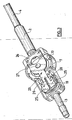
- valve 1 of the figure 1 in fact an adjustable flow regulator, is here associated with a non-return valve 2 of known type, and which will not be described.
- the fluid enters the valve via a connector 3, then passes through the valve and the non-return valve, and is finally drained by a catheter 4.
- the valve 1 is composed of a portion 5 forming a flow regulator, and a setting portion 6.
- Part 5 is essentially similar to the valve described in the document FR-A-2,746,659 supra.
- FIG. 2 the housing 7 of the valve.
- An elastic membrane 8 mounted at its periphery in the housing 7 defines in the housing an upstream chamber 9 and a downstream chamber 10.
- the membrane 8 carries at its center a washer 11 having a central opening 12.
- the housing forms in the upstream chamber a seat of known type, not shown.
- the outer edge of the membrane 8 is retained in the housing 7 simultaneously with a fastening ring 13 which covers this border.
- the ring 13 is made in one piece with three radial elastic support arms 14 carrying at their inner ends a support sleeve 15 for a rod 16 of variable section, so that the rod 16 is engaged in the opening 12 of the washer 11.
- the rod 16 and the edges of the opening 12 therefore determine a passage section for the fluid, depending on the degree of depression of the rod since its section is variable.
- Projections 17 formed in the housing 7 cooperate with complementary notches 18 formed at the periphery of the ring 13 to index the ring 13 in rotation with respect to the axis of the membrane 8 and the ring 13.
- the valve 1 further comprises a magnetic adjustment motor 19 of any known type. Once the valve is implanted, this motor allows its adjustment from the outside of the body of the patient using a suitable magnet.
- the output shaft of the motor 19 supports a plate 20 in the form of a disc.
- the plate 20 carries two pairs of radial ribs 21 and 22 oriented at 90 ° to each other.
- the two ribs 21, respectively 22, are symmetrical with respect to the axis of the plate 20.
- the ribs 22 have a height greater than that of the ribs 21 above the plane of the plate 20.
- a lever 23 has one of its ends 24 fixed to the housing 7 on the side of the portion 5 of the valve 1 opposite the magnetic motor 19.
- the other end of the lever 23 has two branches 25 in the form of pallets, the two branches being separated longitudinally by a slot 26 of a width slightly greater than that of the ribs 21 and 22.
- the lever 23 In its central part, the lever 23 cooperates with a guide and support member 27 to determine the depression of the rod 16 in the washer 11.
- the other ribs engage in the slot 26 of the lever 23.
- the magnetic motor 19 is disposed on a support plate 29 mounted by any suitable means sliding relative to the housing 7.
- the magnetic motor 19 Depending on whether the magnetic motor 19 orients the ribs 21 or the ribs 22 perpendicularly to the longitudinal direction of the lever 23, it is supported on one or the other of these ribs. It therefore more or less pushes the rod 16 into the orifice of the washer 11 and thus determines, as has been explained above, the regulating flow rate of the valve 1 among two possible flow rates.
Landscapes
- Health & Medical Sciences (AREA)
- Engineering & Computer Science (AREA)
- Biomedical Technology (AREA)
- Neurology (AREA)
- Ophthalmology & Optometry (AREA)
- Otolaryngology (AREA)
- Anesthesiology (AREA)
- Heart & Thoracic Surgery (AREA)
- Hematology (AREA)
- Life Sciences & Earth Sciences (AREA)
- Animal Behavior & Ethology (AREA)
- General Health & Medical Sciences (AREA)
- Public Health (AREA)
- Veterinary Medicine (AREA)
- Infusion, Injection, And Reservoir Apparatuses (AREA)
- External Artificial Organs (AREA)
Claims (16)
- In den Körper eines Patienten einsetzbares Ventil zur Behandlung des Wasserkopf, von dem Typ umfassend:- ein einen Hohlraum bildendes Gehäuse (7);- eine Trennmembran (8), die an ihrer Peripherie am Gehäuse angebracht ist, mit einer Öffnung (12) versehen ist und die in dem genannten Hohlraum eine obere Kammer (9) und eine untere Kammer (10) begrenzt;- wobei das genannte Gehäuse in der oberen Kammer einen Sitz für die Membran begrenzt, wobei der genannte Sitz die genannte Öffnung umgibt:- einen Stift (16) mit variablem Querschnitt, der angeordnet ist, um axial in die genannte Öffnung einzudringen;- Trägermittel (14, 15) des Stiftes;gekennzeichnet durch die Tatsache, dass es axiale Verschiebungsmittel (23) der Trägermittel des Stiftes, Motormittel (19) zum Antreiben der genannten Verschiebungsmittel umfasst, wobei die genannten Motormittel angeordnet sind, um von der Außenseite des Körpers des Patienten derart aktiviert zu werden, dass die Einstellung des Ventils auf nicht invasive Weise ermöglicht wird und wobei die genannten Trägermittel des Stiftes eine Vielzahl von radialen, elastischen Trägerarmen (14) umfassen, die an einem ersten ihrer Enden an dem genannten Gehäuse befestigt sind und einen Trägerstutzen (15) des Stiftes an ihrem anderen Ende tragen.
- Ventil gemäß Anspruch 1, in dem die genannten ersten Enden der Trägerarme fest mit einem Befestigungsring (13) verbunden sind, der am Rand der genannten Membran anliegt.
- Ventil gemäß Anspruch 1 und 2, in dem die genannten Verschiebungsmittel einen Hebel (23) umfassen, der auf dem genannten Gehäuse an einem ersten seiner Enden angebracht ist.
- Ventil gemäß Anspruch 1 bis 3, in dem die genannten Verschiebungsmittel einen Hebel (23) umfassen, der auf dem genannten Gehäuse und aufstützend auf den genannten Trägermitteln des Stiftes angebracht ist, wobei der genannte Hebel mit den Nockenmitteln (20 - 22) der genannten Motormittel zusammenwirkt.
- Ventil gemäß Anspruch 4, in dem der genannte Hebel ein an dem genannten Gehäuse befestigtes elastisches Blatt umfasst.
- Ventil gemäß Anspruch 4 und 5, in dem der genannte Hebel an einem seiner Enden auf dem Gehäuse angebracht ist, mit den genannten Nockenmitteln an seinem anderen Ende zusammenwirkt und sich auf den genannten Trägermitteln des Stiftes in seinem medianen Teil aufstützt.
- Ventil gemäß Anspruch 4 bis 6, in dem die Längsposition der Nockenmittel in der allgemeinen Richtung des Hebels einstellbar ist.
- Ventil gemäß Anspruch 4 bis 7 mit elastischen Mitteln (28) zur Anwendung des genannten Hebels auf die genannten Nockenmittel.
- Ventil gemäß Anspruch 8, in dem die genannten elastischen Mittel (28) wenigstens ein elastisches Blatt umfassen.
- Ventil gemäß der Struktur des Anspruchs 9 und des Anspruchs 2, in dem das genannte elastische Blatt aus einem einzigen Stück mit dem genannten Befestigungsring realisiert wird.
- Ventil gemäß Anspruch 10, in dem das Gehäuse und der Befestigungsring Vorsprünge (17) und komplementäre Einkerbungen (18) für die winkelförmige Indexierung des Rings im Verhältnis zum Gehäuse umfassen.
- Ventil gemäß Anspruch 1 bis 11, in dem die genannten Motormittel einen magnetischen Motor umfassen.
- Ventil gemäß Anspruch 1 bis 12, in dem die genannten Motormittel wenigstens eine motorisierte Nocke (20 - 22) umfassen, die angeordnet ist, um mit einem Nockennachlaufgerät (25) der genannten Verschiebungsmittel zusammenzuwirken.
- Ventil gemäß Anspruch 13, in dem die genannte motorisierte Nocke eine Platine (20) umfasst, die angeordnet ist, um in Rotation durch einen Motor (19) angetrieben zu werden, wobei die genannte Platine wenigstens zwei radiale Rippungen (21, 22) unterschiedlicher Höhe umfasst, die angeordnet sind, um mit dem genannten Nockenlaufgerät zusammenzuwirken.
- Ventil gemäß Anspruch 14 und Anspruch 4 bis 11, in dem die genannte Platine zwei Paare deutlich lotrechter radialer Rippungen umfasst, wobei die zwei Rippungen jedes Paares auf jeder Seite der Rotationsachse der Platine angeordnet sind und deutlich dieselbe Höhe aufweisen, die unterschiedlich von der Höhe der Rippungen des anderen Paares ist, und in dem der genannte Hebel in seinem Teil, in dem er mit der genannten Nocke zusammenwirkt, zwei Zweige (25) bildet, die jeweils mit einer der Rippungen eines der Paare der Rippungen zusammenwirken.
- Ventil gemäß Anspruch 14, das mit einem der Ansprüche 9 bis 11 verbunden ist und zwei elastische Blätter umfasst, die sich jeweils auf einen der Zweige des genannten Hebels aufstützen.
Applications Claiming Priority (2)
| Application Number | Priority Date | Filing Date | Title |
|---|---|---|---|
| FR0303057 | 2003-03-12 | ||
| FR0303057A FR2852252B1 (fr) | 2003-03-12 | 2003-03-12 | Valve implantable pour le traitement de l'hydrocephalie |
Publications (2)
| Publication Number | Publication Date |
|---|---|
| EP1457231A1 EP1457231A1 (de) | 2004-09-15 |
| EP1457231B1 true EP1457231B1 (de) | 2009-05-13 |
Family
ID=32749780
Family Applications (1)
| Application Number | Title | Priority Date | Filing Date |
|---|---|---|---|
| EP04290690A Expired - Lifetime EP1457231B1 (de) | 2003-03-12 | 2004-03-12 | Implantierbares Ventil zur Behandlung von Hydrocephalus |
Country Status (4)
| Country | Link |
|---|---|
| US (1) | US20040236264A1 (de) |
| EP (1) | EP1457231B1 (de) |
| DE (1) | DE602004021053D1 (de) |
| FR (1) | FR2852252B1 (de) |
Cited By (1)
| Publication number | Priority date | Publication date | Assignee | Title |
|---|---|---|---|---|
| WO2014040723A1 (de) | 2012-09-11 | 2014-03-20 | C.Miethke Gmbh & Co Kg | Einstellbares hydrocephalus-ventil |
Families Citing this family (2)
| Publication number | Priority date | Publication date | Assignee | Title |
|---|---|---|---|---|
| US10569065B2 (en) | 2012-09-11 | 2020-02-25 | Christoph Miethke Gmbh & Co Kg | Adjustable hydrocephalus valve |
| WO2014144703A2 (en) | 2013-03-15 | 2014-09-18 | Hakim Carlos | Externally programmable valve assembly |
Family Cites Families (8)
| Publication number | Priority date | Publication date | Assignee | Title |
|---|---|---|---|---|
| US4551128A (en) * | 1983-05-11 | 1985-11-05 | Salomon Hakim | Cerebrospinal fluid shunt valve |
| US4772257A (en) * | 1983-12-08 | 1988-09-20 | Salomon Hakim | External programmer for magnetically-adjustable cerebrospinal fluid shunt valve |
| US4676772A (en) * | 1985-12-23 | 1987-06-30 | Cordis Corporation | Adjustable implantable valve having non-invasive position indicator |
| US4781672A (en) * | 1986-10-21 | 1988-11-01 | Cordis Corporation | Three stage implantable flow control valve with improved valve closure member |
| FR2746659B1 (fr) * | 1996-03-26 | 1998-06-19 | Cordis Sa | Valve pour le traitement de l'hydrocephalie |
| US6050969A (en) * | 1998-04-17 | 2000-04-18 | Johnson & Johnson Professional, Inc. | Pressure indicator |
| JP2001104471A (ja) * | 1999-10-04 | 2001-04-17 | Seiko Instruments Inc | 圧力可変弁装置及び該弁装置の設定圧力検出装置 |
| JP3852734B2 (ja) * | 1999-12-20 | 2006-12-06 | セイコーインスツル株式会社 | 圧力可変弁装置及び該弁装置の設定圧力調整装置 |
-
2003
- 2003-03-12 FR FR0303057A patent/FR2852252B1/fr not_active Expired - Fee Related
-
2004
- 2004-03-11 US US10/798,242 patent/US20040236264A1/en not_active Abandoned
- 2004-03-12 EP EP04290690A patent/EP1457231B1/de not_active Expired - Lifetime
- 2004-03-12 DE DE602004021053T patent/DE602004021053D1/de not_active Expired - Lifetime
Cited By (3)
| Publication number | Priority date | Publication date | Assignee | Title |
|---|---|---|---|---|
| WO2014040723A1 (de) | 2012-09-11 | 2014-03-20 | C.Miethke Gmbh & Co Kg | Einstellbares hydrocephalus-ventil |
| EP3023119A2 (de) | 2012-09-11 | 2016-05-25 | Christoph Miethke Gmbh & Co. KG | Einstellbares hydrocephalus-ventil mit feder |
| EP3031489A1 (de) | 2012-09-11 | 2016-06-15 | Christoph Miethke Gmbh & Co. KG | Einstellbares hydrocephalus-ventil mit separater achse |
Also Published As
| Publication number | Publication date |
|---|---|
| DE602004021053D1 (de) | 2009-06-25 |
| EP1457231A1 (de) | 2004-09-15 |
| FR2852252A1 (fr) | 2004-09-17 |
| FR2852252B1 (fr) | 2005-07-08 |
| US20040236264A1 (en) | 2004-11-25 |
Similar Documents
| Publication | Publication Date | Title |
|---|---|---|
| EP0810944B1 (de) | Schnellspannachse für ein fahrrad | |
| EP2401509B1 (de) | Gebläseschaufeln mit zyklischer einstellung | |
| EP1887188B1 (de) | Steuervorrichtung einer Schaufel mit verstellbaren Winkel für eine Turbomachine mit zylindrischer Pleuelstange | |
| EP2139718A2 (de) | Energieaufnahmevorrichtung für einen automobilsitz sowie anordnung und sitz mit einer solchen vorrichtung | |
| CA2591770A1 (fr) | Stator de turbomachine comportant un etage d'aubes de redresseurs actionnees par une couronne rotative a centrage automatique | |
| EP2009244A1 (de) | Axiale Haltevorrichtung für Laufradschaufeln, die auf einer Rotorscheibe einer Strömungsmaschine montiert sind | |
| EP1491725B1 (de) | Lagervorrichtung für eine verstellbare Schaufel | |
| EP1457231B1 (de) | Implantierbares Ventil zur Behandlung von Hydrocephalus | |
| FR2881175A1 (fr) | Commande de reglage de distribution variable de soupapes | |
| EP0798012A1 (de) | Ventil zur Behandlung von Hydrocephalus | |
| EP1604703B1 (de) | Subkutanventil | |
| EP4267838B1 (de) | Lufteinlass für eine flugzeugantriebseinheit mit einem element zur bewegung eines beweglichen vorgelagerten teils und verfahren zur verwendung eines solchen lufteinlasses | |
| FR2744414A1 (fr) | Soupape de commande de pression pour direction assistee | |
| CA2932998A1 (fr) | Compresseur de turbomachine, en particulier de turbopropulseur ou de turboreacteur d'avion | |
| EP0014643A1 (de) | Wassereinspritzvorrichtung für Dampfbügeleisen und diesbezügliches Dampfbügeleisen | |
| EP1072762B1 (de) | Ventilbetätigungsgerät und ein mit diesem Gerät ausgerüsteter Verbrennungsmotor | |
| FR2496583A1 (fr) | Mecanisme de direction assistee | |
| EP2050491B1 (de) | Reinigungsvorrichtung durch Zentrifugieren für ein Fluid, das ein Gas und Ölpartikel enthält | |
| FR2502571A1 (fr) | Appareil de commande de direction assistee | |
| EP1445169B1 (de) | Gleitdrehlager einer verstellbaren Lenksäule eines Kraftfahrzeuges | |
| FR2503316A1 (fr) | Perfectionnements apportes aux robinets a boisseau ou tournant, notamment aux robinets a gaz | |
| WO2021032918A1 (fr) | Structure interne pour nacelle de turbomachine | |
| WO1985004928A1 (fr) | Injecteur pour turbine hydraulique | |
| FR2897120A1 (fr) | Pivot d'aube a angle de calage variable de turbomachine et dispositif de commande d'une telle aube | |
| EP0556524B1 (de) | Hubventilsteuerungsvorrichtung mit Mitteln zum Sperren der Ventildrehbewegung |
Legal Events
| Date | Code | Title | Description |
|---|---|---|---|
| PUAI | Public reference made under article 153(3) epc to a published international application that has entered the european phase |
Free format text: ORIGINAL CODE: 0009012 |
|
| AK | Designated contracting states |
Kind code of ref document: A1 Designated state(s): AT BE BG CH CY CZ DE DK EE ES FI FR GB GR HU IE IT LI LU MC NL PL PT RO SE SI SK TR |
|
| AX | Request for extension of the european patent |
Extension state: AL HR LT LV MK |
|
| 17P | Request for examination filed |
Effective date: 20041025 |
|
| AKX | Designation fees paid |
Designated state(s): CH DE FR GB LI |
|
| 17Q | First examination report despatched |
Effective date: 20071122 |
|
| GRAP | Despatch of communication of intention to grant a patent |
Free format text: ORIGINAL CODE: EPIDOSNIGR1 |
|
| GRAP | Despatch of communication of intention to grant a patent |
Free format text: ORIGINAL CODE: EPIDOSNIGR1 |
|
| GRAS | Grant fee paid |
Free format text: ORIGINAL CODE: EPIDOSNIGR3 |
|
| GRAA | (expected) grant |
Free format text: ORIGINAL CODE: 0009210 |
|
| AK | Designated contracting states |
Kind code of ref document: B1 Designated state(s): CH DE FR GB LI |
|
| REG | Reference to a national code |
Ref country code: GB Ref legal event code: FG4D Free format text: NOT ENGLISH |
|
| REG | Reference to a national code |
Ref country code: CH Ref legal event code: EP |
|
| REF | Corresponds to: |
Ref document number: 602004021053 Country of ref document: DE Date of ref document: 20090625 Kind code of ref document: P |
|
| REG | Reference to a national code |
Ref country code: CH Ref legal event code: NV Representative=s name: ABREMA AGENCE BREVET ET MARQUES, GANGUILLET |
|
| PLBE | No opposition filed within time limit |
Free format text: ORIGINAL CODE: 0009261 |
|
| STAA | Information on the status of an ep patent application or granted ep patent |
Free format text: STATUS: NO OPPOSITION FILED WITHIN TIME LIMIT |
|
| 26N | No opposition filed |
Effective date: 20100216 |
|
| REG | Reference to a national code |
Ref country code: FR Ref legal event code: PLFP Year of fee payment: 13 |
|
| REG | Reference to a national code |
Ref country code: FR Ref legal event code: PLFP Year of fee payment: 14 |
|
| REG | Reference to a national code |
Ref country code: FR Ref legal event code: PLFP Year of fee payment: 15 |
|
| REG | Reference to a national code |
Ref country code: CH Ref legal event code: PFUS Owner name: INTEGRA NEUROSCIENCES IMPLANTS (FRANCE) SA, FR Free format text: FORMER OWNER: INTEGRA NEUROSCIENCES IMPLANTS (FRANCE) SA, FR |
|
| PGFP | Annual fee paid to national office [announced via postgrant information from national office to epo] |
Ref country code: FR Payment date: 20210325 Year of fee payment: 18 Ref country code: CH Payment date: 20210324 Year of fee payment: 18 |
|
| PGFP | Annual fee paid to national office [announced via postgrant information from national office to epo] |
Ref country code: DE Payment date: 20210323 Year of fee payment: 18 Ref country code: GB Payment date: 20210324 Year of fee payment: 18 |
|
| REG | Reference to a national code |
Ref country code: DE Ref legal event code: R119 Ref document number: 602004021053 Country of ref document: DE |
|
| REG | Reference to a national code |
Ref country code: CH Ref legal event code: PL |
|
| GBPC | Gb: european patent ceased through non-payment of renewal fee |
Effective date: 20220312 |
|
| PG25 | Lapsed in a contracting state [announced via postgrant information from national office to epo] |
Ref country code: LI Free format text: LAPSE BECAUSE OF NON-PAYMENT OF DUE FEES Effective date: 20220331 Ref country code: GB Free format text: LAPSE BECAUSE OF NON-PAYMENT OF DUE FEES Effective date: 20220312 Ref country code: FR Free format text: LAPSE BECAUSE OF NON-PAYMENT OF DUE FEES Effective date: 20220331 Ref country code: DE Free format text: LAPSE BECAUSE OF NON-PAYMENT OF DUE FEES Effective date: 20221001 Ref country code: CH Free format text: LAPSE BECAUSE OF NON-PAYMENT OF DUE FEES Effective date: 20220331 |