EP1457603A9 - Verfahren zur Herstellung einer Erdböschung und danach hergestellte Erdböschung - Google Patents
Verfahren zur Herstellung einer Erdböschung und danach hergestellte Erdböschung Download PDFInfo
- Publication number
- EP1457603A9 EP1457603A9 EP20040101037 EP04101037A EP1457603A9 EP 1457603 A9 EP1457603 A9 EP 1457603A9 EP 20040101037 EP20040101037 EP 20040101037 EP 04101037 A EP04101037 A EP 04101037A EP 1457603 A9 EP1457603 A9 EP 1457603A9
- Authority
- EP
- European Patent Office
- Prior art keywords
- spacers
- reinforcement
- core area
- area
- front elements
- Prior art date
- Legal status (The legal status is an assumption and is not a legal conclusion. Google has not performed a legal analysis and makes no representation as to the accuracy of the status listed.)
- Granted
Links
Images


Classifications
-
- E—FIXED CONSTRUCTIONS
- E02—HYDRAULIC ENGINEERING; FOUNDATIONS; SOIL SHIFTING
- E02D—FOUNDATIONS; EXCAVATIONS; EMBANKMENTS; UNDERGROUND OR UNDERWATER STRUCTURES
- E02D29/00—Independent underground or underwater structures; Retaining walls
- E02D29/02—Retaining or protecting walls
- E02D29/0225—Retaining or protecting walls comprising retention means in the backfill
- E02D29/0241—Retaining or protecting walls comprising retention means in the backfill the retention means being reinforced earth elements
Definitions
- the invention relates to a method for producing a Earth embankment in which a load-bearing and solidified layer Core area is built up, which is composed of several layers Filling floor, of a substantially horizontal section per layer, a bottom-up portion and one folded back section of a flexible reinforcement sheet enclosed and compacted, and at a distance from the compacted Core area with stiff, large front element using spacers be attached so that between the front elements and the Core area creates a free space from bottom to top, that can be filled.
- EP-1 054 110 describes such a method for producing a Earth slope known.
- Soundproof walls can also be made using this known method erect that can be planted on both sides and that according to the described procedures are set up.
- the filling layers are there ever narrower towards the top, so the side walls of the wall on both sides get an inclination of about 60 ° to 70 °.
- the individual layers of filling soil are shaken or Vibratory rollers compacted before the next higher filler layer is applied.
- the flexible reinforcement meshes are designed as geogrids with a mesh size of 20 mm x 20 mm to 50 mm x 50 mm.
- the Thread strands of the geogrid are covered with a polymer protective layer equipped.
- Warp strands and weft strands can also be made Plastic geogrids are used.
- the rod-shaped and over the solidified core area around 20, 30 or 40 cm protruding spacers during the construction of the core area between the filling floor layers inserted It is difficult to arrange the spacers so that they are too maintain their position when compacting the higher layers of filling soil. Also cause the protruding rod-shaped spacers for the Construction workers at risk of injury.
- the invention lies in the The task is to develop the method in such a way that it is precise Attaching the spacers facilitates and quick assembly of a Front or visible side of an earth embankment is possible.
- This object is achieved in that during the Production of the solidified core area or thereafter behind that from below at least upward sections of the reinforcement webs some filler floor layers inserted rod-shaped, load-distributing elements or be inserted and that the spacers, on their the Ends facing the core region are provided with a hook with which the spacers through an opening in the reinforcement webs be hooked onto the rod-shaped elements.
- the Spacers at the end facing the core area have a substantially right-angled part that can be hooked serves in a reinforcement track and the load distribution and with which the Spacers through openings in the bottom to top Sections of the reinforcement web gripping the reinforcement webs of the Filling floor layers are attached.
- the reinforcement sheets are made of synthetic fabrics, in particular high-strength polyester fabrics, or, because of the better interlocking with the filling floor, formed by geogrid tracks, and the large-scale Rigid front elements are steel or plastic mesh or mesh reinforced concrete slabs.
- Anchoring the spacers to the reinforcement webs Filling floor layers has the advantage that the spacers are held reliably become. Furthermore, less material is used for the production of the spacers needed. Furthermore, the spacers and the load distributing Components be designed so that they only after the compressed Core area to be attached.
- the load-distributing bars can be behind when building up the filling floor layers the bottom-up portion of the Reinforcement sheet to be attached. These load-distributing bars can but also after producing the compacted core area behind the Reinforcement track of the individual layers of filling floor inserted or be driven in.
- the bars distribute the one exerted by the spacer Load on the vertical threads of a reinforcement sheet forming fabric web or geogrid web.
- the reinforcement tracks are formed by geogrid tracks, then allow the at least 20 mm x 20 mm meshes of the Geogrid tracks as well as a local extensibility of the Geogrid thread strands that the load-distributing rods or the parts of the spacers that are angled at right angles even after manufacture of the solidified core area behind the front of the geogrid tracks can be brought.
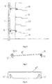
- Fig. 1 shows a cross section of an earth embankment, the composed of a natural, existing earth embankment 3, before the layered geotextile reinforced core area 1 was built and in front of which there is an outer skin area 2.
- the solidified core area 1 is composed in this example five layers 21-25 filling floor 4, each layer on three sides by a flexible Reinforcement sheet 5 is enclosed.
- the reinforcement web 5 each Fill floor layer 21-25 has a substantially horizontal lower one Section, a front, from bottom to top, in essential vertical section 6 and a folded back upper Section.
- Each filling bottom layer 21-25 is by means of vibratory rollers or The like compacted before the next higher layer built up becomes.
- To achieve a vertical section 6 of the Reinforcement sheet 5 is one for each layer before filling the floor 4 preferably vertical formwork attached. Has the floor to be filled 4 reaches its layer thickness, the upper section of the Reinforcement sheet folded back and the filled soil compacted.
- the flexible reinforcement membrane and the formwork of the next layer are attached so that the slope is the desired slope receives. This creates levels that are larger the smaller the Slope angle is horizontal.
- the spacers 8 are made of galvanized or not galvanized steel wire and have a length of about 20 to 70 cm long straight section and in the embodiment of FIGS. 1, 2 and 5 U-shaped hooks 12 or 12 'at both ends.
- the spacer 8 1, 2 and 5 serves to carry out the method according to Claim 1, while the spacers 8 'for performing the Process according to claim 2 are determined.
- the spacers 8 shown in FIGS. 1 and 5 have at both ends U-shaped hook 12 by bending an initially straight rod are formed by 180 °.
- a hook 12 engages around the load-distributing rod 15, while the other hook 12 stiffens a horizontal bar 16 Grid mat 7 encompasses.
- the rigid grid mat 7 can be a steel mesh mat or else also be made of plastic. Consists of the grid mat Steel wire, then it should be made corrosion-resistant to Example by galvanizing or by a plastic coating.
- the spacer 8 shown in FIG. 2 also has at both ends U-shaped hooks 12 '. These are open at the bottom so that they are from above over the load-distributing rod 15 and a horizontal rod 16 one Lattice mat 7 are slipped and the lattice mat 7 with tensile and pressure resistant connect the geogrid tracks 5 of the solidified core area 1.
- a thin fleece layer 9 is arranged behind the rigid grid mat 7, then this can easily penetrate through the spacers 8,8 ' become. Is a rootable tissue on the rigid mesh mat 7 attached, then can be used to attach the spacers 8,8 ' necessary holes are cut.
- the attachment of the rigid mesh mat 7 to the spacers 8 can in done in a known manner.
- the stiff, large-area front elements 7 are reinforced Concrete slabs or concrete slabs formed, the bracket 17 on its back or have loops attached to the reinforcement of the concrete slab are connected and into which the spacers 8 can be hooked.
- the spacer 8 "according to FIG. 7 is expedient and can be easily hooked on if the front elements 7 are formed by large-mesh lattice mats.
- the Hook 12 ' may be configured to rest on the horizontal bars 16 engage a grid mat when hooking on.
- the spacers 8 "and 8" 'according to FIGS. 7 and 8 can tensile and compressive forces transfer.
- the spacers 8 "'and 8" “of FIGS. 8 and 9 show that they are not only from round steel, but also from flat steel.
- the spacer 8 "" can only because of the inwardly open hook Absorb tensile forces. These spacers 8 "" are useful if the Front elements 7 already by spacing blocks at a distance from the Front sides of the filling floor layers are kept.
Landscapes
- Engineering & Computer Science (AREA)
- Environmental & Geological Engineering (AREA)
- Life Sciences & Earth Sciences (AREA)
- General Life Sciences & Earth Sciences (AREA)
- Mining & Mineral Resources (AREA)
- Paleontology (AREA)
- Civil Engineering (AREA)
- General Engineering & Computer Science (AREA)
- Structural Engineering (AREA)
- Pit Excavations, Shoring, Fill Or Stabilisation Of Slopes (AREA)
- Investigation Of Foundation Soil And Reinforcement Of Foundation Soil By Compacting Or Drainage (AREA)
Abstract
Description
- Fig. 1
- einen Querschnitt durch eine erfindungsgemäß hergestellte Böschung mit begrünbarer Sichtfläche,
- Fig. 2
- eine vergrößerte Darstellung eines Abstandhalters, der einen lastverteilenden Stab mit einem Stab eines von einer Gittermatte gebildeten steifen großflächigen Frontelements verbindet,
- Fig. 3
- eine perspektivische Ansicht eines Abstandhalters, der hinter eine von einer Geogitterbahn gebildeten Bewehrungsbahn greift,
- Fig. 4
- eine perspektivische Ansicht eines Abstandhalters mit gegenüber Fig. 3 veränderten Haken,
- Fig. 5
- eine vergrößerte Darstellung eines Abstandhalters gemäß Fig. 1
- Fig. 6
- einen schematischen Querschnitt durch eine Böschung mit einer Sichtfläche aus Betonplatten,
- Fig. 7 - 9
- Ansichten unterschiedlicher Abstandhalter.
- 1
- verfestigter Kernbereich
- 2
- Außenhautbereich
- 3
- natürliche Erdböschung
- 4
- Füllboden (verdichtet)
- 5
- Bewehrungsbahn aus Synthetikgewebe oder Geogitter
- 6
- Frontseite der Füllbodenlagen
- 7
- steifes großflächiges Frontelement, Betonplatte oder Gittermatte
- 8
- Abstandhalter
- 8',8"
- Abstandhalter
- 8"',8""
- Abstandhalter
- 9
- durchwurzelbare dünne Vliesmatte oder Gittergewebe
- 10
- Vegetationsboden
- 11
- abgewinkeltes Teil des Abstandhalters 8'
- 12
- vertikal offener Haken
- 12'
- horizontal offener Haken
- 13
- Fadenstrang horizontal
- 14
- Fadenstrang vertikal
- 15
- lastverteilender Stab
- 16
- horizontaler Stab einer steifen Gittermatte 7
- 17
- Bügel
- 21
- unterste Füllbodenlage
- 22
- zweite Füllbodenlage
- 23
- dritte Füllbodenlage
- 24
- vierte Füllbodenlage
- 25
- fünfte Füllbodenlage
Claims (16)
- Verfahren zur Herstellung einer Erdböschung, bei dem schichtweise ein tragender und verfestigter Kernbereich (1) aufgebaut wird, der sich zusammensetzt aus mehreren Lagen (21-25) Füllboden (4), der je Lage von einem im wesentlichen horizontalen Abschnitt, einem von unten nach oben sich erstreckenden Abschnitt (6) und einem zurückgefalteten Abschnitt einer flexiblen Bewehrungsbahn (5) umschlossen und verdichtet wird, und im Abstand von dem verdichteten Kernbereich (1) mittels Abstandhaltern (8) steife, großflächige Frontelemente befestigt werden, so daß zwischen den Frontelementen (7) und dem Kernbereich (1) ein von unten bis oben durchgehender freier Raum entsteht, der verfüllt werden kann, dadurch gekennzeichnet, daß während der Herstellung des verfestigten Kernbereichs (1) oder danach hinter die von unten nach oben verlaufenden Abschnitte (6) der Bewehrungsbahnen (5) zumindest einiger Füllbodenlagen (21 - 25) stabförmige, lastverteilende Elemente (15) eingelegt oder eingeschoben werden und daß die Abstandhalter (8,8",8"') ihren dem Kernbereich (1) zugewandten Ende mit einem Haken (12,12') versehen sind, mit dem die Abstandhalter (8) durch eine Öffnung in den Bewehrungsbahnen (5) hindurch an die stabförmigen Elemente (15) angehakt werden.
- Verfahren zur Herstellung einer Erdböschung, bei dem schichtweise ein tragender und verfestigter Kernbereich (1) aufgebaut wird, der sich zusammensetzt aus mehreren Lagen (21-25) Füllboden (4), der je Lage von einem im wesentlichen horizontalen Abschnitt, einem von unten nach oben sich erstreckenden Abschnitt (6) und einem zurückgefalteten Abschnitt einer flexiblen Bewehrungsbahn (5) umschlossen und verdichtet wird, und im Abstand von dem verdichteten Kernbereich (1) mittels Abstandhaltern (8) steife, großflächige Frontelemente befestigt werden, so daß zwischen den Frontelementen (7) und dem Kernbereich (1) ein von unten bis oben durchgehender freier Raum entsteht, der verfüllt werden kann, dadurch gekennzeichnet, daß der Abstandhalter (8') an dem dem Kernbereich zugewandten Ende ein im wesentlichen rechtwinklig abgewinkeltes Teil (11) aufweist, das zum Einhaken in eine Bewehrungsbahn (5) und der Lastverteilung dient und mit dem die Abstandhalter (8') durch Öffnungen in den von unten nach oben verlaufenden Abschnitten der Bewehrungsbahn (5) greifend an Bewehrungsbahnen (5) mindestens einiger Füllbodenlagen (21 - 25) befestigt werden.
- Verfahren nach Anspruch 1 oder 2, dadurch gekennzeichnet, daß die Abstandhalter (8,8',8",8"',8"") an beiden Enden Haken (11,12,12') aufweisen, mit denen sie einerseits an die Bewehrungsbahnen (5) oder über die lastverteilende Stäbe (15) einhakbar sind und andererseits über Stäbe (16), Bügel oder Schlaufen der großflächigen Frontelemente (7) hakbar sind.
- Verfahren nach Anspruch 1 oder 2, dadurch gekennzeichnet, daß die Bewehrungsbahnen (5) Geogitterbahnen, insbesondere aus hochmodulen Polyestergarnen, sind.
- Verfahren nach Anspruch 1 oder 2, dadurch gekennzeichnet, daß der Bewehrungsbahnen (5) Synthetikgewebe sind, in das die Öffnungen für den Durchlaß der Abstandhalter (8,8',8",8"", 8"") eingeschnitten oder eingebrannt werden.
- Verfahren nach einem der Ansprüche 1 bis 4, dadurch gekennzeichnet, daß die steifen großflächigen Frontelemente (7) Gittermatten aus Stahl, insbesondere verzinkte Baustahlgittermatten sind.
- Verfahren nach einem der Ansprüche 1 bis 6, dadurch gekennzeichnet, daß die steifen großflächigen Frontelemente (7) bewehrte Betonplatten sind, die auf ihrer Rückseite mit der Bewehrung in Verbindung stehende Schlaufen oder Bügel (17) aufweisen.
- Erdböschung mit einem schichtweise aufgebauten, verfestigten Kernbereich (1), der sich zusammensetzt aus mehreren Lagen (21-25) Füllboden (4), der je Lage zumindest frontseitig von einer Bewehrungsbahn (5) an drei Seiten umschlossen und verdichtet ist, im Abstand von diesem Kernbereich (1) mittels Abstandhaltern (8) steife, großflächige Frontelemente (7) befestigt ist, hergestellt nach dem Verfahren gemäß Anspruch 1, dadurch gekennzeichnet, daß im Bereich der von unten nach oben verlaufenden Abschnitte (6) der Bewehrungsbahnen (5) mindestens einiger Füllbodenlagen (21-25) hinter der Bewehrungsbahn (5) lastverteilende Stäbe (15) angeordnet sind und im Abstand von dem Kernbereich (1) die steifen Frontelemente (7) von Abstandhaltern (8) gehalten sind, die an beiden Enden Haken (12,12') aufweisen, von denen die einen über die lastverteilenden Stäbe (15) greifen und die anderen Haken (12,12') Stäbe (16), Schlaufen oder Bügel (17) der steifen großflächigen Frontelemente (7) umgreifen.
- Erdböschung mit einem schichtweise aufgebauten, verfestigten Kernbereich (1), der sich zusammensetzt aus mehreren Lagen (21-25) Füllboden (4), der je Lage zumindest frontseitig von einer Bewehrungsbahn (5) an drei Seiten umschlossen und verdichtet ist, im Abstand von diesem Kernbereich (1) mittels Abstandhaltern (8) steife, großflächige Frontelemente (7) befestigt sind, hergestellt nach dem Verfahren gemäß Anspruch 2, dadurch gekennzeichnet, daß die Abstandhalter (8') an ihren dem Kernbereich (1) zugewandten Ende im wesentlichen rechtwinklig abgewinkelte, lastverteilende gerade Haken (11) aufweisen, die im Bereich der von unten nach oben verlaufenden Abschnitte (6) der Bewehrungsbahnen (5) mindestens einiger Füllbodenlagen (21-25) hinter einer Frontseite (6) einer Bewehrungsbahn (5) eingehakt sind und am anderen Ende der Abstandhalter (8') die Frontelemente (7) befestigt sind.
- Erdböschung nach Anspruch 9, dadurch gekennzeichnet, daß die Abstandhalter (8') an ihren den Frontelementen (7) zugewandten Enden Haken (12,12') aufweisen, welche Stäbe (16) von Geogittermatten, Bügeln (17) oder Schlaufen an der Rückseite von Betonplatten umgreifen.
- Erdböschung nach einem der Ansprüche 8 bis 10, dadurch gekennzeichnet, daß die Bewehrungsbahnen (5) Geogitterbahnen sind.
- Erdböschung nach einem der Ansprüche 8 bis 10, dadurch gekennzeichnet, daß die Bewehrungsbahnen (5) dichte Synthetikgewebe sind.
- Erdböschung nach einem der Ansprüche 8 bis 12, dadurch gekennzeichnet, daß die Frontelemente (5) großflächige steife Gittermatten sind.
- Erdböschung nach einem der Ansprüche 8 bis 12, dadurch gekennzeichnet, daß die großflächigen steifen Formelemente (5) bewehrte Betonplatten oder -tafeln sind.
- Erdböschung nach einem der Ansprüche 8 bis 14, dadurch gekennzeichnet, daß die Abstandhalter (8,8",8"',8"") an beiden Enden Haken (12,12') aufweisen.
- Erdböschung nach Anspruch 14, dadurch gekennzeichnet, daß die Haken (12') der Abstandhalter (8) U-förmig und horizontal insbesondere unten offen sind.
Applications Claiming Priority (4)
| Application Number | Priority Date | Filing Date | Title |
|---|---|---|---|
| DE2003111597 DE10311597A1 (de) | 2003-03-14 | 2003-03-14 | Verfahren zur Herstellung einer Erdböschung und danach hergestellte Erdböschung |
| DE10311597 | 2003-03-14 | ||
| DE10328325 | 2003-06-24 | ||
| DE10328325 | 2003-06-24 |
Publications (4)
| Publication Number | Publication Date |
|---|---|
| EP1457603A2 EP1457603A2 (de) | 2004-09-15 |
| EP1457603A9 true EP1457603A9 (de) | 2004-11-10 |
| EP1457603A3 EP1457603A3 (de) | 2005-11-30 |
| EP1457603B1 EP1457603B1 (de) | 2008-07-23 |
Family
ID=32773180
Family Applications (1)
| Application Number | Title | Priority Date | Filing Date |
|---|---|---|---|
| EP20040101037 Expired - Lifetime EP1457603B1 (de) | 2003-03-14 | 2004-03-12 | Verfahren zur Herstellung einer Erdböschung und danach hergestellte Erdböschung |
Country Status (3)
| Country | Link |
|---|---|
| EP (1) | EP1457603B1 (de) |
| DE (1) | DE502004007643D1 (de) |
| ES (1) | ES2311134T3 (de) |
Families Citing this family (1)
| Publication number | Priority date | Publication date | Assignee | Title |
|---|---|---|---|---|
| CN115478516B (zh) * | 2022-08-22 | 2024-11-26 | 中国港湾工程有限责任公司 | 排洪渠结构 |
Family Cites Families (7)
| Publication number | Priority date | Publication date | Assignee | Title |
|---|---|---|---|---|
| JPH05247955A (ja) * | 1992-03-06 | 1993-09-24 | Taisei Corp | 擁壁の施工方法 |
| WO1998033987A1 (de) * | 1997-01-30 | 1998-08-06 | Josef Krismer | Gitterkonstruktion zum hinterfüllen mit schüttmaterial |
| JPH10317381A (ja) * | 1997-05-16 | 1998-12-02 | Tenryu Ind Co Ltd | 擁壁による法面の保護構造及びその構築方法 |
| GB2334739A (en) * | 1998-02-25 | 1999-09-01 | Netlon Ltd | A geoengineering construction |
| US6186703B1 (en) * | 1998-03-12 | 2001-02-13 | Shaw Technologies | Mechanical interlocking means for retaining wall |
| US5975810A (en) * | 1998-04-01 | 1999-11-02 | Taylor; Thomas P. | Geo-grid anchor |
| DE19922670A1 (de) | 1999-05-18 | 2000-11-23 | Huesker Synthetic Gmbh & Co | Verfahren zur Herstellung einer begrünbaren Außenhaut einer Erdböschung |
-
2004
- 2004-03-12 EP EP20040101037 patent/EP1457603B1/de not_active Expired - Lifetime
- 2004-03-12 ES ES04101037T patent/ES2311134T3/es not_active Expired - Lifetime
- 2004-03-12 DE DE200450007643 patent/DE502004007643D1/de not_active Expired - Lifetime
Also Published As
| Publication number | Publication date |
|---|---|
| DE502004007643D1 (de) | 2008-09-04 |
| EP1457603B1 (de) | 2008-07-23 |
| ES2311134T3 (es) | 2009-02-01 |
| EP1457603A2 (de) | 2004-09-15 |
| EP1457603A3 (de) | 2005-11-30 |
Similar Documents
| Publication | Publication Date | Title |
|---|---|---|
| DE2431871C3 (de) | Verfahren und Düsenplatte zur Herstellung einer elastischen Mattenbahn | |
| EP0197000B1 (de) | Element zum Erstellen begrünbarer Steilböschungen | |
| EP0979329A1 (de) | Drahtgeflecht für einen steinschlagschutz oder für die sicherung einer erdoberflächenschicht, sowie ein verfahren und eine vorrichtung zu dessen herstellung | |
| DE4024622C1 (de) | ||
| WO1995006783A2 (de) | Element für bauwerke, insbesondere für begrünbare stütz- oder schallschutzbauten, mit bauteilsatz und herstellungsverfahren | |
| EP3266951B1 (de) | Verbundbauteil mit flächigen betonfertigteilen | |
| DE2344178C2 (de) | Senkstück mit festem Ballast | |
| EP0051101B1 (de) | Zementplatte, sowie Verfahren und Vorrichtung zu deren Herstellung | |
| EP0004364B1 (de) | Verlegeeinheit aus Beton-Pflastersteinen | |
| EP1054110B1 (de) | Verfahren zur Herstellung einer begrünbaren Aussenhaut einer Erdböschung | |
| EP0774026A1 (de) | Haltevorrichtung für eine begrünbare verkleidung einer steilen wand, sowie verfahren zu ihrer herstellung | |
| DE69403349T2 (de) | Blockmatratze zum Schutz von Hängen, Böschungen und dergleichen | |
| DE4130768C1 (en) | Metal reinforcement caging for hardcore under roads - uses pre-tensioned mesh under hardcore which is then tensioned and joined over laid hardcore. | |
| EP1457603B1 (de) | Verfahren zur Herstellung einer Erdböschung und danach hergestellte Erdböschung | |
| DE10311597A1 (de) | Verfahren zur Herstellung einer Erdböschung und danach hergestellte Erdböschung | |
| EP1121493B1 (de) | Am erdreich angebaute erdkonstruktion mit steiler front und verfahren zur erstellung dieser erdkonstruktion | |
| DE60318137T2 (de) | Hangsicherung mit bewehrter Erde | |
| DE102012205484A1 (de) | Böschungsbauwerk | |
| DE8326632U1 (de) | Gittersatz zur Bildung einer Böschungsbefestigung | |
| DE19643084A1 (de) | Zellenbauwerk mit Erd- oder Gesteinsfüllung und Verfahren zu dessen Herstellung | |
| DE102019114470B4 (de) | Böschungsbauwerk | |
| DE4126657C1 (en) | Vegetative sound barrier with longitudinal walls - has each wall of longitudinal elements with vertical, tightly packed willow braches | |
| DE102004038299B4 (de) | Matte zum Begrünen von Böschungen oder dergleichen, Deckwerkselement als Erosionsschutz und zum Begrünen von Böschungen, Verfahren zur Herstellung des Deckwerkselements und Vorrichtung des Verfahrens | |
| DD296136A5 (de) | Vorgefertigter hangstein fuer den aufbau von stuetzbauwerken | |
| EP2175079B1 (de) | Verfahren zum Bilden einer biegesteifen Eckbewehrung für den Stahlbetonbau, Bewehrungselement sowie biegesteife Eckbewehrung |
Legal Events
| Date | Code | Title | Description |
|---|---|---|---|
| PUAI | Public reference made under article 153(3) epc to a published international application that has entered the european phase |
Free format text: ORIGINAL CODE: 0009012 |
|
| AK | Designated contracting states |
Kind code of ref document: A2 Designated state(s): AT BE BG CH CY CZ DE DK EE ES FI FR GB GR HU IE IT LI LU MC NL PL PT RO SE SI SK TR |
|
| AX | Request for extension of the european patent |
Extension state: AL LT LV MK |
|
| RIN1 | Information on inventor provided before grant (corrected) |
Inventor name: DIMITER, ALEXIEW, DR. |
|
| RIN1 | Information on inventor provided before grant (corrected) |
Inventor name: ALEXIEW, DIMITER, DR. |
|
| PUAL | Search report despatched |
Free format text: ORIGINAL CODE: 0009013 |
|
| AK | Designated contracting states |
Kind code of ref document: A3 Designated state(s): AT BE BG CH CY CZ DE DK EE ES FI FR GB GR HU IE IT LI LU MC NL PL PT RO SE SI SK TR |
|
| AX | Request for extension of the european patent |
Extension state: AL LT LV MK |
|
| 17P | Request for examination filed |
Effective date: 20060411 |
|
| AKX | Designation fees paid |
Designated state(s): DE ES |
|
| GRAP | Despatch of communication of intention to grant a patent |
Free format text: ORIGINAL CODE: EPIDOSNIGR1 |
|
| GRAS | Grant fee paid |
Free format text: ORIGINAL CODE: EPIDOSNIGR3 |
|
| GRAA | (expected) grant |
Free format text: ORIGINAL CODE: 0009210 |
|
| AK | Designated contracting states |
Kind code of ref document: B1 Designated state(s): DE ES |
|
| REF | Corresponds to: |
Ref document number: 502004007643 Country of ref document: DE Date of ref document: 20080904 Kind code of ref document: P |
|
| REG | Reference to a national code |
Ref country code: ES Ref legal event code: FG2A Ref document number: 2311134 Country of ref document: ES Kind code of ref document: T3 |
|
| PLBE | No opposition filed within time limit |
Free format text: ORIGINAL CODE: 0009261 |
|
| STAA | Information on the status of an ep patent application or granted ep patent |
Free format text: STATUS: NO OPPOSITION FILED WITHIN TIME LIMIT |
|
| 26N | No opposition filed |
Effective date: 20090424 |
|
| PGFP | Annual fee paid to national office [announced via postgrant information from national office to epo] |
Ref country code: DE Payment date: 20200525 Year of fee payment: 17 Ref country code: ES Payment date: 20200421 Year of fee payment: 17 |
|
| REG | Reference to a national code |
Ref country code: DE Ref legal event code: R119 Ref document number: 502004007643 Country of ref document: DE |
|
| PG25 | Lapsed in a contracting state [announced via postgrant information from national office to epo] |
Ref country code: DE Free format text: LAPSE BECAUSE OF NON-PAYMENT OF DUE FEES Effective date: 20211001 |
|
| REG | Reference to a national code |
Ref country code: ES Ref legal event code: FD2A Effective date: 20220523 |
|
| PG25 | Lapsed in a contracting state [announced via postgrant information from national office to epo] |
Ref country code: ES Free format text: LAPSE BECAUSE OF NON-PAYMENT OF DUE FEES Effective date: 20210313 |