EP1457629B1 - Dispositif pour la fixation et/ou la connexion rotative d' éléments de porte et/ou de paroi - Google Patents
Dispositif pour la fixation et/ou la connexion rotative d' éléments de porte et/ou de paroi Download PDFInfo
- Publication number
- EP1457629B1 EP1457629B1 EP04090023A EP04090023A EP1457629B1 EP 1457629 B1 EP1457629 B1 EP 1457629B1 EP 04090023 A EP04090023 A EP 04090023A EP 04090023 A EP04090023 A EP 04090023A EP 1457629 B1 EP1457629 B1 EP 1457629B1
- Authority
- EP
- European Patent Office
- Prior art keywords
- hinge
- door
- collar
- screw
- separating means
- Prior art date
- Legal status (The legal status is an assumption and is not a legal conclusion. Google has not performed a legal analysis and makes no representation as to the accuracy of the status listed.)
- Expired - Lifetime
Links
Images


Classifications
-
- E—FIXED CONSTRUCTIONS
- E05—LOCKS; KEYS; WINDOW OR DOOR FITTINGS; SAFES
- E05D—HINGES OR SUSPENSION DEVICES FOR DOORS, WINDOWS OR WINGS
- E05D5/00—Construction of single parts, e.g. the parts for attachment
- E05D5/02—Parts for attachment, e.g. flaps
- E05D5/0246—Parts for attachment, e.g. flaps for attachment to glass panels
-
- E—FIXED CONSTRUCTIONS
- E05—LOCKS; KEYS; WINDOW OR DOOR FITTINGS; SAFES
- E05D—HINGES OR SUSPENSION DEVICES FOR DOORS, WINDOWS OR WINGS
- E05D7/00—Hinges or pivots of special construction
- E05D7/04—Hinges adjustable relative to the wing or the frame
- E05D7/0415—Hinges adjustable relative to the wing or the frame with adjusting drive means
- E05D7/0423—Screw-and-nut mechanisms
-
- E—FIXED CONSTRUCTIONS
- E05—LOCKS; KEYS; WINDOW OR DOOR FITTINGS; SAFES
- E05D—HINGES OR SUSPENSION DEVICES FOR DOORS, WINDOWS OR WINGS
- E05D7/00—Hinges or pivots of special construction
- E05D7/04—Hinges adjustable relative to the wing or the frame
- E05D2007/0469—Hinges adjustable relative to the wing or the frame in an axial direction
-
- E—FIXED CONSTRUCTIONS
- E05—LOCKS; KEYS; WINDOW OR DOOR FITTINGS; SAFES
- E05D—HINGES OR SUSPENSION DEVICES FOR DOORS, WINDOWS OR WINGS
- E05D7/00—Hinges or pivots of special construction
- E05D7/04—Hinges adjustable relative to the wing or the frame
- E05D2007/0476—Pocket hinges
-
- E—FIXED CONSTRUCTIONS
- E05—LOCKS; KEYS; WINDOW OR DOOR FITTINGS; SAFES
- E05D—HINGES OR SUSPENSION DEVICES FOR DOORS, WINDOWS OR WINGS
- E05D7/00—Hinges or pivots of special construction
- E05D7/04—Hinges adjustable relative to the wing or the frame
- E05D2007/0484—Hinges adjustable relative to the wing or the frame in a radial direction
-
- E—FIXED CONSTRUCTIONS
- E05—LOCKS; KEYS; WINDOW OR DOOR FITTINGS; SAFES
- E05Y—INDEXING SCHEME ASSOCIATED WITH SUBCLASSES E05D AND E05F, RELATING TO CONSTRUCTION ELEMENTS, ELECTRIC CONTROL, POWER SUPPLY, POWER SIGNAL OR TRANSMISSION, USER INTERFACES, MOUNTING OR COUPLING, DETAILS, ACCESSORIES, AUXILIARY OPERATIONS NOT OTHERWISE PROVIDED FOR, APPLICATION THEREOF
- E05Y2600/00—Mounting or coupling arrangements for elements provided for in this subclass
- E05Y2600/50—Mounting methods; Positioning
- E05Y2600/52—Toolless
- E05Y2600/526—Gluing or cementing
-
- E—FIXED CONSTRUCTIONS
- E05—LOCKS; KEYS; WINDOW OR DOOR FITTINGS; SAFES
- E05Y—INDEXING SCHEME ASSOCIATED WITH SUBCLASSES E05D AND E05F, RELATING TO CONSTRUCTION ELEMENTS, ELECTRIC CONTROL, POWER SUPPLY, POWER SIGNAL OR TRANSMISSION, USER INTERFACES, MOUNTING OR COUPLING, DETAILS, ACCESSORIES, AUXILIARY OPERATIONS NOT OTHERWISE PROVIDED FOR, APPLICATION THEREOF
- E05Y2800/00—Details, accessories and auxiliary operations not otherwise provided for
- E05Y2800/67—Materials; Strength alteration thereof
- E05Y2800/672—Glass
-
- E—FIXED CONSTRUCTIONS
- E05—LOCKS; KEYS; WINDOW OR DOOR FITTINGS; SAFES
- E05Y—INDEXING SCHEME ASSOCIATED WITH SUBCLASSES E05D AND E05F, RELATING TO CONSTRUCTION ELEMENTS, ELECTRIC CONTROL, POWER SUPPLY, POWER SIGNAL OR TRANSMISSION, USER INTERFACES, MOUNTING OR COUPLING, DETAILS, ACCESSORIES, AUXILIARY OPERATIONS NOT OTHERWISE PROVIDED FOR, APPLICATION THEREOF
- E05Y2900/00—Application of doors, windows, wings or fittings thereof
- E05Y2900/10—Application of doors, windows, wings or fittings thereof for buildings or parts thereof
- E05Y2900/114—Application of doors, windows, wings or fittings thereof for buildings or parts thereof for showers
Definitions
- the invention relates to a device for attachment and / or rotatable connection of door and / or wall elements, in particular a glass door on or with a wall portion on which an angle with Hinge flap or a hinge with mutually movable hinge tabs force and are arranged in a form-fitting manner.
- Hinge straps with adjusting and clamping elements are known from a variety of publications.
- the hinge element provided as a receiving part is either screwed to the door or wall element or glued to it in a positive and non-positive manner.
- From DE 295 16 023 U1 a hinge for attaching a glass door to an adjacent element is known.
- the hinge part which can be mounted on the glass element, is adhesively bonded to the glass element in a positive and positive manner.
- the object of the invention is therefore to develop a device of the type mentioned above, which allows a simplified one-handed adjustment and which can be used independently of the material and also with low production costs and tool insert, both a screw - and an adhesive connection allowed. According to the invention, this object is solved by the features of claim 1.
- Advantageous embodiments of the invention are contained in the accompanying claims 2 to 13. Accordingly, the invention includes a device for fastening and / or rotatable connection of door and / or wall elements, in particular a glass door on or with a wall portion on which an angle with hinge strap or a hinge with mutually movable hinge tabs are force and positively arranged and means for horizontal and vertical adjustment are provided.
- an intermediate slide is guided, which is provided with a collar screw which engages with its collar in a groove provided in the base body.
- the hinge tab rests on the base body and the intermediate slide, this hinge flap is also provided with a collar screw which engages with its collar in a groove provided in the intermediate slide groove and the door and / or wall elements by turning the grooves held in the collar screws in vertical or horizontal direction are adjustable.
- the adjustment of the glass element can be done one-handed by turning the two collar bolts, previously only the clamping disc and associated the screw must be loosened slightly. It is advantageous that the base body can be connected to the door and / or wall elements by screws or gluing.
- the main body is preferably box-shaped, wherein the Side walls with recesses or recesses for receiving the Bund screws or the hinge plate are provided.
- the recesses for The collar bolts have a groove for receiving the federal government. Particularly advantageous is provided that the main body with grooves for Guide and recording of the intermediate slide is formed.
- the Main body For receiving a fastening screw of a clamping disc, the Main body on a corresponding receptacle, wherein the Clamping disc with the fastening screw over the receptacle Fixed hinge strap and the intermediate slide in the body.
- hinge flap of the intermediate slide is provided with a recess.
- a recess with groove for receiving a collar screw is provided on the intermediate slide.
- Particularly advantageous guides are provided which serve to guide the intermediate slide in the mentioned grooves of the body.
- guide walls are provided for guiding the hinge strap. It is advantageous if hinge tabs and intermediate slide have threaded collar bolts, as this is the vertical and horizontal adjustment of the device. For optical reasons, the door and / or wall element averted side of the device is provided with a cover.
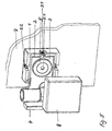
- a device shown in Figure 1 preferably consists of a hinge with mutually movable hinge tabs 3 and 4 for rotatably connecting door and / or wall elements 7, wherein in Figure 1, only one element 7 is shown in the form of a glass.
- the glass elements are used eg for door systems and shower cubicles or shower partitions, which are arranged rigidly or pivotally on adjacent wall or glass elements.
- an intermediate slide 2 is guided, which is provided with a collar screw 2.2, which engages with its collar in a groove provided in the base body 1 1.7.
- the hinge tab 3 is located on the base body 1 and the intermediate slide 2, the hinge tab 3 is located.
- the hinge flap 3 has a collar screw 3.1, which engages with its collar in a provided in the intermediate slide 2 groove 2.5, wherein the glass sheet 7 are fixed by turning the grooves held in the grooves 1.7 and 2.5 collar screws 2.2 and 3.1 in the vertical or horizontal direction.
- the hinge flap 3 is movable in the intermediate slide 2 and can also be designed as a fixed angle to the wall mounting.
- the main body 1 is connected to the door and / or wall elements 7 by screws.
- an intermediate layer 6 is disposed between the main body 1 and the glass element 7 and in the main body 1, the intermediate layer 6 and the door and / or wall element 7 are each two openings 1.2 and 6.1 provided for the two mounting screws 1.3.
- Figure 2 An adhesive connection is also possible.
- the main body 1 is made without the openings 1.2.
- An intermediate layer 6 is not required for an adhesive bond.
- the base body 1 is here box-shaped and the side walls are provided with recesses 1.5 for receiving the collar screws 2.2 and recesses 1.4 for receiving or introducing the hinge plate 3.
- the recesses 1.5 have a groove 1.7 for receiving the collar of the screws 2.2.
- the recesses 1.5 are provided at the upper and lower edge of the main body 1.
- the recess 1.6 is required so that the collar screw 3.1 is accessible after introducing intermediate slide 2 and hinge tabs 3 in the base body 1.
- the main body 1 is thereby universally applicable depending on the application position or stop side of the hinge.
- the main body 1 is preferably provided with grooves 1.8 for vertical guidance and receiving the intermediate slide 2.
- the base body 1 has a receptacle 1.1 for receiving the fastening screw 5.1 of the clamping plate 5, wherein the clamping disc 5 fixed immovably with the fastening screw 5.1 on the recording 1.1 the hinge plate 3 and the intermediate slide 2 in the base body 1.
- the intermediate slide 2 ( Figure 3) is located in the base body 1 and is guided by the guide 2.3 and the grooves 1.8 in the base body at a vertical adjustment.
- the intermediate slide 2 is provided with a recess 2.6 and guide walls 2.8 for receiving and guiding the hinge plate 3 and with a recess 2.4 with groove 2.5 for receiving the collar screw 3.1 of the hinge plate 3.
- the hinge flap 3 is shown in FIG. Between slide 2 and hinge tabs 3 each have a collar screw 2.2 or 3.1 with thread 2.7 or 3.2.
- the collar screw 2.2 is connected by the groove 1.7 with the base body 1 and moves by rotation in conjunction with the thread 2.7 the intermediate slide 2 in the vertical direction.
Landscapes
- Engineering & Computer Science (AREA)
- Mechanical Engineering (AREA)
- Hinges (AREA)
- Connection Of Plates (AREA)
- Securing Of Glass Panes Or The Like (AREA)
- Power-Operated Mechanisms For Wings (AREA)
Claims (13)
- Dispositif pour fixer et/ ou relier de manière rotative des éléments de porte et/ou des éléments de paroi, en particulier une porte vitrée, à ou éventuellement avec une partie de paroi, sur lesquels sont placées par assemblage mécanique et par adhérence une équerre avec des pentures ou une charnière avec des pentures mobiles les unes par rapport aux autres, et des moyens sont prévus pour un déplacement horizontal et vertical, caractérisé en ce qu'une coulisse intermédiaire (2) est guidée dans un corps de base (1) relié à l'élément de porte et/ou de paroi, ladite coulisse étant pourvue d'une vis d'assemblage (2.2) qui s'engage avec sa collerette dans une rainure (1.7) prévue dans le corps de base (1), reposant en outre sur le corps de base (1) et sur la coulisse intermédiaire (2) de la penture (3) qui présente une vis d'assemblage (3.1) qui s'engage avec sa collerette dans une rainure (2.5) prévue dans la coulisse intermédiaire (2), l'élément de porte et/ou de paroi (7) étant déplaçable en faisant tourner les vis d'assemblage (2.2 et 3.1) maintenues dans les rainures (1.7 et 2.5) dans le sens vertical ou horizontal.
- Dispositif selon la revendication 1, caractérisé en ce que le corps de base (1) est relié à l'élément de porte et/ ou de paroi (7) en le vissant ou en le collant.
- Dispositif selon l'une des revendications précédentes, caractérisé en ce que le corps de base (1) est relié à l'élément de porte et/ou de paroi (7) en le vissant, une couche intermédiaire (6) étant prévue entre le corps de base (1) et l'élément de porte et/ou de paroi (7), et des ouvertures (1.2, 6.1) étant prévues dans le corps de base (1), dans la couche intermédiaire (6) et dans l'élément de porte et/ ou de paroi (7) pour au moins une vis de fixation (1.3).
- Dispositif selon l'une des revendications précédentes, caractérisé en ce que le corps de base (1) est conçu de préférence en forme de boítier, les parois latérales étant pourvues de creux (1.5, 1.6) ou éventuellement d'évidements (1.4).
- Dispositif selon la revendication 4, caractérisé en ce que les creux (1.5) présentent une rainure (1.7).
- Dispositif selon la revendication 4, caractérisé en ce que l'évidement (1.4) sert à loger la penture (3).
- Dispositif selon l'une des revendications précédentes, caractérisé en ce que le corps de base (1) est pourvu de rainures (1.8) afin de guider et de loger la coulisse intermédiaire (2).
- Dispositif selon l'une des revendications précédentes, caractérisé en ce que le corps de base (1) présente un logement (1.1) afin de loger une vis de fixation (5.1) d'un disque de fixation (5).
- Dispositif selon l'une des revendications précédentes, caractérisé en ce que la coulisse intermédiaire (2) est pourvue d'un évidement (2.6) pour loger la penture (3), et d'un creux (2.4) avec une rainure (2.5) pour loger la vis d'assemblage (3.1), et en ce que des guidages (2.3) sont en outre prévus, qui servent à guider la coulisse intermédiaire (2) dans les rainures (1.8) du corps de base (1).
- Dispositif selon l'une des revendications précédentes, caractérisé en ce que la coulisse intermédiaire (2) présente une vis d'assemblage (2.2) avec un filetage (2.7).
- Dispositif selon l'une des revendications précédentes, caractérisé en ce que la penture (3) présente une vis d'assemblage (3.1) avec un filetage (3.2).
- Dispositif selon la revendication 8, caractérisé en ce que la vis de fixation (5.1) fixe le disque de serrage (5) sur le corps de base (1) par l'intermédiaire du logement (1.1), de la penture (3) et de la coulisse intermédiaire (2).
- Dispositif selon l'une des revendications précédentes, caractérisé en ce que le corps de base (1) est pourvu d'une coulisse intermédiaire (2) intercalée et d'une penture introduite (3) avec un couvercle (8).
Applications Claiming Priority (2)
| Application Number | Priority Date | Filing Date | Title |
|---|---|---|---|
| DE10310700 | 2003-03-10 | ||
| DE10310700A DE10310700B3 (de) | 2003-03-10 | 2003-03-10 | Vorrichtung zur Befestigung und/oder drehbeweglichen Verbindung von Tür- und/oder Wandelementen |
Publications (2)
| Publication Number | Publication Date |
|---|---|
| EP1457629A1 EP1457629A1 (fr) | 2004-09-15 |
| EP1457629B1 true EP1457629B1 (fr) | 2005-07-27 |
Family
ID=32087395
Family Applications (1)
| Application Number | Title | Priority Date | Filing Date |
|---|---|---|---|
| EP04090023A Expired - Lifetime EP1457629B1 (fr) | 2003-03-10 | 2004-01-23 | Dispositif pour la fixation et/ou la connexion rotative d' éléments de porte et/ou de paroi |
Country Status (5)
| Country | Link |
|---|---|
| EP (1) | EP1457629B1 (fr) |
| AT (1) | ATE300652T1 (fr) |
| DE (2) | DE10310700B3 (fr) |
| ES (1) | ES2246489T3 (fr) |
| PL (1) | PL202456B1 (fr) |
Families Citing this family (4)
| Publication number | Priority date | Publication date | Assignee | Title |
|---|---|---|---|---|
| US20110024590A1 (en) | 2009-07-28 | 2011-02-03 | Maax Bath Inc. | Hardware for Mounting Glass Panels or Similar Structures |
| DE202011101342U1 (de) * | 2011-05-25 | 2012-08-27 | Prämeta GmbH & Co. KG | Scharnier |
| CN105909101B (zh) * | 2016-06-17 | 2017-12-12 | 叶政 | 门调整机构 |
| CA3125121C (fr) * | 2020-07-20 | 2023-10-17 | Maax Bath Inc. | Assemblage de charniere de porte de douche |
Family Cites Families (5)
| Publication number | Priority date | Publication date | Assignee | Title |
|---|---|---|---|---|
| DE29516023U1 (de) * | 1995-10-10 | 1997-02-06 | Pauli + Sohn GmbH, 51545 Waldbröl | Beschlag |
| GB2311095B (en) * | 1996-03-15 | 1999-07-14 | Plus Plan | Hinge |
| DE19960723C2 (de) * | 1999-12-16 | 2002-07-18 | Dorma Gmbh & Co Kg | Justierbares Band |
| EP1201171B1 (fr) * | 2000-10-27 | 2008-08-13 | DORMA GmbH + Co. KG | Ferrure pour fixation et justage de feuilles de verre |
| DE10118223C2 (de) * | 2001-04-12 | 2003-04-30 | Hubert Hefel | Klemmbeschlag für Duschabtrennungen |
-
2003
- 2003-03-10 DE DE10310700A patent/DE10310700B3/de not_active Expired - Fee Related
-
2004
- 2004-01-23 EP EP04090023A patent/EP1457629B1/fr not_active Expired - Lifetime
- 2004-01-23 AT AT04090023T patent/ATE300652T1/de active
- 2004-01-23 DE DE502004000031T patent/DE502004000031D1/de not_active Expired - Lifetime
- 2004-01-23 ES ES04090023T patent/ES2246489T3/es not_active Expired - Lifetime
- 2004-02-23 PL PL365510A patent/PL202456B1/pl not_active IP Right Cessation
Also Published As
| Publication number | Publication date |
|---|---|
| PL202456B1 (pl) | 2009-06-30 |
| ES2246489T3 (es) | 2006-02-16 |
| DE502004000031D1 (de) | 2005-09-01 |
| EP1457629A1 (fr) | 2004-09-15 |
| ATE300652T1 (de) | 2005-08-15 |
| PL365510A1 (en) | 2004-09-20 |
| DE10310700B3 (de) | 2004-05-06 |
Similar Documents
| Publication | Publication Date | Title |
|---|---|---|
| EP2715021B1 (fr) | Scharnière | |
| DE19956756C2 (de) | Einstellbarer Mitnehmer für einen Fensterheber einer rahmenlosen Fahrzeugtür | |
| EP1108843B1 (fr) | Element en verre avec penture réglable | |
| EP2365167B1 (fr) | Bande de porte, notamment pour portes de fermeture de bâtiment | |
| EP0285229A2 (fr) | Charnière réglable, en particulier pour portes | |
| EP3103948B1 (fr) | Penture pour une porte ou une fenêtre | |
| EP1091067B1 (fr) | Charnière pour portes ou fenêtres | |
| EP1394347B1 (fr) | Dispositif de guidage pour partitions coulissantes et élément de guidage élastique | |
| EP0444405B1 (fr) | Ferrure pour portes ou fenêtres | |
| DE69805698T2 (de) | Verfahren zur Befestigung eines Türblattes an der Tür eines Einbauhaushaltgerätes | |
| DE19858709A1 (de) | Scharnier, insbesondere für Türflügel von Duschabtrennungen | |
| EP1764018B1 (fr) | Système pour la fixation d'une plaque | |
| DE10310700B3 (de) | Vorrichtung zur Befestigung und/oder drehbeweglichen Verbindung von Tür- und/oder Wandelementen | |
| EP1013210B1 (fr) | Cloison de douche | |
| WO2011006846A1 (fr) | Dispositif d'entraînement destiné à relier une vitre de fenêtre à un lève-vitre d'un véhicule automobile | |
| EP1718835A1 (fr) | Dispositif de fixation pour un rail de glissement ou de guidage | |
| DE10118223C2 (de) | Klemmbeschlag für Duschabtrennungen | |
| EP1243214B1 (fr) | Charnière et panneau de séparation, en particulier cabine de douche avec charnière pour permettre la rotation d'une porte en verre | |
| EP3029227B2 (fr) | Ferrure dotée d'une plage de serrage réglable | |
| DE102004043000A1 (de) | Fahrzeugtür | |
| DE102006012157B4 (de) | Dreidimensional-verstellbares Bandtaschensystem mit Verstellhilfe für die Höheneinstellung und zugehöriges Rahmenteil | |
| DE20219264U1 (de) | Vorrichtung zum Verbinden des Befestigungsbereichs einer Führungsschiene mit dem Türboden einer Fahrzeugtür | |
| EP1898033B1 (fr) | Ferrure | |
| DE202005010513U1 (de) | Schwenktür mit einer Halterung zur Einspannung einer Glasscheibe und eine Duschabtrennung mit einer solchen Schwenktür | |
| EP1439276B1 (fr) | Charnière |
Legal Events
| Date | Code | Title | Description |
|---|---|---|---|
| PUAI | Public reference made under article 153(3) epc to a published international application that has entered the european phase |
Free format text: ORIGINAL CODE: 0009012 |
|
| AK | Designated contracting states |
Kind code of ref document: A1 Designated state(s): AT BE BG CH CY CZ DE DK EE ES FI FR GB GR HU IE IT LI LU MC NL PT RO SE SI SK TR |
|
| AX | Request for extension of the european patent |
Extension state: AL LT LV MK |
|
| GRAP | Despatch of communication of intention to grant a patent |
Free format text: ORIGINAL CODE: EPIDOSNIGR1 |
|
| 17P | Request for examination filed |
Effective date: 20041207 |
|
| AKX | Designation fees paid |
Designated state(s): AT BE BG CH CY CZ DE DK EE ES FI FR GB GR HU IE IT LI LU MC NL PT RO SE SI SK TR |
|
| GRAS | Grant fee paid |
Free format text: ORIGINAL CODE: EPIDOSNIGR3 |
|
| GRAA | (expected) grant |
Free format text: ORIGINAL CODE: 0009210 |
|
| AK | Designated contracting states |
Kind code of ref document: B1 Designated state(s): AT BE BG CH CY CZ DE DK EE ES FI FR GB GR HU IE IT LI LU MC NL PT RO SE SI SK TR |
|
| PG25 | Lapsed in a contracting state [announced via postgrant information from national office to epo] |
Ref country code: SK Free format text: LAPSE BECAUSE OF FAILURE TO SUBMIT A TRANSLATION OF THE DESCRIPTION OR TO PAY THE FEE WITHIN THE PRESCRIBED TIME-LIMIT Effective date: 20050727 Ref country code: IE Free format text: LAPSE BECAUSE OF FAILURE TO SUBMIT A TRANSLATION OF THE DESCRIPTION OR TO PAY THE FEE WITHIN THE PRESCRIBED TIME-LIMIT Effective date: 20050727 Ref country code: TR Free format text: LAPSE BECAUSE OF FAILURE TO SUBMIT A TRANSLATION OF THE DESCRIPTION OR TO PAY THE FEE WITHIN THE PRESCRIBED TIME-LIMIT Effective date: 20050727 Ref country code: RO Free format text: LAPSE BECAUSE OF FAILURE TO SUBMIT A TRANSLATION OF THE DESCRIPTION OR TO PAY THE FEE WITHIN THE PRESCRIBED TIME-LIMIT Effective date: 20050727 Ref country code: FI Free format text: LAPSE BECAUSE OF FAILURE TO SUBMIT A TRANSLATION OF THE DESCRIPTION OR TO PAY THE FEE WITHIN THE PRESCRIBED TIME-LIMIT Effective date: 20050727 Ref country code: SI Free format text: LAPSE BECAUSE OF FAILURE TO SUBMIT A TRANSLATION OF THE DESCRIPTION OR TO PAY THE FEE WITHIN THE PRESCRIBED TIME-LIMIT Effective date: 20050727 Ref country code: EE Free format text: LAPSE BECAUSE OF FAILURE TO SUBMIT A TRANSLATION OF THE DESCRIPTION OR TO PAY THE FEE WITHIN THE PRESCRIBED TIME-LIMIT Effective date: 20050727 |
|
| REG | Reference to a national code |
Ref country code: GB Ref legal event code: FG4D Free format text: NOT ENGLISH |
|
| REG | Reference to a national code |
Ref country code: CH Ref legal event code: EP |
|
| REG | Reference to a national code |
Ref country code: IE Ref legal event code: FG4D Free format text: LANGUAGE OF EP DOCUMENT: GERMAN |
|
| REF | Corresponds to: |
Ref document number: 502004000031 Country of ref document: DE Date of ref document: 20050901 Kind code of ref document: P |
|
| PG25 | Lapsed in a contracting state [announced via postgrant information from national office to epo] |
Ref country code: GR Free format text: LAPSE BECAUSE OF FAILURE TO SUBMIT A TRANSLATION OF THE DESCRIPTION OR TO PAY THE FEE WITHIN THE PRESCRIBED TIME-LIMIT Effective date: 20051027 Ref country code: SE Free format text: LAPSE BECAUSE OF FAILURE TO SUBMIT A TRANSLATION OF THE DESCRIPTION OR TO PAY THE FEE WITHIN THE PRESCRIBED TIME-LIMIT Effective date: 20051027 Ref country code: BG Free format text: LAPSE BECAUSE OF FAILURE TO SUBMIT A TRANSLATION OF THE DESCRIPTION OR TO PAY THE FEE WITHIN THE PRESCRIBED TIME-LIMIT Effective date: 20051027 Ref country code: DK Free format text: LAPSE BECAUSE OF FAILURE TO SUBMIT A TRANSLATION OF THE DESCRIPTION OR TO PAY THE FEE WITHIN THE PRESCRIBED TIME-LIMIT Effective date: 20051027 |
|
| GBT | Gb: translation of ep patent filed (gb section 77(6)(a)/1977) |
Effective date: 20051024 |
|
| PG25 | Lapsed in a contracting state [announced via postgrant information from national office to epo] |
Ref country code: PT Free format text: LAPSE BECAUSE OF FAILURE TO SUBMIT A TRANSLATION OF THE DESCRIPTION OR TO PAY THE FEE WITHIN THE PRESCRIBED TIME-LIMIT Effective date: 20051227 |
|
| PG25 | Lapsed in a contracting state [announced via postgrant information from national office to epo] |
Ref country code: HU Free format text: LAPSE BECAUSE OF FAILURE TO SUBMIT A TRANSLATION OF THE DESCRIPTION OR TO PAY THE FEE WITHIN THE PRESCRIBED TIME-LIMIT Effective date: 20060128 |
|
| PG25 | Lapsed in a contracting state [announced via postgrant information from national office to epo] |
Ref country code: MC Free format text: LAPSE BECAUSE OF NON-PAYMENT OF DUE FEES Effective date: 20060131 Ref country code: LU Free format text: LAPSE BECAUSE OF NON-PAYMENT OF DUE FEES Effective date: 20060131 |
|
| REG | Reference to a national code |
Ref country code: ES Ref legal event code: FG2A Ref document number: 2246489 Country of ref document: ES Kind code of ref document: T3 |
|
| REG | Reference to a national code |
Ref country code: IE Ref legal event code: FD4D |
|
| ET | Fr: translation filed | ||
| PLBE | No opposition filed within time limit |
Free format text: ORIGINAL CODE: 0009261 |
|
| STAA | Information on the status of an ep patent application or granted ep patent |
Free format text: STATUS: NO OPPOSITION FILED WITHIN TIME LIMIT |
|
| 26N | No opposition filed |
Effective date: 20060428 |
|
| PGFP | Annual fee paid to national office [announced via postgrant information from national office to epo] |
Ref country code: TR Payment date: 20061224 Year of fee payment: 4 |
|
| PGFP | Annual fee paid to national office [announced via postgrant information from national office to epo] |
Ref country code: ES Payment date: 20080130 Year of fee payment: 5 |
|
| PG25 | Lapsed in a contracting state [announced via postgrant information from national office to epo] |
Ref country code: CY Free format text: LAPSE BECAUSE OF FAILURE TO SUBMIT A TRANSLATION OF THE DESCRIPTION OR TO PAY THE FEE WITHIN THE PRESCRIBED TIME-LIMIT Effective date: 20050727 |
|
| PGFP | Annual fee paid to national office [announced via postgrant information from national office to epo] |
Ref country code: IT Payment date: 20090127 Year of fee payment: 6 |
|
| REG | Reference to a national code |
Ref country code: ES Ref legal event code: FD2A Effective date: 20090124 |
|
| PG25 | Lapsed in a contracting state [announced via postgrant information from national office to epo] |
Ref country code: ES Free format text: LAPSE BECAUSE OF NON-PAYMENT OF DUE FEES Effective date: 20090124 |
|
| PG25 | Lapsed in a contracting state [announced via postgrant information from national office to epo] |
Ref country code: IT Free format text: LAPSE BECAUSE OF NON-PAYMENT OF DUE FEES Effective date: 20100123 |
|
| PG25 | Lapsed in a contracting state [announced via postgrant information from national office to epo] |
Ref country code: TR Free format text: LAPSE BECAUSE OF FAILURE TO SUBMIT A TRANSLATION OF THE DESCRIPTION OR TO PAY THE FEE WITHIN THE PRESCRIBED TIME-LIMIT Effective date: 20100123 |
|
| PGFP | Annual fee paid to national office [announced via postgrant information from national office to epo] |
Ref country code: NL Payment date: 20140121 Year of fee payment: 11 Ref country code: CZ Payment date: 20140117 Year of fee payment: 11 Ref country code: BE Payment date: 20140121 Year of fee payment: 11 Ref country code: CH Payment date: 20140121 Year of fee payment: 11 |
|
| PGFP | Annual fee paid to national office [announced via postgrant information from national office to epo] |
Ref country code: AT Payment date: 20140113 Year of fee payment: 11 Ref country code: FR Payment date: 20140123 Year of fee payment: 11 |
|
| PGFP | Annual fee paid to national office [announced via postgrant information from national office to epo] |
Ref country code: GB Payment date: 20140121 Year of fee payment: 11 |
|
| PG25 | Lapsed in a contracting state [announced via postgrant information from national office to epo] |
Ref country code: BE Free format text: LAPSE BECAUSE OF NON-PAYMENT OF DUE FEES Effective date: 20150131 |
|
| REG | Reference to a national code |
Ref country code: NL Ref legal event code: V1 Effective date: 20150801 |
|
| REG | Reference to a national code |
Ref country code: CH Ref legal event code: PL |
|
| REG | Reference to a national code |
Ref country code: AT Ref legal event code: MM01 Ref document number: 300652 Country of ref document: AT Kind code of ref document: T Effective date: 20150123 |
|
| GBPC | Gb: european patent ceased through non-payment of renewal fee |
Effective date: 20150123 |
|
| PG25 | Lapsed in a contracting state [announced via postgrant information from national office to epo] |
Ref country code: NL Free format text: LAPSE BECAUSE OF NON-PAYMENT OF DUE FEES Effective date: 20150801 |
|
| PG25 | Lapsed in a contracting state [announced via postgrant information from national office to epo] |
Ref country code: CZ Free format text: LAPSE BECAUSE OF NON-PAYMENT OF DUE FEES Effective date: 20150123 Ref country code: LI Free format text: LAPSE BECAUSE OF NON-PAYMENT OF DUE FEES Effective date: 20150131 Ref country code: CH Free format text: LAPSE BECAUSE OF NON-PAYMENT OF DUE FEES Effective date: 20150131 Ref country code: GB Free format text: LAPSE BECAUSE OF NON-PAYMENT OF DUE FEES Effective date: 20150123 |
|
| REG | Reference to a national code |
Ref country code: FR Ref legal event code: ST Effective date: 20150930 |
|
| PG25 | Lapsed in a contracting state [announced via postgrant information from national office to epo] |
Ref country code: AT Free format text: LAPSE BECAUSE OF NON-PAYMENT OF DUE FEES Effective date: 20150123 Ref country code: FR Free format text: LAPSE BECAUSE OF NON-PAYMENT OF DUE FEES Effective date: 20150202 |
|
| PGFP | Annual fee paid to national office [announced via postgrant information from national office to epo] |
Ref country code: DE Payment date: 20160126 Year of fee payment: 13 |
|
| REG | Reference to a national code |
Ref country code: DE Ref legal event code: R119 Ref document number: 502004000031 Country of ref document: DE |
|
| PG25 | Lapsed in a contracting state [announced via postgrant information from national office to epo] |
Ref country code: DE Free format text: LAPSE BECAUSE OF NON-PAYMENT OF DUE FEES Effective date: 20170801 |