EP1457721A1 - Unité d'étranglement pour moteurs à combustion interne - Google Patents
Unité d'étranglement pour moteurs à combustion interne Download PDFInfo
- Publication number
- EP1457721A1 EP1457721A1 EP04100985A EP04100985A EP1457721A1 EP 1457721 A1 EP1457721 A1 EP 1457721A1 EP 04100985 A EP04100985 A EP 04100985A EP 04100985 A EP04100985 A EP 04100985A EP 1457721 A1 EP1457721 A1 EP 1457721A1
- Authority
- EP
- European Patent Office
- Prior art keywords
- throttle
- unit
- sector gear
- shaft
- blow
- Prior art date
- Legal status (The legal status is an assumption and is not a legal conclusion. Google has not performed a legal analysis and makes no representation as to the accuracy of the status listed.)
- Withdrawn
Links
- 238000002485 combustion reaction Methods 0.000 title claims abstract description 6
- 230000007246 mechanism Effects 0.000 claims abstract description 18
- 230000005540 biological transmission Effects 0.000 claims abstract description 15
- 230000009467 reduction Effects 0.000 claims abstract description 8
- 230000009347 mechanical transmission Effects 0.000 claims abstract description 4
- 230000009471 action Effects 0.000 claims description 2
- 238000010586 diagram Methods 0.000 description 3
- 238000005516 engineering process Methods 0.000 description 2
- 230000007704 transition Effects 0.000 description 2
- 230000001133 acceleration Effects 0.000 description 1
- 230000009118 appropriate response Effects 0.000 description 1
- 230000008859 change Effects 0.000 description 1
- 238000006243 chemical reaction Methods 0.000 description 1
- 238000013016 damping Methods 0.000 description 1
- 238000006073 displacement reaction Methods 0.000 description 1
- 239000003344 environmental pollutant Substances 0.000 description 1
- 238000012423 maintenance Methods 0.000 description 1
- 238000004519 manufacturing process Methods 0.000 description 1
- 239000000203 mixture Substances 0.000 description 1
- 230000010355 oscillation Effects 0.000 description 1
- 231100000719 pollutant Toxicity 0.000 description 1
- 230000036316 preload Effects 0.000 description 1
- 230000000284 resting effect Effects 0.000 description 1
- 230000035945 sensitivity Effects 0.000 description 1
- 238000004148 unit process Methods 0.000 description 1
Images



Classifications
-
- F—MECHANICAL ENGINEERING; LIGHTING; HEATING; WEAPONS; BLASTING
- F02—COMBUSTION ENGINES; HOT-GAS OR COMBUSTION-PRODUCT ENGINE PLANTS
- F02D—CONTROLLING COMBUSTION ENGINES
- F02D9/00—Controlling engines by throttling air or fuel-and-air induction conduits or exhaust conduits
- F02D9/08—Throttle valves specially adapted therefor; Arrangements of such valves in conduits
- F02D9/10—Throttle valves specially adapted therefor; Arrangements of such valves in conduits having pivotally-mounted flaps
- F02D9/1065—Mechanical control linkage between an actuator and the flap, e.g. including levers, gears, springs, clutches, limit stops of the like
-
- F—MECHANICAL ENGINEERING; LIGHTING; HEATING; WEAPONS; BLASTING
- F02—COMBUSTION ENGINES; HOT-GAS OR COMBUSTION-PRODUCT ENGINE PLANTS
- F02D—CONTROLLING COMBUSTION ENGINES
- F02D11/00—Arrangements for, or adaptations to, non-automatic engine control initiation means, e.g. operator initiated
- F02D11/06—Arrangements for, or adaptations to, non-automatic engine control initiation means, e.g. operator initiated characterised by non-mechanical control linkages, e.g. fluid control linkages or by control linkages with power drive or assistance
- F02D11/10—Arrangements for, or adaptations to, non-automatic engine control initiation means, e.g. operator initiated characterised by non-mechanical control linkages, e.g. fluid control linkages or by control linkages with power drive or assistance of the electric type
- F02D11/105—Arrangements for, or adaptations to, non-automatic engine control initiation means, e.g. operator initiated characterised by non-mechanical control linkages, e.g. fluid control linkages or by control linkages with power drive or assistance of the electric type characterised by the function converting demand to actuation, e.g. a map indicating relations between an accelerator pedal position and throttle valve opening or target engine torque
-
- F—MECHANICAL ENGINEERING; LIGHTING; HEATING; WEAPONS; BLASTING
- F02—COMBUSTION ENGINES; HOT-GAS OR COMBUSTION-PRODUCT ENGINE PLANTS
- F02D—CONTROLLING COMBUSTION ENGINES
- F02D11/00—Arrangements for, or adaptations to, non-automatic engine control initiation means, e.g. operator initiated
- F02D11/06—Arrangements for, or adaptations to, non-automatic engine control initiation means, e.g. operator initiated characterised by non-mechanical control linkages, e.g. fluid control linkages or by control linkages with power drive or assistance
- F02D11/10—Arrangements for, or adaptations to, non-automatic engine control initiation means, e.g. operator initiated characterised by non-mechanical control linkages, e.g. fluid control linkages or by control linkages with power drive or assistance of the electric type
- F02D11/107—Safety-related aspects
-
- F—MECHANICAL ENGINEERING; LIGHTING; HEATING; WEAPONS; BLASTING
- F16—ENGINEERING ELEMENTS AND UNITS; GENERAL MEASURES FOR PRODUCING AND MAINTAINING EFFECTIVE FUNCTIONING OF MACHINES OR INSTALLATIONS; THERMAL INSULATION IN GENERAL
- F16K—VALVES; TAPS; COCKS; ACTUATING-FLOATS; DEVICES FOR VENTING OR AERATING
- F16K31/00—Actuating devices; Operating means; Releasing devices
- F16K31/02—Actuating devices; Operating means; Releasing devices electric; magnetic
- F16K31/04—Actuating devices; Operating means; Releasing devices electric; magnetic using a motor
- F16K31/041—Actuating devices; Operating means; Releasing devices electric; magnetic using a motor for rotating valves
- F16K31/043—Actuating devices; Operating means; Releasing devices electric; magnetic using a motor for rotating valves characterised by mechanical means between the motor and the valve, e.g. lost motion means reducing backlash, clutches, brakes or return means
-
- F—MECHANICAL ENGINEERING; LIGHTING; HEATING; WEAPONS; BLASTING
- F02—COMBUSTION ENGINES; HOT-GAS OR COMBUSTION-PRODUCT ENGINE PLANTS
- F02D—CONTROLLING COMBUSTION ENGINES
- F02D9/00—Controlling engines by throttling air or fuel-and-air induction conduits or exhaust conduits
- F02D9/02—Controlling engines by throttling air or fuel-and-air induction conduits or exhaust conduits concerning induction conduits
- F02D2009/0201—Arrangements; Control features; Details thereof
- F02D2009/0269—Throttle closing springs; Acting of throttle closing springs on the throttle shaft
-
- F—MECHANICAL ENGINEERING; LIGHTING; HEATING; WEAPONS; BLASTING
- F02—COMBUSTION ENGINES; HOT-GAS OR COMBUSTION-PRODUCT ENGINE PLANTS
- F02D—CONTROLLING COMBUSTION ENGINES
- F02D9/00—Controlling engines by throttling air or fuel-and-air induction conduits or exhaust conduits
- F02D9/02—Controlling engines by throttling air or fuel-and-air induction conduits or exhaust conduits concerning induction conduits
- F02D2009/0201—Arrangements; Control features; Details thereof
- F02D2009/0277—Fail-safe mechanisms, e.g. with limp-home feature, to close throttle if actuator fails, or if control cable sticks or breaks
Definitions
- the present invention relates to a throttle unit for internal combustion engines, especially for vehicles, of the type controlled by an electric motor and comprising a "limp home" device.
- the system mechanically and automatically positions the throttle in an accelerated slow running condition just sufficient to keep the vehicle moving.
- an electric motor 1 operates, by means of a suitable reduction unit (generally comprising a sprocket gear 2 and a sector gear 3), the throttle shaft 4, against the bias offered by a pair of pre-loaded springs 5 and 6.
- spring 5 operates in the angle range of the throttle, which extends from the emergency position LH to that of full WOT, while the spring 6 operates in the remaining portion of the run, from the blow-by position TR to the emergency or "limp home" position LH, in which a suitable stopping system (not shown)is provided to neutralise it.
- Throttle units are also known, for example from DE-A1-4039937 and from USA-6089208, which use, to control the throttle valve, pivoting arm systems directly operated by an electric motor, against the bias of a spring. Both these devices, however, do not exploit a sprocket and sector gear reduction unit to reduce the revolutions of the operating motor, which causes noticeable disadvantages from a manufacturing and functional point of view (requiring the use of more powerful and hence bulkier motors, which are further badly exploited due to the low number of revolutions during normal working conditions).
- the choice of the transmission ratio between motor and throttle shaft is a compromise between a good modular capability near the slow running condition (where, small angle variations of the throttle correspond to large flow variations of the supplied mixture) and the requirement of a high operation speed near the maximum condition (where large angle variations of the throttle correspond to small flow variations).
- a throttle unit for internal combustion engines of the type comprising a throttle capable of taking up a blow-by position, a position corresponding to the normal engine idling condition, a fully-open position, a plurality of intermediate positions between the previous ones and a "limp home" position and in which the throttle shaft is controlled by an electric motor through a mechanical transmission comprising a sprocket and sector gear reduction unit, characterised in that the transmission from the sector gear to the throttle shaft consists of an articulated quadrilateral kinematic mechanism, the dead-centre condition of which corresponds to the throttle blow-by position, and in that a single spring is provided which opposes the rotations imparted by the motor to the sector gear in order to draw the throttle towards the fully-open position.
- the articulated quadrilateral kinematic mechanism comprises: a connecting rod with one end having its fulcrum on the sector gear, said fulcrum and a crank which connects the throttle shaft to the other end of the connecting rod.
- the rotation centres of the sector gear and of the ends of the connecting rod are aligned in the dead-point condition corresponding to the throttle blow-by position.
- a second spring can be provided, keyed for example on the throttle shaft, which operates in an opposite direction to said return spring, but imparting a noticeably smaller action than the same.
- the invention provides an electronic control system of the electric motor, comprising, in a known manner, a position computing unit and a power unit, the control programme of said system being processed according to an algorithm which takes into account the variableness of the transmission ratio between the electric motor and the throttle, produced by said articulated quadrilateral kinematic mechanism.
- the programme controlling said electronic system provides that, during normal functioning, the throttle can never exceed the blow-by position. Thus, during normal conditions, the throttle cannot move into the "limp-home" position rotating in the direction it does instead when failure occurs.
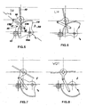
- the device of the present invention has a transmission of the drive from the electric motor 10 to the shaft 11 of the throttle 12 which comprises a suitable reduction unit with sprocket 13 and sector gear 14 and an articulated quadrilateral kinematic mechanism 15 consisting of a fulcrum 16 on the sector gear 14, of a small connecting rod 17 and of a crank 18 which acts on the shaft 11 of the throttle 12. It is further provided a return spring 19 acting on the shaft 14A of the sector gear.
- the "limp home" position of the throttle 12 is automatically reached, in the case of failure of the motor 10, by exploiting the property of inversion of the motion of the shaft 11 of the throttle 12 beyond the dead-centre of the articulated quadrilateral kinematic mechanism 15 of the device itself.
- the mechanism is assembled so that, in correspondence of the TR position of the throttle 12, the centre of rotation 14A of the sector gear 14 is aligned - discontinuous line L - with the rotation centres of end 17A (coinciding with the fulcrum 16) and 17B (pivoted to the crank 18), respectively, of the connecting rod 17.
- the range of normal working conditions of the throttle unit is that ranging from the position of fig. 5, through the position of fig. 7 to the position of maximum opening WOT of fig. 8 and viceversa, with anti-clockwise and clockwise rotations, respectively, of the sector gear 14 controlled to open (acceleration) and to close (deceleration) by the motor 10 controlled, through a potentiometer (see further on), by the vehicle accelerator.
- the "limp home" position is determined by an end stop, identified by the reference number 20, and is hence inherently accurate. Furthermore, within the normal functioning range there is a complete lack of impacts and of vibrations which may occur with conventional devices, caused by the load discontinuities which were produced by the passages from the control with one to that with the other of the two springs of such devices.
- fig. 9 are illustrated the angular positions of the throttle 12 as a function of the angular displacements of the sector gear 14 of the transmission between the electric motor 10 and the shaft 11 of the same throttle 12 (continuous line) as well as the transmission ratio between the shaft 11 of the throttle 12 and the shaft 14A of the sector gear 14 (dotted line).
- a system which consists of a position computing unit UCP and of a power unit DP for the motion of the motor 10, and which is associated to the vehicle electric control unit CE.
- the UCP unit processes the external position signal PE, determined by the position of the accelerator, the inner signal of the throttle position PI and the power driver DP for the operation of the motor 10, as illustrated in fig. 10 of the attached drawings.
- the UCP unit - through the control of the motor always in the same direction - brings the throttle from the "limp home" position LH (in which it finds itself with the motor switched off), inclined by about 12° to the zero plane, to the blow-by position TR, inclined by about 6°, corresponding to the lowest potentiometer voltage and it then causes it to increase up to the position of full WOT, inclined by about 92°, to which corresponds, in the control system, a voltage set in the programme; it then brings back the throttle 12, reversing the direction of rotation of the motor 10, to an engine idling position (between that of "limp home” LH and that of blow-by TR) to which corresponds in the potentiometer a voltage set in the programme according to external parameters, such as room temperature, engine temperature, and any auxiliary loads on the engine possibly present.
- the initial increase allows to update to the current conditions the motion law produced by the electric motor 10, to then have the throttle 12 reach the positions required by the driver through the accelerator control.
- any variation of the external position signal PE informs the UCP unit that it must cause the throttle 12 to reach a new position, which is calculated taking into account all the variables which concur to its correct determination, in form of the modulus and sign difference of the two signals PI-PE.
- the sign is used to determine the direction of rotation of the motor 10, the modulus is used to establish the position correction ratio, and the approach damping (ramp) is chosen to guarantee the absence of oscillations of the throttle 12 about the desired position.
- the control system also provides means to inform the UCP unit of an approach to the blow-by position TR - inclination of the throttle by about 6° to the zero plane - the exceeding of which would mean entering the forbidden position range in normal working conditions; the information "TR position reached” activates a control loop of the electronic circuit for the maintenance of said position. PE values below those corresponding to the blow-by position TR (6° to the zero plane) or above those corresponding to the full WOT position (92° to the zero plane) are not accepted, to avoid throttle impacts due to reached mechanical limit.
Landscapes
- Engineering & Computer Science (AREA)
- General Engineering & Computer Science (AREA)
- Mechanical Engineering (AREA)
- Chemical & Material Sciences (AREA)
- Combustion & Propulsion (AREA)
- Control Of Throttle Valves Provided In The Intake System Or In The Exhaust System (AREA)
Applications Claiming Priority (2)
| Application Number | Priority Date | Filing Date | Title |
|---|---|---|---|
| ITMI20030482 | 2003-03-13 | ||
| ITMI20030482 ITMI20030482A1 (it) | 2003-03-13 | 2003-03-13 | Corpo farfallato per motori a combustione interna. |
Publications (1)
| Publication Number | Publication Date |
|---|---|
| EP1457721A1 true EP1457721A1 (fr) | 2004-09-15 |
Family
ID=32750505
Family Applications (1)
| Application Number | Title | Priority Date | Filing Date |
|---|---|---|---|
| EP04100985A Withdrawn EP1457721A1 (fr) | 2003-03-13 | 2004-03-10 | Unité d'étranglement pour moteurs à combustion interne |
Country Status (2)
| Country | Link |
|---|---|
| EP (1) | EP1457721A1 (fr) |
| IT (1) | ITMI20030482A1 (fr) |
Cited By (3)
| Publication number | Priority date | Publication date | Assignee | Title |
|---|---|---|---|---|
| WO2010115624A1 (fr) * | 2009-04-08 | 2010-10-14 | Axel Ahnert | Ensemble soupape |
| CN101725753B (zh) * | 2009-12-21 | 2011-12-07 | 阮迪荣 | 一种可脱位复位的电控阀齿轮传动机构 |
| CN112377313A (zh) * | 2020-11-09 | 2021-02-19 | 一汽解放汽车有限公司 | 一种电控排气管理阀及车辆 |
Families Citing this family (1)
| Publication number | Priority date | Publication date | Assignee | Title |
|---|---|---|---|---|
| CN110206649B (zh) * | 2019-06-30 | 2023-11-24 | 湖北汽车工业学院 | 一种光圈式电子节气门装置 |
Citations (4)
| Publication number | Priority date | Publication date | Assignee | Title |
|---|---|---|---|---|
| US5113822A (en) * | 1989-08-29 | 1992-05-19 | Mitsubishi Denki K.K. | Throttle valve control apparatus for an internal combustion engine |
| DE4039937A1 (de) | 1990-12-14 | 1992-06-17 | Audi Ag | Leerlauffuellungsregler |
| EP0828067A2 (fr) * | 1996-09-03 | 1998-03-11 | Hitachi, Ltd. | Dispositif de commande de papillon pour moteur à combustion interne |
| US6089208A (en) | 1997-09-19 | 2000-07-18 | Hitachi, Ltd. | Throttle valve opening and closing apparatus for a vehicle, and vehicle internal combustion engine using the apparatus |
-
2003
- 2003-03-13 IT ITMI20030482 patent/ITMI20030482A1/it unknown
-
2004
- 2004-03-10 EP EP04100985A patent/EP1457721A1/fr not_active Withdrawn
Patent Citations (4)
| Publication number | Priority date | Publication date | Assignee | Title |
|---|---|---|---|---|
| US5113822A (en) * | 1989-08-29 | 1992-05-19 | Mitsubishi Denki K.K. | Throttle valve control apparatus for an internal combustion engine |
| DE4039937A1 (de) | 1990-12-14 | 1992-06-17 | Audi Ag | Leerlauffuellungsregler |
| EP0828067A2 (fr) * | 1996-09-03 | 1998-03-11 | Hitachi, Ltd. | Dispositif de commande de papillon pour moteur à combustion interne |
| US6089208A (en) | 1997-09-19 | 2000-07-18 | Hitachi, Ltd. | Throttle valve opening and closing apparatus for a vehicle, and vehicle internal combustion engine using the apparatus |
Cited By (3)
| Publication number | Priority date | Publication date | Assignee | Title |
|---|---|---|---|---|
| WO2010115624A1 (fr) * | 2009-04-08 | 2010-10-14 | Axel Ahnert | Ensemble soupape |
| CN101725753B (zh) * | 2009-12-21 | 2011-12-07 | 阮迪荣 | 一种可脱位复位的电控阀齿轮传动机构 |
| CN112377313A (zh) * | 2020-11-09 | 2021-02-19 | 一汽解放汽车有限公司 | 一种电控排气管理阀及车辆 |
Also Published As
| Publication number | Publication date |
|---|---|
| ITMI20030482A1 (it) | 2004-09-14 |
Similar Documents
| Publication | Publication Date | Title |
|---|---|---|
| US5014666A (en) | Load adjustment device | |
| US5775292A (en) | Load adjustment device | |
| US5131364A (en) | Throttle-valve connection | |
| KR101234651B1 (ko) | 연속 가변 밸브 리프트 장치 | |
| EP0523072A1 (fr) | Vanne-papillon. | |
| KR910009726B1 (ko) | 엔진의 드로틀밸브(throttle valve) 제어장치 | |
| US4548176A (en) | Rotating mechanism of throttle valve for fuel supply device of internal combustion engine | |
| EP1457721A1 (fr) | Unité d'étranglement pour moteurs à combustion interne | |
| JPH0568625B2 (fr) | ||
| JP4380072B2 (ja) | Egr弁一体型電子ベンチュリ | |
| JP3363176B2 (ja) | 駆動機械のための負荷調節装置 | |
| JPH1162643A5 (fr) | ||
| KR100473211B1 (ko) | 부하조절장치 | |
| US6089208A (en) | Throttle valve opening and closing apparatus for a vehicle, and vehicle internal combustion engine using the apparatus | |
| KR101903895B1 (ko) | 흡기매니폴드의 가변밸브 구동장치 | |
| JPH07180515A (ja) | 内燃機関の動弁装置 | |
| US5193503A (en) | Load adjustment device | |
| EP3832114B1 (fr) | Dispositif de papillon | |
| CN224064438U (zh) | 一种电子节气门体总成 | |
| JP2000297660A (ja) | ディーゼルエンジン用吸気流量制御装置 | |
| US5718201A (en) | Load adjustment device | |
| KR100194781B1 (ko) | 디젤엔진의 흡,배기와 연료분사 시기 조정장치 | |
| WO2018224020A1 (fr) | Procédé et système de commande pour mécanisme de levée de soupape variable en continu, et véhicule | |
| JP2001082179A (ja) | スロットル装置 | |
| JPH1018865A (ja) | スロットル弁制御装置 |
Legal Events
| Date | Code | Title | Description |
|---|---|---|---|
| PUAI | Public reference made under article 153(3) epc to a published international application that has entered the european phase |
Free format text: ORIGINAL CODE: 0009012 |
|
| AK | Designated contracting states |
Kind code of ref document: A1 Designated state(s): AT BE BG CH CY CZ DE DK EE ES FI FR GB GR HU IE IT LI LU MC NL PL PT RO SE SI SK TR |
|
| AX | Request for extension of the european patent |
Extension state: AL LT LV MK |
|
| AKX | Designation fees paid | ||
| REG | Reference to a national code |
Ref country code: DE Ref legal event code: 8566 |
|
| STAA | Information on the status of an ep patent application or granted ep patent |
Free format text: STATUS: THE APPLICATION IS DEEMED TO BE WITHDRAWN |
|
| 18D | Application deemed to be withdrawn |
Effective date: 20050316 |